Table of Contents
Advertisement
Advertisement
Table of Contents

Summary of Contents for BICOLD WBA Series
- Page 1 Air-cooled Water chillers WBA and Heat Pump WHA GENERAL TABLE OF CONTENTS 1. CE model plate Page Safety notes Page 1. Symbols on the unit Page 2. User Manual Page BICOLD Srl - Arzergrande (PD) - ITALY WBA CHILLER ________ USER MANUAL Release 110613...
- Page 2 For more information, consult the BICOLD Srl Engineering Department. (9) BICOLD Srl provides one year of warranty from the date of shipment and the warranty will be held valid only if no repairs or modifications of the unit have been carried out by personnel not authorised by BICOLD Srl.
- Page 3 3. SY SYMBOLS ON THE UNIT BODY GRAFIC FUNZIONE SYMBO FUNCTION SYMBO FUNKTION SÍMBOL FUNCIÓN DESSI FONCTION Ingresso cavo elettrico Electric cable inlet Eingang Stromkabel Entrada cable eléctrico Entrée câble électrique PERICOLO, PRESTARE ATTENZI ZIONE! DANGER, PAY ATTENTION! GEFAHR, VORSICHT! ¡PELIGRO, PRESTAR ATENCIÓ...
-
Page 4: Table Of Contents
The indication Environmental Protection supplies instructions for use of the machine. 4. USER INSTRUCTION MANUAL CONTENTS OF THE MANUAL 1. Introduction to the BICOLD WBA range ............05 1-1 Description of BICOLD WBA units ............05 1-2 Identification of the units ..............07 1-3 Operating conditions and limits ............ -
Page 5: Introduction To The Bicold Wba Range
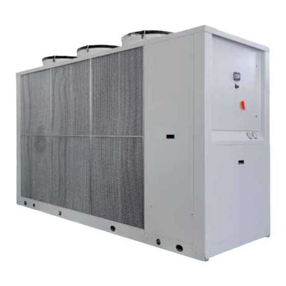
Introduction to the BICOLD WBA range 1.1 Description of the units The WBA series constitutes a range of air-cooled water chillers designed to meet the requirements of low and medium capacity air conditioning plants, operating with R410A, a non-flammable and non-toxic high efficiency refrigerant for optimal energy saving in operation of the unit. - Page 7 • remote keypad kit. Microprocessor controller All WBA series units are equipped with a microprocessor controller capable of managing the following functions: -water temperature control in the traditional method with a probe on the system return line (especially suitable for applications in which an inertia storage tank is installed);...
-
Page 8: Identification Of The Units
1.2 Identification of the units in the range BICOLD WBA WATER CHILLERS 1 - MODEL WB – Water chiller units with hermetic scroll compressors and plate evaporators. WH – Heat pump version 2 - CONDENSATION A = AIR-cooling with axial fans (suitable for outdoor installation);... -
Page 9: Operating Conditions And Limits
To avoid pump damage in the event of glycol percentages above 25%, consult the BICOLD Srl sales department. -
Page 10: Unit Performance
WARNING! WITHOUT GLYCOL IN THE SYSTEM: IMPORTANT! If the unit is not used in the winter the water in the circuit may freeze IMPORTANT! The use of mixtures of water with glycol affects performance characteristics of the unit 1-4 Unit performance 1.4.1 Cooling duty and electrical power consumption values Performance values of the models in the WBA range of chillers are shown below referred to water inlet/outlet temperature of 12/7 °... - Page 11 1.4.2 Sound pressure level The following table gives the noise data in Sound Pressure Lp(A) at 10 metres from the condensing coil and 1 metre height above ground in free field conditions (direction factor Q=2). The Sound Pressure level refers to the machine std layout with the compressors compartment insulated with sound absorbing matting.
-
Page 12: Installation Requirements
2 – INSTALLATION REQUIREMENTS 2.1 Lifting and transport... - Page 13 Before lifting the unit refer to the following WEIGHTS table, wherein values are calculated without the hydronic unit: Models WBA-1020 WBA-1026 WBA-1030 WBA-1034 WBA-1039 WBA-1045 Weight Models WBA-1053 WBA-1059 WBA-1066 WBA-1075 WBA-1090 WBA-1098 WBA-1110 Weight 1020 Models WBA-1126 WBA-1145 WBA-1158 WBA-2180 WBA-2195 WBA-2200...
-
Page 14: Installation And Positioning
DANGER! The unit must be handled with care to avoid damage to the external structure and the internal mechanical end electrical components. Also make sure that there are no obstacles or persons along the route, to avoid the risk of collision, crushing or overturning of the lifting and handling vehicle. - Page 15 The area above the unit must be completely free of obstacles in such a way as to guarantee unimpeded air flow from the condensing fans. If the unit is surrounded by walls, the minimum clearances shown are still valid as long as at least the two adjoining walls closest to the unit are no higher than the total height of the unit.
-
Page 16: Installation Of Electrical Parts
2-3 Installation of electrical parts WBA chillers are completely wired in the factory. The only cable required is the connection to the electrical mains supply, the connection of the flow switch (optional) and the remote On/Off switch (ON-OFF jumpered by default). All operations described above must be carried out by qualified personnel in compliance with statutory legislation. - Page 17 For the electrical connections use cables that comply with the statutory electrical regulations in force in the country of installation After installation, check that the mains power values are within a tolerance of ±10% of the nominal machine input voltage (unless otherwise specified on the electrical wiring diagram) with a maximum phase-to-phase imbalance of 3%.
-
Page 18: Commissioning And Running The Chiller
3. Commissioning and running the chiller 3-1 Commissioning and operation notes Before starting up the unit check that the water circuit pipes have been correctly connected to the evaporator and that the electrical panels and condenser compartment doors are properly closed. At this point the chiller can be started. Pay attention to moving parts if the panels or covers are raised or have been removed from the unit! Access to the unit is permitted only to qualified technical personnel. - Page 19 1. USER INTERFACE MEANING REFERENCE SYMBOL COLOUR WITH LED WITH LED REFRIGERANT FLASHING CIRCUIT Compressor 1 and/or 2 amber Start request running Compressor 3 and/or 4 amber Start request running At least one compressor amber running amber Pump running Start request amber Condenser fan running amber...
- Page 20 to select the parameters group and confirm with to select the parameter and confirm with Once the parameter has been edited press to confirm or cancel your changes; Press to restore the previous menu; NOTES: Parameters edited without confirmation by pressing will simply revert to the previous value;...
- Page 21 After displaying the value, use the keys to change it. Thereafter, press to quit without saving your changes or press save your changes. Finally, press to return to the higher level and/or exit the configuration menu. HEAT PUMP OPERATION The factory setting in cooling mode is 42.5°C. To change the set point, proceed as follows: Press for 5 sec to access the main parameters window.
- Page 22 Values display message Check fault Trip of high pressure switch 1 Reset manually Values display message Trip of high pressure switch 2 Check fault Reset manually Values display message Trip of low pressure switch 1 Check fault Reset manually Values display message Check fault Trip of low pressure switch 2 Reset manually...
- Page 23 Values display message Check for insufficient water flow rate Trip of differential pressure Check for presence of air in hydraulic switch or flow switch circuit Values display message Check fault Trip of compressor 1 thermal Reset manually protection Values display message Check fault Trip of circuit 1 thermal Reset manually...
- Page 24 Time lag between starts of 2 compressors Time lag of compressor start after pump start 7.4.Circulator / Backup Pump (optional) The electronic control board has an output for control of a circulator that starts when the unit is switched on and stops 60 seconds after the unit is switched off.
- Page 25 To restore normal operation the water outlet temperature must rise to above +9°C, at which point the alarm resets automatically. 7.8.Set-point compensation (optional) This function enables an increase of the set-point with a rise in the ambient temperature.
- Page 26 BICOLD srl); all unit parameters can be configured from this level. Super User Parameters: Password protected (issue of the password is at the discretion of BICOLD srl); Super User, User and Direct parameters can be configured from this level. User Parameters: Protected by password 22; configuration of typical user settable parameters (User only) and Direct parameters and the related options.
- Page 27 ANTIFREEZE SET-UP PARAMETERS – ELECTRIC ANTIFREEZE HEATERS (A*) Automatic antifreeze start 0= No action 1= The antifreeze heaters and pump are switched on simultaneously on the basis of setting: A04. 3= Antifreeze heaters switched on according to setting A04. NOTE: If no pumps and no heaters are installed the parameter will be 0.
- Page 28 d06: The minimum duration of the defrost cycle (the function continues even if the condensing probe exceeds the defrost end pressure). - Defrost maximum duration d07: Maximum duration (protection: causes display of message “dF1” or “dF2”). - Delay between two defrost requests on the same circuit d08: Minimum time lag between two successive defrost cycles - Defrost end forced ventilation time d16: As soon as the defrost end pressure is reached, the fans are started at maximum speed for...
- Page 29 started (FIFO logic) it lacks the necessary level of lubrication to protect its components, with resulting damage. Therefore, compressor 1 (or 2) of circuit 1, if it is obliged to run constantly, will switch off after time c09 to allow compressor 2 (or 1), which was previously stopped, to take over. This function will always take account of the compressor run and idle times.
- Page 30 UNIT SET-UP PARAMETERS (H*) ON-OFF digital input Enable keypad Serial address - ON-OFF digital input H07: Establishes whether the ON/OFF selection from digital input is enabled or not. If the selection is enabled (H07= 1) the “open” status forces the unit to switch off while the in “closed”...
- Page 31 The function is valid if the unit is equipped with tandem compressors and pressure transducers. In the event of a high pressure alarm, i.e. alarm for values above P18 (with hysteresis of 0.5 bar), the controller disabled one capacity step of the circuit in question and waits for 10 seconds.
- Page 32 PROBE PARAMETERS (B*) Value read by probe B1 Value read by probe B2 Value read by probe B4 Value read by probe B8 See “Reading probes” heading COMPRESSORS SET-UP PARAMETERS (C*) Compressor 1 hour meter Compressor 2 hour meter Compressor 3 hour meter Compressor 4 hour meter Evaporator pump hour meter Back up condenser pump hour meter...
- Page 33 P24= 0 stop compressors 1 and 3 P24= 1 stop compressors 2 and 4 CONTROL SET-UP PARAMETERS (r*) Summer Set point Summer Differential. Winter Set point 42.5 Winter differential. See “Set Point Programming” heading. N.B.: Editing parameters concerning unit configuration must be carried out with the controller on Stand-by.
-
Page 34: Troubleshooting
3-4 Troubleshooting Problem Recommended corrective action 1 – PRIMARY CIRCULATOR FAILS TO START (IF CONNECTED): water differential pressure switch alarm No power to pumping unit Check electrical connections and auxiliary fuses No signal control board signal Check, contact authorised service centre Pump jammed Check and free if necessary Pump motor fault... -
Page 35: Maintenance
11 – LOW SUCTION PRESSURE AT NOMINAL CONDITIONS Insufficient refrigerant fluid charge 1. Identify and repair any leaks; 2. restore correct charge Plate exchanger (finned coil in operation as heat pump) fouled Check, flush Filter partially clogged Renew Irregular operation of expansion valve Check operation, clean nozzle, record superheating, renew if necessary Insufficient ventilation of evaporator coils (in heat pump mode) Check operation of fans, compliance with technical clearances and... - Page 36 If the oil shows signs of overheating (cracking), perform the following procedure. 4.2.1 Replacing a scroll compressor Contact a BICOLD Srl Service Centre, which will perform the following operations. - Replacement of the compressor in accordance with the prescriptions given in the manufacturer’s manual...
- Page 37 the pressure values converge, the scrolls may remain joined thus preventing rotation. To avoid this phenomenon, charge the system simultaneously from the high and low pressure sides, taking are to avoid loading the scrolls. During the charging procedure maintain constant suction pressure of at least 1.75 bar. If the pressure is allowed to fall below 0.5 bar for just a few seconds, the overheating of the scrolls can result in damage to the main bearing.
-
Page 38: Procedures In The Event Of Prolonged Inactivity Of Installed Units
If the moisture contents of the oil on a refrigerant circuit reaches unacceptable levels corrosion in the plant may result. A vacuum of 0.3 bar or lower must be created in the circuit. In the event of uncertainty concerning the moisture contents in the circuit, remove a sample of oil and analyse it. -
Page 39: Warranty
5. WARRANTY BICOLD Srl, supplier of the units, guarantees high quality materials and workmanship of its equipment and undertakes, during the warranty period specified below, to repair or replace, free of charge in the shortest possible time, any parts that due to material defects or bad... - Page 40 Despite the good level of efficiency and environment impact in respect of the ozone layer of the R410A HFC refrigerant (classified in group 2 in accordance with EN 378-1, non toxic and non-hazardous and with ODP=0) utilised by BICOLD Srl in its appliances, in compliance with legal requirements we hereby specify that:...
- Page 41 Appendix I HFC R410A: R410A TECHNICAL DATA SHEET Introduction R-410A – an azeotropic mixture of HFC-32/HFC-125 developed by Honeywell as a long term substitute product, efficient from the energy standpoint and harmless in relation to the ozone layer, to replace R-22 (HCFC-22) in new appliances.
- Page 42 (**) ASTM E681-85 standard, match ignition, room temperature. † All measurements made at 25° C unless otherwise spe cified. Pressure / Temperature Table Temperature Pressure (° C) (kPa) -50.0 -45.0 -40.0 -35.0 -30.0 -25.0 -20.0 -15.0 -10.0 -5.0 10.0 1085 15.0 1254 20.0...
- Page 43 Compatibility of materials Compatibility: plastics/elastomers vs R-410A C: Compatible CE: Compatible with exceptions NC Non-compatible Ethylene-propylene-diene terpolymer C Ethylene-propylene copolymer C Chlorosulphonated polyethylene C Chlorinated polyethylene CE Neoprene (Chloroprene) C Epichlorohydrin CE: Fluorinated rubbers NC Silicone CE Polyurethane CE Nitriles CE H-NBR CE Butyl rubber CE Polysulphides C...
- Page 44 for leaks with pressurised mixtures of air and R-410A. Since R-410A is a mixture of HFCs, leaks must be detected with a device capable of detecting HFC based gases. Conversion of existing systems The superior properties – capacities and pressures – that make R-410A a more valid alternative to R22 in new appliances constitute a problem when R410A is to be used in existing plants that were designed for use with R-22.
- Page 45 All the information and data presented in this document to be accurate and reliable to the best of our knowledge. However, BICOLD Srl cannot assume any measure of liability and does not provide any express or implicit guarantee in this respect. Assertions or suggestions relative to the use of our products are not supplied in the name of or on behalf of third parties, and do not constitute incitements to infringe the rights of any patents.
Need help?
Do you have a question about the WBA Series and is the answer not in the manual?
Questions and answers
Why compresor much hot and after expansion valve is make ice?
The BICOLD WBA Series compressor can get very hot due to several factors, including inadequate lubrication, excessive operating temperature, or bearing damage. These conditions can cause the compressor windings to overheat or approach short-circuit conditions.
Ice formation after the expansion valve occurs because an overheated compressor can affect the refrigerant circuit, potentially leading to improper refrigerant flow or pressure imbalances. If the refrigerant does not circulate correctly, it may expand too rapidly after passing through the expansion valve, causing excessive cooling and ice formation. Additionally, contamination in the system, such as small metal particles or degraded oil, can clog components like the thermal expansion valve (TXV), further disrupting refrigerant flow and leading to abnormal temperature variations.
This answer is automatically generated