Table of Contents
Advertisement
Quick Links
User's Manual
●Before installing and using this machine, please read this user manual carefully.
●Please follow all instructions in this user manual and pay attention to all descriptions to
ensure that the machine is installed correctly.
●Please carefully store this user manual at where it can be easily accessed and read.
Important
●The cabinet and parts of this machine are subject to change for further improvement.
Advertisement
Table of Contents

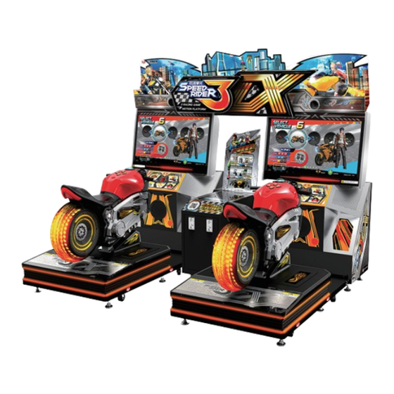
Summary of Contents for Baohui IGS Speed rider 3DX
- Page 1 User’s Manual ●Before installing and using this machine, please read this user manual carefully. ●Please follow all instructions in this user manual and pay attention to all descriptions to ensure that the machine is installed correctly. ●Please carefully store this user manual at where it can be easily accessed and read. Important ●The cabinet and parts of this machine are subject to change for further improvement.
-
Page 2: About This Manual
About this manual About this manual This User Manual describes how to install, set up, use and maintain this product. The purpose is to instruct machine operators and maintenance personnel to use this product correctly and safely. Please follow all safety and warning indications to prevent people from harm or machine from damage. -
Page 3: Safety Precautions
Safety Precautions Safety Precautions In order to prevent injury to the person who set up, use, and repair the product, as well as injury to the personal safety of others and damage to their property, please ensure to adhere to the following: Please Read ■... - Page 4 Safety Precautions Ordinary ■ Without the permission from our designated personnel, do not disassemble, change or remodel our products. CAUTION ■ Be sure to operate this product according to the instructions of this manual. Any inappropriate operation would damage this product and threaten the personal safety of players as well as onlookers.
-
Page 5: Table Of Contents
Table of contents Table of contents About this manual ..........1 4.3.10 Drain Valve Test ........44 4.3.11 Air Spring Test ........45 Safety precautions ..........2 4.3.12 Electric Jack Test ........46 Table of Contents ..........4 4.4 System Settings ..........46 Quick installation 4.4.1 Time Settings ......... - Page 6 Table of contents 5.3.2 Maintenance Instructions for the Camera...78 5.3.3 Maintenance Instructions for the Screen Lower Light Strips ........79 5.3.4 Maintenance Instructions for the Screen ... 80 5.3.5 Maintenance Instructions for the Air Vent Blowers..........82 5.3.6 Maintenance Instructions for the Subwoofer Light Board ........
-
Page 7: Quick Installation
Quick installation Quick installation Power settings Each power cord must be connected to a separate power outlet. Do not plug into the same power strip or use the same power connection. Connection and power Basic settings Open the coin box under the standby mode, and press the [TEST] button to enter [Operator Settings]. - Page 8 Quick installation • Example of connecting 4 cabinets (viewed from the front of the cabinet): Cabinet(L) Cabinet(R) Please setup the connection here. Please setup the connection here. Cabinet(L) Cabinet(R) Please setup the connection here. Please setup the connection here. B. Coin Rate Settings •...
-
Page 9: I/O Adjustments
Quick installation ■ I/O Adjustments Enter [Operator Settings] > [System Settings] > [I/O Adjustments] to run adjustment. • After clicking [Start Adjustments] , the options will stop at [Base parameters adjustments] . Place the vehicle in the center, release the brakes and throttle, click on the key to reset the motorcycle mid-point and reset the throttle, press down all the way on the left brake, press down all the way on the right brake, press down the motorcycle to the maximum... -
Page 10: Introduction Of The Cabinet
Introduction of the Cabinet Introduction of the Cabinet 1.1 List of the accessories After your purchase of this product, check if the following parts are all included. If any part is missing or damaged, contact your local distributor. Accessories Spec Picture Quantity 3m*1.5 square... - Page 11 Introduction of the Cabinet Accessories Spec Picture Quantity Coin box Screen box (left) Screen box (right) Machine name panel left light Machine name panel right light Center light box hardware stand Camera character acrylic (left) Camera character acrylic (right) Connector stand scanner description PVC foam board...
- Page 12 Introduction of the Cabinet Accessories Spec Picture Quantity Upper decorative PVC foam board left Upper decorative PVC foam board right Upper decorative PVC foam board center Cabinet connection bracket A Cabinet connection bracket Cover A Cabinet connection bracket Two Cabinet connection bracket Three Card description...
-
Page 13: An Overview Of The Cabinet
Introduction of the Cabinet 1.2 An overview of the cabinet ■ Viewed from the front and side Name of the parts... - Page 14 Introduction of the Cabinet 2706 /mm Name of the parts...
-
Page 15: Name Of The Parts
Introduction of the Cabinet 1.3 Name of the parts ■ Name of the exterior cabinet Cardboard (Left) DX Light box SR3 Light box 42"LCD Cardboard (Right) Acrylic board Connector stand 4'' Speaker PVC board Central connector stand Vehicle body Vent 8'' Speaker Left- and right-side guide light acrylic... - Page 16 Introduction of the Cabinet ■ Name of the exterior cabinet Light box Machine light box maintenance maintenance door door (in front of PVC board) Maintenance Door ( up ) Maintenance Door ( down ) Adjustment caster Power Inlet Movable caster Air compressor inlet Motherboard Vibration amplifier...
- Page 17 Introduction of the Cabinet ■ Name of the exterior cabinet Solenoid valve placement area Emergency button Break ( right ) Break ( left ) Handle S/Boost Arrow Keys Pedal sensor Pedal sensor (left) (right) Sensor Tail light Vehicle side light Tire light Vehicle bottom decorative light...
- Page 18 Machine Installation ■ Name of the interior parts Coin acceptor ■ Control panel Counter Volume Coin funnel Test Coin Box Service Control panel Air compressor Airbag regulator Drain control Water collection tray Transporting or moving the cabinet...
-
Page 19: Specification Of The Cabinet
Machine Installation 1.4 Specification of the cabinet Category Items Specification Size of the cabinet ( W)2700mmX( D)2177mmX( H)2188mm Concrete item Weight 868KG Power 110V/220V(To conform to local voltage ) 1P : 550W Power Maximum power 2600W 2P : 550W Air compressor(Coin Box) : 1500W Platform M01 (MH) Main cabinet... -
Page 20: Machine Installation
Machine Installation Machine Installation 2.1 Transporting or moving the cabinet After your purchase of this product, first move the cabinet to the location for installation and then connect the wires. When you transport, move and choose where to install make sure the following guidelines are followed: Reminders for transporting ■... - Page 21 Machine Installation Safety Precautions ■ Please check the voltage is 110V or 220V before the machine CAUTION connectes to the power supply, or it may cause a fire or electric shock. ■ Make sure to plug the fame into 110V or 220V main outlet to avoid fire and electric shock.
-
Page 22: Machine Assembly
Machine Installation 2.2 Machine assembly Install the decorative acrylic on the cabinet Move the 1 and 2P cabinets up against the according to the diagram. central connector stand, and then secure with screws from the inner side. Install the machine name light box on the cabinet according to the diagram. Secure the DX light box on the machine light Secure the SR3 light box on the machine box cabinet. - Page 23 Machine Installation Secure the PVC board and the fixing bracket on the cabinet. After positioning the vehicle body platform and the screen cabinet, secure with screws according to the diagram. Open the maintenance door and then secure U-shaped hook with screws from the inner side. Install the central decorative PVC board on the connector stand.
-
Page 24: Fastening The Cabinet
Machine Installation 2.3 Fastening the cabinet Fasten the cabinet with the leg leveler: Counterclockwise turn the leg leveler till a distance of at least 5mm is kept between the caster and the floor. 2.4 Power settings Each power cord must be connected to a separate power outlet. Do not plug into the same power strip or use the same power connection. - Page 25 Machine Installation • Example of connecting 4 cabinets (viewed from the front of the cabinet): Cabinet(L) Cabinet(R) Please setup the connection here. Please setup the connection here. Cabinet(L) Cabinet(R) Please setup the connection here. Please setup the connection here. B. Coin Rate Settings •...
-
Page 26: Setting The Group Number And Id Of The Cabinets
Machine Installation 2.6 Setting the group number and ID of the cabinets A. Setting the group number and ID of the cabinets In order to launch a multi-player game (a maximum of 4 cabinets is allowed), you must assign the cabinets into the same group but different ID. If four cabinets are connected, then appoint their ID as 1P, 2P, 3P, and 4P. - Page 27 Instructions of the game • Example of connecting 4 cabinets (viewed from the front of the cabinet): Cabinet(L) Cabinet(R) Please setup the connection here. Please setup the connection here. Cabinet(L) Cabinet(R) Please setup the connection here. Please setup the connection here. •...
-
Page 28: Instructions Of The Game
Instructions of the game Instructions of the game 3.1 Game introduction "Speed Rider 3DX" is a speed racing game. It is equipped with intuitive control such as infrared tilting, vibration sensory device, and left and right leaning, enabling players to experience an authentic control scenario. -
Page 29: Game Control
Instructions of the game 3.3 Game control ■ Instructions of the control buttons: In scene selection, press [Left] or [Right] to select the scene; use [Up] or [Down] to proceed in clockwise or anti- clockwise direction. Game control... - Page 30 Instructions of the game To instantly throttle, players can imitate the way to raise the front wheel of real motorcycles. Press the button for the BOOST. Leaning the motorcycle to the left and right end can make turns. Game control...
- Page 31 Instructions of the game The bending position can decrease wind resistance and increase the acceleration speed. When turning , press [Left Brake] can do drifting. For curves, press [Right Brake] to decelerate. When the game is in process press [Up], [Down] , [Right Brake] at the same time to stop the game.
- Page 32 Instructions of the game Use [Up], [Down], [Left], [Right] to select the text, then press the key to confirm. After scanning the QR code at the bottom right corner to share your results, press [Up] on the standby page (another token is required) and scan the QR code again to receive the mystery prize.
-
Page 33: Instruction Of The Game Display
Instructions of the game Go to the vehicle selection page and the prize will be displayed automatically. 3.4 Instruction of the game display Distance to destination Rank Time Player Distance to avatar destination Number of nitrogen Speed RPM gauge Instruction of the game display... -
Page 34: Using The Operator Settings
Using the Operator Settings Using the Operator Settings 4.1 Menu Structure Hardware Test I/O Test Screen Test Sound Test Lamp Test Connection Test Camera Test Counter Test Vibration Test Fan Speed Test Drain Valve Test Air Spring Test Electric Jack Test System Settings Time Settings Connection Settings... - Page 35 Using the Operator Settings Game setting defaults Name of the Setting Default Setting Available Setting Connection Setting→Group 0→99 Number Connection Setting→ID 1p,2p,3p,4p Fan Mode Settings Variable Variable,Constant Start the motion Start the motion with two feet,Start the Foot Panel Setting with two feet motion with one foot,Sensing Off Electric Jack Settings...
- Page 36 Using the Operator Settings Name of the Setting Default Setting Available Setting Sound Settings→Evening Volume 0%,10%,20%,30%,40%,50%,60%,70%, Setting→Master Volume 80%,90%,100% Sound Settings→Evening Volume 0%,10%,20%,30%,40%,50%,60%,70%, Setting→Standby Volume 80%,90%,100% Sound Settings→Evening Volume 0%,10%,20%,30%,40%,50%,60%,70%, Setting→Menu Volume 80%,90%,100% Sound Settings→Evening Volume 0%,10%,20%,30%,40%,50%,60%,70%, Setting→Vehicle Volume 80%,90%,100% Sound Settings→Evening Volume 0%,10%,20%,30%,40%,50%,60%,70%, Setting→Notification Volume...
-
Page 37: Using The Operator Settings
Using the Operator Settings Name of the Setting Default Setting Available Setting 5 Sec,10 Sec, 15 Sec,20 Sec,25 Sec,30 Flow Time Setting→Insert Token To 15 Sec Sec,35 Sec,40 Sec,45 Sec,50 Sec,55 Continue Sec,60 Sec 5 Sec,10 Sec, 15 Sec,20 Sec,25 Sec,30 Flow Time Setting→Standby For 10 Sec Sec,35 Sec,40 Sec,45 Sec,50 Sec,55... -
Page 38: Hardware Test
Using the Operator Settings 3 After completing the test, use [Up], [Down] keys to select [Exit] then press again to return to game. 4.3 Hardware Test You can enter [Hardware Test] to test if all software is normally functioning or not. 1 Enter [Operator Settings] >... -
Page 39: I/O Test
Using the Operator Settings 4.3.1 I/O Test In the page of [I/O Test] , you can run the testing for specific I/O application to see if it is normally functioning. Well-sensed devices will display in red or the sensed value: 1 Enter [Operator Settings] >... -
Page 40: Screen Test
Using the Operator Settings 3 After testing is completed, press the button and [Up] button at the same time, and you will leave this page. If the value of the throttle, brakes or tilt axis is not normal, enter [Operator Settings] >... -
Page 41: Sound Test
Using the Operator Settings 4.3.3 Sound Test In the page of [Sound Test] , you can test whether each sound track is normally functioning or not. 1 Enter [Operator Settings] > [Hardware Test] > [Sound Test]. 2 The tested sound track will keep playing the sound, and press the button again to discontinue the testing. -
Page 42: Connection Test
Using the Operator Settings 4 After completing the test, use [Up], [Down] keys to select [Back] then press again to return to previous menu. 4.3.5 Connection Test After you have assigned a group number for the cabinets to be connected and set up the ID, you can enter the page of [Connection Test] to test whether each cabinet of the same group is normally connected. -
Page 43: Camera Test
Using the Operator Settings sending the connection status of all cabinets. Possible connection status includes: Connected , Checking , Connection failed 3 After the testing is completed, press the button again to return to the previous menu. Notes: No matter how many cabinets are connected, the system will automatically run the testing for four cabinets (1P~4P). -
Page 44: Counter Test
Using the Operator Settings 4.3.7 Counter Test In the page of [Counter Test] , you can test whether the counter is normally functioning or not. 1 Enter [Operator Settings] > [Hardware Test] > [Counter Test] . 2 In the page of [Counter Test] , press the button, and the system will automatically run for 5 times (from 0 to 5). -
Page 45: Fan Speed Test
Using the Operator Settings 4.3.9 Fan Speed Test In the page of [Fan Speed Test] , you can test whether the Fan speed is normally functioning or not. 1 Enter [Operator Settings] > [Hardware Test] > [Fan Speed Test] . 2 After selecting [Fan Speed Test] and pressing the key, the system will automatically test fan from levels 1 to 4 (1/4 - 4/4). -
Page 46: Air Spring Test
Using the Operator Settings 4.3.11 Air Spring Test On the [Air Spring Test] page, you can test if the Air Spring is functioning properly. The testing steps are as follows: 1 Enter [Main Menu] > [Hardware Test] > [Air Spring Test] . 2 To do the Auto Test: After pressing the [Auto Test] button, the system will test the height of each air spring in sequence. -
Page 47: Electric Jack Test
Using the Operator Settings 4.3.12 Electric Jack Test On the [Electric Jack Test] page, you can test if the Electric Jack is functioning properly. The testing steps are as follows: 1 Enter [Main Menu] > [Hardware Test] > [Electric Jack Test] . 2 Press the button to start the test. -
Page 48: Time Settings
Using the Operator Settings 4.4.1 Time Settings On the [Time Settings] screen, you can set the system time as the time base for each point accumulation system. Attention: 1 If the store does not set up the time, then the system will use the time value of the machine as the default value. -
Page 49: Connection Settings
Using the Operator Settings 4.4.2 Connection Settings To connect each cabinet (a maximum of four cabinets are allowed), you need to complete the following settings. ► All cabinets to be connected should be appointed the same group number and a different ID. - Page 50 Using the Operator Settings 3 Setting the ID of the main cabinet: Select the ID by using [Up] and [Down] buttons. Then press the button to confirm. 4 You can use the [Up], [Down] keys to select [Network Information] , press enter the page, then check MAC Address, IP Address, Subnet Mask, Gateway are all correct.
-
Page 51: Country Settings
Using the Operator Settings 4.4.3 Country Settings In the page of [Country Settings], you can set your location, which will display on player’s information of the ranking list. 1 Enter [Operator Settings] > [System Settings] > [Country Settings] . 2 If you don't want to set up the Country, on the [Country Settings] page, use the [Up] , [Down] keys to select [Back] and press the key to return to the previous menu. -
Page 52: Password Settings
Using the Operator Settings 4.4.5 Password Settings On the [Password Settings] page, you will be able to change the default password to your own store's password. And the default password [0000] the set-up steps are as follows: 1 Enter [Operator Settings] > [System Settings] > [Password Settings] . 2 Go to the page and enter the original password first before entering the new password. -
Page 53: I/O Adjustments
Using the Operator Settings 5 After the new password has be entered, the words [Password changed successfully] will appear at the bottom in red. 6 After the password has been confirmed, use the [Up], [Down] keys to select [Back ] and press to return to the previous menu. - Page 54 Using the Operator Settings 3 When the cursor is pointing to [Base parameters adjustments] , then keep the motorcycle in the middle position, releasing the brake and throttle. Then press button. 4 Under the [Full Throttle] option, fill up the throttle and press the key to move on to the next reset option.
-
Page 55: Foot Panel Settings
Using the Operator Settings 4.4.7 Foot Panel Settings On the [Foot Panel Settings] page, you can adjust the pressure sensing settings. The setting steps are as follows: 1 Go to [Main Menu] > [System Settings] > [Foot Panel Settings] . 2 Use the [Up] and [Down] keys to select [Start the motion with two feet] , [Start the motion with one foot] , [Sensing off] , and then press the button. -
Page 56: Air Spring Adjustment
Using the Operator Settings 3 After the adjustment is complete, use the left and right brakes, the [Up] and [Down] keys, to select [Return to Previous Page] , press the button to return to the previous menu. 4.4.9 Air Spring Adjustment On the [Air Spring Adjustment ] page, you can adjust the Air Spring of the motorbike. -
Page 57: Fan Mode Settings
Using the Operator Settings 4.4.10 Fan Mode Settings On the [Fan Mode Settings] page, you can adjust the settings of the fan. The setting steps are as follows: 1 Go to [Main Menu] > [System Settings] > [Fan Mode Settings] . 2 Use the [Up] and [Down] keys to select [On] or [Off] , confirm and press the button. -
Page 58: Game Settings
Using the Operator Settings 4.5 Game Settings In the page of [Game Settings] , you can set up all related features of the game. 1 Enter [Operator Settings] > [Game Settings] , and the screen will display as below. 2 To enter the sub menu, use [Up], [Down] select item, and press the button to confirm. -
Page 59: Coin Rate Settings
Using the Operator Settings 4.5.1 Coin Rate Settings In the page of [Coin Rate Settings] , you can determine if free games are offered, and set up the required number of coins to start or continue the game: 1 Enter [Operator Settings] > [Game Settings] > [Coin Rate Settings] . 2 Use the [Up], [Down] keys to select [Free play] On/Off and start level, press key and use the [Up], [Down] keys to adjust, then press the key again to... -
Page 60: Difficult Settings
Using the Operator Settings 6 After the adjustment has been confirmed, use the [Up], [Down] keys to select [Back] , press the key to return to the previous menu. 4.5.3 Difficulty Settings In the [Difficulty Settings] , you can set up the level of the game . The default setting is [Normal] . -
Page 61: Number Of Laps
Using the Operator Settings 4.5.4 Number Of Laps On the [Number Of Laps] page, you can set up how many times the [Check Point] (increase time) must be passed in the game to reach the final destination. The default setting is [3 Check points]. The set-up steps are as follows: 1 Enter [Operator Settings] >... -
Page 62: Flow Time Settings
Using the Operator Settings 3 Option [Challenge in game player] refers to whether or not other players will be allowed to enter the battle randomly. Press the key, use the [Up], [Down] keys to adjust On/Off, then press the key again to confirm. 4 After the adjustment has been confirmed, use the [Up], [Down] keys to select [Back] , press the key to return to the previous menu. -
Page 63: Promotional Qr Code
Using the Operator Settings 4.5.7 Promotional QR Code Go to the [Promotional QR Code] page to insert your store's official website or other websites into the game page in the form of a QR code for promotional purposes. The set-up steps are as follows: 1 Enter [Operator Settings] >... - Page 64 Using the Operator Settings 4 To temporarily disable the promotional QR code, go to the option [Enable social network] and press the key, use the [Up], [Down] keys to adjust On/Off, then press the key again to confirm. 5 After the adjustment has been confirmed, use the [Up] , [Down] keys to select [Back] , press the key to return to the previous menu.
-
Page 65: Motion Default Settings
Using the Operator Settings 4.5.8 Motion Default Settings On the [Motion Default Settings] page, you can adjust the motion default settings. The setting steps are as follows: 1 Go to [Main Menu] > [Game Settings] > [Motion Default Settings ]. 2 Use the [Up] and [Down] keys to select [Comfort Mode] or [Power Mode] , press button to return to the previous menu. -
Page 66: Clothes Setting
Using the Operator Settings 4.5.10 Clothes Setting On the [Clothes Setting] page, you can adjust the settings of the Clothes Setting. The setting steps are as follows: 1 Go to [Main Menu] > [Game Settings] > [Clothes Setting] . 2 Use the [Up] and [Down] keys to select [Short sleeve] or [Long sleeve] , confirm and press the button. -
Page 67: Daily Income
Using the Operator Settings 4.6.1 Daily Income On the page of [Daily Income] , you can view daily income information. 1 Press the button to return to the previous menu. Description of Daily Income Items: Item Description Date Date of record Coin(s) Total number of coins inserted that day Total Game... -
Page 68: Monthly Income
Using the Operator Settings 4.6.2 Monthly Income On the page of [Monthly Income] , you can view Monthly income information. 1 Use the [Up], [Down] keys to move between pages, press the key to return to the previous menu. Description of Monthly Income Items: Item Description Date... -
Page 69: Total Income
Using the Operator Settings 4.6.3 Total Income On the page of [Total Income] , you can view the current total number of tokens, number of rounds, number of battles, game time, operation hours, and machine standby ratio. 1 Press the button to return to the previous menu. -
Page 70: System Reset
Using the Operator Settings 4.7 System Reset In the page of [System Reset] , you can set system data and auto reply to the default setting. 1 Enter [Operator Settings] > [System Settings] , Steps are as follows. 2 To enter the sub menu, move the cursor by using [Up] and [Down] buttons, and press the button to confirm. - Page 71 Using the Operator Settings 3 If you select [Yes] : if Clear was successful the words [Reset Complete] will appear in red. 4 If you select [No] : you will return to the previous menu directly. 5 If the password is entered incorrectly, the words [Incorrect password] will appear in red below.
-
Page 72: Restore Default Settings
Using the Operator Settings 4.7.2 Restore Default Dettings On the page of [Restore Default Settings] , you can reset the game settings to the default settings. 1 Enter [Operator Settings] > [System Reset] > [Restore Default Settings] . 2 Press the key at the option [Enter password], use the [Up], [Down] keys to set the password digit you would like to use, and press the key to confirm and... -
Page 73: Ranking Board Reset
Using the Operator Settings 4 If you select [No] : you will return to the previous menu directly. 5 If the password is entered incorrectly, the words [Incorrect password] will appear in red below. 6 If no adjustments are to be made, use the [Up], [Down] keys to select [Back] , and press the key to return to the previous menu. -
Page 74: Reset Player Photo
Using the Operator Settings 4 If you select [No] : you will return to the previous menu directly. 5 If no adjustments are to be made, use the [Up], [Down] keys to select [Back] , and press the key to return to the previous menu. 4.7.4 Reset Player Photo On the [Reset Player Photo] page, you can restore the avatar photo to the default setting. -
Page 75: Update Progress
Using the Operator Settings 4 If you select [No] : you will return to the previous menu directly. 5 If no adjustments are to be made, use the [Up], [Down] keys to select [Back], and press the key to return to the previous menu. 4.7.5 Update Progress On the [Update progress] page, you can check it there is an update for the latest version. -
Page 76: Maintenance And Repair
Using the Operator Settings Maintenance and Repair 5.1 Daily inspection To extend the life of this product, routinely maintain and inspect it. Exterior inspection: ● Check if warning labels are coming off, dirty or unrecognizable. If so, replace them immediately. ●... -
Page 77: Replacement Parts
Maintenance and repair 5.3 Replacing Parts 5.3.1 Maintenance Instructions for the Upper Light Box Light Strips Remove the decorative acrylic fixing screws. decorative acrylic Light Box Cover After unscrewing the screws of the acrylic, remove the light strips for maintenance. Replacing parts... - Page 78 Maintenance and repair light strip R e m o v e t h e l i g h t strip securing screws a n d p e r f o r m t h e maintenance. light box maintenance door Remove the fixing screws from the light b o x m a i n t e n a n c e...
-
Page 79: Maintenance Instructions For The Camera
Maintenance and repair 5.3.2 Maintenance Instructions for the Camera light box maintenance door Remove the fixing screws from the light b o x m a i n t e n a n c e door. camera back cover hardware Remove the camera back cover hardware. -
Page 80: Maintenance Instructions For The Screen Lower Light Strips
Maintenance and repair 5.3.3 Maintenance Instructions for the Screen Lower Light Strips screen's decorative acrylic Remove the screen's d e c o r a t i v e a c r y l i c fixing screws. light strip R e m o v e t h e l i g h t s t r i p s a n d t h e n begin the light strip maintenance. -
Page 81: Maintenance Instructions For The Screen
Maintenance and repair 5.3.4 Maintenance Instructions for the Screen Open the Rear Maintenance Door with the corresponding key, and detach the screen cables. Rear Maintenance Door Remove the screen frame fixing screws. Remove the screen f r a m e b a c k c o v e r fixing screws. - Page 82 Maintenance and repair Screen Frame Back Cover Remove the screen frame fixing screws and carefully remove t h e s c r e e n f r a m e back cover. After replacing the screen, reinstall the screen by reversing the steps.
-
Page 83: Maintenance Instructions For The Air Vent Blowers
Maintenance and repair 5.3.5 Maintenance Instructions for the Air Vent Blowers air vent acrylic Remove the air vent acrylic fixing screws. Remove the blower fixing frame. Remove and replace the blowers according to the diagram, once completed, reinstall b y r e v e r s i n g t h e steps. -
Page 84: Maintenance Instructions For The Subwoofer Light Board
Maintenance and repair 5.3.6 Maintenance Instructions for the Subwoofer Light Board Remove the subwoofer fixing screws and carefully remove the subwoofer mesh. subwoofer mesh Remove the light board fixing screws according to the diagram and then begin maintenance. Replacing parts... -
Page 85: Maintenance Instructions For The Left- And Right-Side Guide Light Boards
Maintenance and repair 5.3.7 Maintenance Instructions for the Left- and Right-Side Guide Light Boards Remove the subwoofer fixing screws and carefully remove the subwoofer mesh. subwoofer mesh Remove the fixing hardware of the left- and right-side guide lights according to the diagram. -
Page 86: Maintenance Instructions For The Air Compressor
Maintenance and repair 5.3.8 Maintenance Instructions for the Air Compressor Open the Maintenance Door with the corresponding key. Maintenance Door D e - p r e s s u r i z e t h e internal pressure of the air compressor, e n s u r e t h a t t h e p r e s s u r e v a l u e i s 0, then remove the... - Page 87 Maintenance and repair Remove the air compressor tray's securing screws. Pull forward the tray h a n d l e f r o m t h e front, and pull the air compressor out of the cabinet to perform the maintenance. tray handle Replacing parts...
-
Page 88: Maintenance Instructions For The Airbag Solenoid Valve
Maintenance and repair 5.3.9 Maintenance Instructions for the Airbag Solenoid Valve Remove the platform maintenance upper cover fixing screws and carefully remove the upper cover. upper cover A f t e r r e m o v i n g t h e s c r e w s t h a t l o c k t h e s o l e n o i d valve in place, the... -
Page 89: Maintenance Instructions For The Pedal Sensor
Maintenance and repair 5.3.10 Maintenance Instructions for the Pedal Sensor Remove the pedal sensor upper cover securing screws. pedal sensor upper cover Remove the pedal s e n s o r m o d u l e securing screws. pedal sensor module light strips After removing the acrylic fixing screws,... -
Page 90: Maintenance Instructions For The Light Strips At The Bottom Of The Vehicle
Maintenance and repair 5.3.11 Maintenance Instructions for the Light Strips at the Bottom of the Vehicle Remove the light box frame fixing screws and carefully take down from the side. light box frame Remove the light strip fixing brackets and then begin the light strip maintenance. -
Page 91: Maintenance Instructions For The Vehicle Side Light Cover
Maintenance and repair 5.3.12 Maintenance Instructions for the Vehicle Side Light Cover Remove the securing screws of the vehicle side plastic cover. vehicle side plastic cover Remove the side light cover fixing screws. Remove the securing screws on top of the light cover. -
Page 92: Maintenance Instructions For The Tire Decorative Hardware Light Board
Maintenance and repair 5.3.13 Maintenance Instructions for the tire decorative hardware light board R e m o v e t h e t i r e decorative hardware and acrylic. R e m o v e t h e t i r e d e c o r a t i v e p l a s t i c components. -
Page 93: Maintenance Instructions For The Tire Light Strips
Maintenance and repair Remove the light board securing screws, once completed, reinstall by reversing the steps. 5.3.14 Maintenance Instructions for the Tire Light Strips tire plastic components Remove the fixing s c r e w s o f t h e t i r e plastic components a c c o r d i n g t o t h e d i a g r a m a n d t h e n... -
Page 94: Maintenance Instructions For The Tail Light Board
Maintenance and repair 5.3.15 Maintenance Instructions for the Tail Light Board tire plastic components Remove the fixing s c r e w s o f t h e t i r e plastic components a c c o r d i n g t o t h e d i a g r a m a n d t h e n begin maintenance. -
Page 95: Maintenance Instructions For The Throttle/Brake Sensor
Maintenance and repair Remove the fuel tank cap from the top and perform the IO board maintenance. 5.3.17 Maintenance Instructions for the Throttle/Brake Sensor Remove the securing screws of the fuel tank cap. Remove the sensor fixing screws according to the diagram and then begin maintenance. -
Page 96: Maintenance Instructions For The Vehicle Movement Sensor
Maintenance and repair 5.3.18 Maintenance Instructions for the Vehicle Movement Sensor Remove the securing screws of the vehicle left-side plastic outer cover. plastic outer cover After replacing the vehicle movement sensor, reinstall by reversing the steps. Replacing parts... -
Page 97: Troubleshooting
Troubleshooting Troubleshooting Problem Solutions ■ Enter [Operator Settings] > [Hardware Test] > [I/O Test] to run The throttle, brakes or the testing. the tilt axis function do ■ If the testing does not respond, contact your local distributor to not work. replace the corresponding VR. - Page 98 ■ If the issue persists, please contact your local distributor. ◎ If any of the above mentioned problems is unsolvable, contact your local distributor. Distributor BAOHUI ELECTRONIC SCIENCE & TECHNOLOGY CO., LTD. Add: Room#C1/C3/C5,Star Carton City,No.143 East Yingxing Rd, Donghuan Street,Panyu District,Guangzhou China...
-
Page 99: Appendix 1: Warning Labels Of The Cabinet
Appendix 1: warning labels of the cabinet warning labels of the cabinet... -
Page 100: Appendix 2: Wiring Diagram Of The Cabinet
© 2020 Copyright All Rights Reserved, International Games System Co., Ltd. Software Developers INTERNATIONAL GAMES SYSTEM CO., LTD. http://www.igs.com.tw Distributor BAOHUI ELECTRONIC SCIENCE & TECHNOLOGY CO., LTD. Add: Room#C1/C3/C5,Star Carton City,No.143 East Yingxing Rd, Donghuan Street,Panyu District,Guangzhou China Tel: +86-20-23885180 23885868 Fax: +86-20-23885190 Http://www.baohuigame.net...
Need help?
Do you have a question about the IGS Speed rider 3DX and is the answer not in the manual?
Questions and answers