
Summary of Contents for CERUS INTERCEPT INT100
- Page 1 INTERCEPT Blood System ® Pathogen Inactivation Process ILLUMINATOR Operator Manual Software Version 6...
- Page 2 Cerus Corporation Cerus Europe B.V. 2550 Stanwell Drive Stationsstraat 79-D Concord, CA 94520 USA 3811 MH Amersfoort Made in USA The Netherlands www.interceptbloodsystem.com Cerus and INTERCEPT are trademarks of Cerus Corporation. MAN-EN 00601, v3.0...
- Page 3 INTERCEPT ILLUMINATOR INT100 Operator Manual Software Version 6 Illuminator Serial Number_________________ MAN-EN 00601, v3.0...
- Page 4 This page intentionally left blank. MAN-EN 00601, v3.0...
- Page 5 Master Table of Contents Master Table of Contents (Each Chapter has a Detailed Table of Contents) CHAPTERS PAGE What the Illuminator Does How to Use this Manual Illuminator Description How to Use the Illuminator Troubleshooting Maintenance, Transportation and Storage, Warranty and Service Specifications Appendix MAN-EN 00601, v3.0...
- Page 6 Master Table of Contents This page intentionally left blank. MAN-EN 00601, v3.0...
- Page 7 Chapter 1 – What the Illuminator Does Chapter 1 What the Illuminator Does SECTIONS PAGE What the Illuminator Does Intended Use of the Illuminator Indications for Use Contraindications for Use Notes to Transfusionists Warnings Cautions 1-11 MAN-EN 00601, v3.0...
- Page 8 Chapter 1 – What the Illuminator Does This page intentionally left blank. MAN-EN 00601, v3.0...
- Page 9 Chapter 1 – What the Illuminator Does Section 1.1 – What the Illuminator Does Section 1.1 What the Illuminator Does The INTERCEPT Illuminator delivers a controlled dose of Ultraviolet A (UVA) light to blood products, as part of the process to inactivate pathogens. The illuminator is used in conjunction with platelets and plasma in an INTERCEPT Processing Set.
- Page 10 Chapter 1 – What the Illuminator Does Section 1.2 – Intended Use of the Illuminator Section 1.2 Intended Use of the Illuminator The ‘illuminator’ refers to the INT100 INTERCEPT Illuminator. The INTERCEPT Illuminator is intended only for use in the pathogen inactivation process to deliver UVA light for the photochemical treatment of blood products.
- Page 11 Chapter 1 – What the Illuminator Does Section 1.3 – Indications for Use Section 1.3 Indications for Use Platelets and plasma treated with the INTERCEPT Blood System process are indicated for support of patients requiring transfusions, according to clinical practice guidelines. MAN-EN 00601, v3.0...
- Page 12 Chapter 1 – What the Illuminator Does Section 1.4 – Contraindications for Use Section 1.4 Contraindications for Use Use of platelets and / or plasma treated with the INTERCEPT Blood System process is contraindicated in patients with a history of allergic response to amotosalen or psoralens.
- Page 13 Chapter 1 – What the Illuminator Does Section 1.5 – Notes to Transfusionists Section 1.5 Notes to Transfusionists While laboratory studies of amotosalen processing with UVA light have shown a reduction in levels of certain viruses and bacteria, there is no pathogen inactivation process that has been shown to eliminate all pathogens.
- Page 14 Chapter 1 – What the Illuminator Does Section 1.6 – Warnings Section 1.6 Warnings The warning messages below will alert you to potential hazards that may cause personal injury. This includes conditions that would compromise pathogen inactivation results. Warning messages are listed according to the Section in which they appear. Chapter 3: ILLUMINATOR DESCRIPTION ...
- Page 15 Chapter 1 – What the Illuminator Does Section 1.6 – Warnings Make sure the barcodes and chamber position of each WARNING container are correctly entered into the illuminator. Section 4.4 - Scan Barcodes Partial illumination has not been validated for pathogen WARNING inactivation.
- Page 16 Chapter 1 – What the Illuminator Does Section 1.6 – Warnings Chapter 7: SPECIFICATIONS The use of accessories and cables other than those specified WARNING in this manual, as replacement parts for internal components, may result in increased emissions or decreased immunity of the illuminators.
- Page 17 Chapter 1 – What the Illuminator Does Section 1.7 – Cautions Section 1.7 Cautions The cautions below alert you to any conditions that could affect the blood product quality, damage the illuminator, or make the illuminator sound an alarm unnecessarily. Cautions are listed according to the Section in which they appear.
- Page 18 Chapter 1 – What the Illuminator Does Section 1.7 – Cautions Chapter 6: MAINTENANCE, TRANSPORTATION AND STORAGE, WARRANTY AND SERVICE Do not use the illuminator if there is condensation on it. CAUTION Humidity higher than 80% may shorten the life of instrument components.
- Page 19 Chapter 2 – How to Use this Manual Chapter 2 How to Use this Manual SECTIONS PAGE Getting Started Symbols Conventions Used in this Manual MAN-EN 00601, v3.0...
- Page 20 Chapter 2 – How to Use this Manual Section 2.1 – Getting Started This page intentionally left blank. MAN-EN 00601, v3.0...
- Page 21 Chapter 2 – How to Use this Manual Section 2.1 – Getting Started Section 2.1 Getting Started This Section explains how to use the illuminator manual. This manual gives detailed information about the use of the INTERCEPT Illuminator. It complements the package inserts that accompany the INTERCEPT Processing Sets.
- Page 22 Chapter 2 – How to Use this Manual Section 2.1 – Getting Started • Chapter 6 Maintenance, Transportation and Storage, Warranty and Service This details cleaning and general maintenance and provides information on how to store and move the illuminator. It contains the warranty statement and service instructions.
- Page 23 Chapter 2 – How to Use this Manual Section 2.2 – Symbols Section 2.2 Symbols Symbols Throughout the manual the following symbols have been used. Used in This Each symbol and meaning is shown below: Manual Symbol What the Symbol Means ...
- Page 24 Chapter 2 – How to Use this Manual Section 2.2 – Symbols Symbols The following symbols are used on the outer shipping carton of the Used on the illuminator: Illuminator Packaging Symbol What the Symbol Means and Instructions “Catalogue number” “Serial number”...
- Page 25 Chapter 2 – How to Use this Manual Section 2.2 – Symbols Symbol What the Symbol Means and Instructions Product Safety Certification reflecting compliance with electrical safety standards. Symbols The following symbols are used on the illuminator: Used on the Illuminator Symbol What the Symbol Means...
- Page 26 Chapter 2 – How to Use this Manual Section 2.2 – Symbols Symbol What the Symbol Means USB printer port (rear of illuminator) Backspace, Delete or page back Advance or page forward This marking reflects compliance with the Medical Devices Directive 93/42/EEC issued by the Council of the European Communities.
- Page 27 Chapter 2 – How to Use this Manual Section 2.3 – Conventions Used in this Manual Section 2.3 Conventions Used in this Manual When messages from the illuminator screen are quoted in the manual, they will appear in bold type and quote marks, for example: ‘Select a function’...
- Page 28 Chapter 2 – How to Use this Manual This page intentionally left blank. 2-10 MAN-EN 00601, v3.0...
- Page 29 Chapter 3 – Illuminator Description Chapter 3 Illuminator Description SECTIONS PAGE Light System Product Identification and Traceability Illuminator Front Panel Description Color Screen Status Lights Barcode Scanner Buttons Function Buttons 3-10 Keypad Buttons 3-12 Backspace and Advance 3-13 Illumination Door and Drawer 3-14 User Access Levels 3-18...
- Page 30 Chapter 3 – Illuminator Description SECTIONS PAGE Export Data 3-40 Export All Treatments 3-42 Export Treatments in Date Range 3-43 Export All Service Data 3-44 Export Service Data in Date Range 3-45 Data Management System 3-47 Change Password 3-49 Features for Safety and Function 3-52 3.10 Computer Connections...
- Page 31 Chapter 3 – Illuminator Description Section 3.1 – Light System Section 3.1 Light System The INTERCEPT Illuminator provides a controlled dose of Ultraviolet A (UVA) light for the INTERCEPT pathogen inactivation process. It contains fluorescent bulbs above and below a clear tray where blood products are placed.
- Page 32 Chapter 3 – Illuminator Description Section 3.2 – Product Identification and Traceability Section 3.2 Product Identification and Traceability The illuminator will recognize and is compatible with the following barcode formats: 1. Codabar (including Monarch 11 and UKBTS) • 10 numeric characters : 0 through 9 •...
- Page 33 Chapter 3 – Illuminator Description Section 3.3 – Illuminator Section 3.3 Illuminator The illuminator has two main areas of interest to the operator: • the front panel, where the operator controls are located. • the door and drawer, where blood products are placed for illumination.
- Page 34 Chapter 3 – Illuminator Description Section 3.4 – Front Panel Description Section 3.4 Front Panel Description The front panel of the illuminator consists of separate parts as shown in the picture below. The buttons used to control operation are on either side of the screen. Each of these parts is explained below.
- Page 35 Chapter 3 – Illuminator Description Section 3.4 – Front Panel Description Screen Symbols Function Function Illumination Printing Illuminator settings Enter Username/Enter Password Date/Time Illuminator Identification Exporting Service Data Exporting Treatment Records Configurations Service Tasks Exporting Languages Messages appear in the middle of the screen. In addition to routine operating screens, there are three types of message screens: Error, Information, and Confirmation.
- Page 36 Chapter 3 – Illuminator Description Section 3.4 – Front Panel Description Screen Symbols Type of Message Error Information Confirmation Red Screen System Issue Barcode symbols Status Lights The status lights refer to the small round lights on the front panel of the illuminator.
- Page 37 Chapter 3 – Illuminator Description Section 3.4 – Front Panel Description Barcode At the front of the illuminator is a barcode scanner. Barcodes are Scanner scanned into the illuminator by pointing the scanner at the barcode and pressing the trigger. Barcode Scanner Barcodes are used to track blood products through the...
- Page 38 Chapter 3 – Illuminator Description Section 3.4 – Front Panel Description There are three types of buttons on the front panel of the illuminator: • Arrow buttons — up and down arrow buttons allow you to scroll through the screen choices. •...
- Page 39 Chapter 3 – Illuminator Description Section 3.4 – Front Panel Description NOTE: Press the function buttons next to the screen symbols. Screen Symbol Labels and Use Back/Edit Use this button to return to the previous screen or to edit information. Cancel/Cancel treatment Use this button to: 1.
- Page 40 Chapter 3 – Illuminator Description Section 3.4 – Front Panel Description Keypad Buttons Keypad These buttons are on the left side of the screen. They may be used to enter information if a barcode cannot be scanned. NOTE: If desired, the keypad may be disabled to prevent manual treatment data entry.
- Page 41 Chapter 3 – Illuminator Description Section 3.4 – Front Panel Description Backspace There are also backspace () and advance () buttons on the and Advance keypad as shown below in the previous figure: • The backspace () button will delete the last number or letter only.
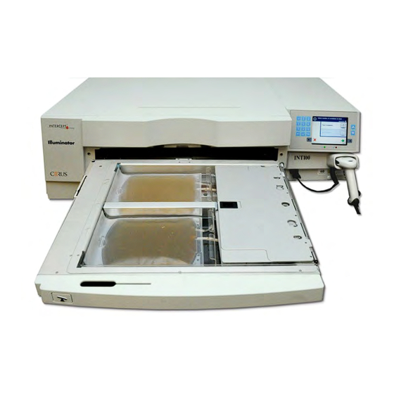
- Page 42 Chapter 3 – Illuminator Description Section 3.5 – Illumination Door and Drawer Section 3.5 Illumination Door and Drawer The door that extends across the front of the illuminator opens down. Inside, a drawer pulls out. The clear tray where illumination is performed is held in the drawer.
- Page 43 Chapter 3 – Illuminator Description Section 3.5 – Illumination Door and Drawer One blood product and processing set fits in the front chamber, chamber 1. The blood product in the illumination container goes on the left side of the chamber, with the rest of the set on the right side of the chamber.
- Page 44 Chapter 3 – Illuminator Description Section 3.5 – Illumination Door and Drawer NOTE: You can illuminate two containers at the same time, but they must contain the same type of set code. For example, you cannot illuminate a large volume and a small volume platelet set during the same illumination.
- Page 45 Do not attempt to service the UVA light sources or open areas of the illuminator which are not described in this operating manual. Contact a Cerus-authorized service company or representative for assistance. ...
- Page 46 The illuminator is designed with three user access levels: Operator, Administrator, and Service. The Service features are accessible only by a Cerus authorized field service engineer. The table below contains a summary of the functionality available within each access level.
- Page 47 Assign barcode formats Calibrate device Establish first administrator account Accessible only by Cerus authorized field service engineer. Applicable if operator function is required to use a password. X = Access allowed. --- = Access not allowed. 3-19 MAN-EN 00601, v3.0...
- Page 48 ‘Service’ accounts have the ability to Only ‘Administrator’ access the ‘Illuminator Settings’ screen. Your authorized Cerus Service representative will assist you to set up the first Administrator account. Before you are able to select the setting, you must access the ‘Select a setting’...
- Page 49 Chapter 3 – Illuminator Description Section 3.7 – Illuminator Settings • Alternatively, you may scan your username via the barcode scanner. If the barcode scanner is used, you will not need to press ‘Enter’ and there will not be a confirmation screen. •...
- Page 50 Chapter 3 – Illuminator Description Section 3.7 – Illuminator Settings • The ‘Select an option’ screen will appear. Select the ‘Illuminator Settings’ option and press the ‘Enter’ button. The ‘Select a setting’ screen will appear. Use the following steps to access the desired illuminator settings option or press the ‘Back’...
- Page 51 Chapter 3 – Illuminator Description Section 3.7 – Illuminator Settings • Use the arrow buttons at the right of the screen to choose the date format. Your choices are month/day/year, day/month/year or year/month/day. • Press the ‘Enter’ button to select the format. The ‘Enter date’ screen will appear.
- Page 52 Chapter 3 – Illuminator Description Section 3.7 – Illuminator Settings • Press the ‘Enter’ button after every entry. A confirmation screen will appear once you have entered all the data for date and time. • Press the ‘OK’ button to confirm the date and time. The ‘Select a setting’...
- Page 53 Chapter 3 – Illuminator Description Section 3.7 – Illuminator Settings • Press the ‘OK’ button to confirm the language choice. The ‘Select a setting’ screen will appear. Illuminator The illuminator identification setting allows you to enter an instrument Identification identification number such as a serial number. To enter the identification number, perform the following: •...
- Page 54 Chapter 3 – Illuminator Description Section 3.7 – Illuminator Settings • If the number is correct, press the ‘OK’ button to confirm the number. The ‘Select a setting’ screen will appear. Configurations The Configurations setting allows you to: • Set printing options: report printing, auto-printing, and label printing •...
- Page 55 Chapter 3 – Illuminator Description Section 3.7 – Illuminator Settings • The ‘Select a printer configuration setting’ screen will appear. • Use the arrow buttons to choose the ‘Report Printer’ option. • Press the ‘Enter’ button to select the ‘Report Printer’ option. The ‘Select a report printer option’...
- Page 56 Chapter 3 – Illuminator Description Section 3.7 – Illuminator Settings From the ‘Select a configuration setting’ screen, use the arrow buttons Auto Printing to choose the ‘Configure Printing’ option. • Press the ‘Enter’ button to select the ‘Configure Printing’ option. •...
- Page 57 Chapter 3 – Illuminator Description Section 3.7 – Illuminator Settings • Use the arrow buttons to choose either ‘On’ or ‘Off’. Selecting the ‘On’ option will automatically print the last treatment record(s) during the container unloading. If not using Auto- Printing, select the ‘Off’...
- Page 58 Chapter 3 – Illuminator Description Section 3.7 – Illuminator Settings Label Printer An illumination label will be printed after every treatment and must be applied to the illumination containers before they are removed from the illuminator. This label provides the following: •...
- Page 59 Chapter 3 – Illuminator Description Section 3.7 – Illuminator Settings To configure the number of labels to print, perform the following: • From the ‘Select a configuration setting’ screen, use the arrow buttons to choose the ‘Configure Printing’ option. • Press the ‘Enter’ button to select the ‘Configure Printing’ option.
- Page 60 Chapter 3 – Illuminator Description Section 3.7 – Illuminator Settings • Use the arrow buttons to choose ‘Platelets’ or ‘Plasma’. Press the ‘Enter’ button to select component. The ‘Enter the number of platelets/plasma labels’ screen will appear. • Use the keypad to enter the desired quantity (0 - 6) of labels to be printed.
- Page 61 Operator or Administrator. NOTE: The Service account option is accessible only by a Cerus- authorized field service engineer. This option is disabled for Administrators. • Use the arrow buttons to select the account type, Operator or Administrator.
- Page 62 Chapter 3 – Illuminator Description Section 3.7 – Illuminator Settings The ‘Add account’ screen will appear. Enter the username for the account, either by scanning a barcode or by entering the username manually with the keypad. (Refer to Section 4.2.) Press the ‘Enter’...
- Page 63 Chapter 3 – Illuminator Description Section 3.7 – Illuminator Settings • Enter the password for the account, either by scanning a barcode or by entering the password manually with the keypad. (Refer to Section 4.2.) Press the ‘Enter’ button if the password is manually entered.
- Page 64 Chapter 3 – Illuminator Description Section 3.7 – Illuminator Settings Disable Use to disable an account so that it is no longer a valid username. Account CAUTION Once an account has been disabled, it cannot be reactivated. Furthermore, the username cannot be reused. •...
- Page 65 Chapter 3 – Illuminator Description Section 3.7 – Illuminator Settings • The ‘Confirm username’ pop-up window will appear if the username was manually entered. If the manually-entered username is incorrect, press the ‘Edit’ button and correct it. • If the manually-entered username is correct, press the ‘OK’ button.
- Page 66 Chapter 3 – Illuminator Description Section 3.7 – Illuminator Settings • Use the arrow buttons to choose the ‘Reset Password’ option. Press the ‘Enter’ button to select the ‘Reset Password’ option. • The ‘Enter username’ screen will appear. Enter the username of the account whose password is to be reset either by scanning a barcode or by entering the username manually with the keypad.
- Page 67 Chapter 3 – Illuminator Description Section 3.7 – Illuminator Settings • Upon successful completion, the ‘Select an option’ screen will appear. Password Use to set the number of days that a user’s password is valid. Expiry Options are disabled (no expiration), 30 days, 90 days, or 180 days. •...
- Page 68 Chapter 3 – Illuminator Description Section 3.7 – Illuminator Settings • The ‘Configure password expiry time’ screen will appear. • Use the arrow buttons to choose ‘Disable,’ ‘30 days,’ ’90 days,’ or ‘180 days’. Press the ‘Enter’ button to choose one of the options.
- Page 69 Chapter 3 – Illuminator Description Section 3.7 – Illuminator Settings From the ‘Select a configuration setting’ screen, use the arrow buttons to choose the ‘Export Data’ option. • Press the ‘Enter’ button to select the ‘Export Data’ option. The ‘Select Data To Export’ screen will appear. The following sections detail each of the export data options.
- Page 70 Chapter 3 – Illuminator Description Section 3.7 – Illuminator Settings Export All Use ‘Export All Treatments’ to export all treatment records in the system Treatments memory to a host computer. • From the ‘Select Data To Export’ screen, use the arrow buttons to choose the ‘Export All Treatments’...
- Page 71 Chapter 3 – Illuminator Description Section 3.7 – Illuminator Settings Export Use to export treatment records within a specified date range to a host Treatments in computer. Date Range • From the ‘Select Data To Export’ Screen, use the arrow buttons to choose the ‘Export Treatments in Date Range’...
- Page 72 Chapter 3 – Illuminator Description Section 3.7 – Illuminator Settings Export All Use ‘Export All Service Data’ to export all service data to a host Service Data computer. • From the ‘Select Data To Export’ screen, use the arrow buttons to choose the ‘Export All Service Data’...
- Page 73 Chapter 3 – Illuminator Description Section 3.7 – Illuminator Settings Export Service Use ‘Export Service Data in Date Range’ to export service data Data in Date within a specified date range to a host computer. Range • From the ‘Select Data to Export’ screen, use the arrow buttons to choose the ‘Export Service Data in Date Range’...
- Page 74 Chapter 3 – Illuminator Description Section 3.7 – Illuminator Settings • If the data entered is incorrect, press the ‘Edit’ button. The ‘Specify date range’ screen will appear. Use the arrow buttons and the keypad to edit the date range and correct •...
- Page 75 Chapter 3 – Illuminator Description Section 3.7 – Illuminator Settings Data Do not connect the Illuminator to an open network. If using Management optional devices, such as ‘Data Management System’, only System connect the illuminator to a firewall-protected network. If your facility is using a data management system, set the configuration as described below.
- Page 76 Chapter 3 – Illuminator Description Section 3.7 – Illuminator Settings • Use the keypad to enter the TCP/IP address of the illuminator. • Press the ‘Enter’ button when the address has been entered. A confirmation screen will appear. • If the address is incorrect, press the ‘Edit’ button to return to the ‘Enter illuminator TCP/IP address’...
- Page 77 Chapter 3 – Illuminator Description Section 3.8 – Change Password Section 3.8 Change Password Any user can change their own account password after providing the appropriate credentials. The new password must be different from the current password. Valid passwords are 3 to 17 characters in length and are limited to alphabetic characters, digits, and the special characters “-“, “+”, “*”, “$”, “.”, “/”, and “:”.
- Page 78 Chapter 3 – Illuminator Description Section 3.8 – Change Password • The ‘Select an option’ screen will appear. Select the ‘Change Password’option and press the ‘Enter’ button. The ‘Enter New Password’ screen will appear. • Enter the new password either by scanning a barcode or by entering the password manually with the keypad.
- Page 79 Chapter 3 – Illuminator Description Section 3.8 – Change Password • The ‘Confirm password’ pop-up window will appear if the password was manually entered. If the manually-entered password is incorrect, press the ‘Edit’ button and correct it. • If the manually-entered password is correct, press the ‘OK’ button.
- Page 80 Chapter 3 – Illuminator Description Section 3.9 – Features for Safety and Function Section 3.9 Features for Safety and Function A microprocessor controls the illuminator. The illuminator also contains: • Air flow sensor — to make sure that the fan is working. •...
- Page 81 Chapter 3 – Illuminator Description Section 3.10 – Computer Connections Section 3.10 Computer Connections There are three connectors on the rear of the illuminator. Refer to Section 7.3 for details. NOTE: There are panels on each side of the illuminator that have no customer serviceable parts.
- Page 82 Chapter 3 – Illuminator Description Section 3.11 – Questions and Answers Section 3.11 Questions and Answers Q & A Whom should you contact if the illuminator is damaged? • If you notice the illuminator is damaged, contact your authorized service representative. Please refer to the front of this manual for contact details.
- Page 83 Chapter 3 – Illuminator Description Section 3.11 – Questions and Answers Q & A What should you do if the treatment times in your illuminator are consistently at the upper end of the range in Section 3.5? • The correct dose of light is being administered to the blood product, so pathogen inactivation is being appropriately achieved.
- Page 84 Chapter 3 – Illuminator Description This page intentionally left blank. 3-56 MAN-EN 00601, v3.0...
- Page 85 Chapter 4 – How to Use the Illuminator Chapter 4 How to Use the Illuminator SECTIONS PAGE Introduction Turn On the Illuminator and Enter Credentials Load Processing Set(s) Scan Barcodes 4-11 Repeat Set Loading for Container 2 4-13 Begin Illumination Process 4-14 Illumination Interruption 4-15...
- Page 86 Chapter 4 – How to Use the Illuminator This page intentionally left blank. MAN-EN 00601, v3.0...
- Page 87 Chapter 4 – How to Use the Illuminator Section 4.1 – Introduction Section 4.1 Introduction This chapter will guide you through a complete treatment cycle with the illuminator. A summary of operator steps is given in the Appendix. Illumination is one step in the INTERCEPT Blood System process. Refer to the ‘Directions for Use’...
- Page 88 Chapter 4 – How to Use the Illuminator Section 4.2 – Turn On the Illuminator and Enter Credentials Section 4.2 Turn On the Illuminator and Enter Credentials CAUTION Use care not to block the air vents of the illuminator during operation.
- Page 89 Chapter 4 – How to Use the Illuminator Section 4.2 – Turn On the Illuminator and Enter Credentials 5. If you have a barcode for username identification, scan it. If a barcode is not available, enter the identification manually. To enter your username manually, perform the following steps: •...
- Page 90 Chapter 4 – How to Use the Illuminator Section 4.3 – Load Processing Set(s) Section 4.3 Load Processing Set(s) 1. Access the ‘Select an Option’ screen (refer to Section 4.2), then use the arrow buttons to select the ‘Run Treatment’ option. 2.
- Page 91 Chapter 4 – How to Use the Illuminator Section 4.3 – Load Processing Set(s) 5. Open the front door of the illuminator. NOTE: If the door is not opened, then an information screen will appear to remind you to open the door. 6.
- Page 92 Chapter 4 – How to Use the Illuminator Section 4.3 – Load Processing Set(s) All materials containing platelets or plasma (including tubing) must WARNING: be placed within the large compartment of the illuminator tray for adequate treatment to occur. The INTERCEPT Blood System is validated with unimpeded light transmission through the tray and the illumination container with the blood component.
- Page 93 Chapter 4 – How to Use the Illuminator Section 4.3 – Load Processing Set(s) 11. Place the other containers into the right-hand side of the front chamber 1 so that the final storage container label is facing up. NOTE: Ensure that the containers in the right-hand side of the chamber remain secure.
- Page 94 Chapter 4 – How to Use the Illuminator Section 4.3 – Load Processing Set(s) NOTE: If you are treating two blood products, you may load the second processing set into the rear chamber 2 at this time or after scanning the barcodes for the first set.
- Page 95 Chapter 4 – How to Use the Illuminator Section 4.4 – Scan Barcodes Section 4.4 Scan Barcodes The ‘Enter treatment data for container 1’ screen will appear. 1. Scan the barcodes from the final storage container in the following order: Symbol Description Barcode 1...
- Page 96 Chapter 4 – How to Use the Illuminator Section 4.4 – Scan Barcodes 2. If the barcode cannot be scanned, you may enter the information manually by performing the following: • Use the keypad to enter the human-readable barcode. Special characters may be entered by pressing the ‘l’...
- Page 97 Chapter 4 – How to Use the Illuminator Section 4.5 – Repeat Set Loading for Container 2 Section 4.5 Repeat Set Loading for Container 2 If two containers have been selected for treatment, the ‘Enter treatment data for container 2’ screen will appear. Follow previous steps in Sections 4.3 and 4.4 to load the second set into the illuminator tray and scan barcodes, placing second container in the rear chamber 2.
- Page 98 Chapter 4 – How to Use the Illuminator Section 4.6 – Begin Illumination Process Section 4.6 Begin Illumination Process The ‘Running’ screen will automatically appear. NOTE: The blue bar moves to the right as the illumination progresses and is based on the target dose.
- Page 99 Chapter 4 – How to Use the Illuminator Section 4.7 – Illumination Interruption Section 4.7 Illumination Interruption CAUTION Illumination should not be interrupted, unless it is absolutely essential. It will result in improperly treated blood product(s) that should be discarded. 1.
- Page 100 Chapter 4 – How to Use the Illuminator Section 4.8 – Unload the Processing Set(s) Section 4.8 Unload the Processing Set(s) When the illumination of the blood product(s) has finished, the ‘Complete’ screen, which has an orange background, will appear. •...
- Page 101 Chapter 4 – How to Use the Illuminator Section 4.8 – Unload the Processing Set(s) • The screen will start counting the elapsed number of minutes, after the illumination has been completed. • The agitator will continue shaking the containers for platelet products but stop for plasma products.
- Page 102 Chapter 4 – How to Use the Illuminator Section 4.8 – Unload the Processing Set(s) Refer to the Instructions for Use in the INTERCEPT Processing Set for the next steps in the process. 1. Press the ‘Treatment’ button. The ‘Enter username’ screen will Process appear Additional...
- Page 103 Chapter 4 – How to Use the Illuminator Section 4.9 – Optional Printing Treatment Reports and Additional Labels Section 4.9 Optional Printing Treatment Reports and Additional Labels When the illuminator is configured to print reports (refer to Section 3.7, Illuminator Settings, for details), the following options are available: •...
- Page 104 Chapter 4 – How to Use the Illuminator Section 4.9 – Optional Printing Treatment Reports and Additional Labels All of the following printing options are accessible from the ‘Select a report to print’ screen. To access this screen, perform the following: 1.
- Page 105 Chapter 4 – How to Use the Illuminator Section 4.9 – Optional Printing Treatment Reports and Additional Labels 3. If this screen is incorrect, press the ‘Back’ button. The ‘Select a report to print’ screen will appear. Use the arrow buttons to choose the ‘Specific Treatment’...
- Page 106 Chapter 4 – How to Use the Illuminator Section 4.9 – Optional Printing Treatment Reports and Additional Labels Specific The Specific Treatment option refers to a selected product treated by the illuminator. To print this report, perform the following: Treatment 1.
- Page 107 Chapter 4 – How to Use the Illuminator Section 4.9 – Optional Printing Treatment Reports and Additional Labels 5. If the report is incorrect, press the ‘Back’ button to return to the ‘Select a treatment to print’ screen. Repeat the steps to choose the desired treatment to print.
- Page 108 Chapter 4 – How to Use the Illuminator Section 4.9 – Optional Printing Treatment Reports and Additional Labels 5. Use the arrow buttons to choose the desired date. If the date is not listed on the screen, press the advance () or backspace () buttons on the keypad to display the next page(s) of dates.
- Page 109 Chapter 4 – How to Use the Illuminator Section 4.9 – Optional Printing Treatment Reports and Additional Labels 5. Use the keypad to enter the ‘From’ date. Then, use the arrow buttons to advance to the ‘To’ date. Use the keypad to enter the ‘To’...
- Page 110 Chapter 4 – How to Use the Illuminator Section 4.9 – Optional Printing Treatment Reports and Additional Labels Print To print additional labels, perform the following: Additional Labels From the ‘Select a function’ screen, use the arrow buttons to choose the ‘Print Records’ option. 2.
- Page 111 Chapter 4 – How to Use the Illuminator Section 4.9 – Optional Printing Treatment Reports and Additional Labels 6. Press the ‘Enter’ button to select the desired treatment. The ‘Print the selected treatment labels’ screen will appear. 7. Press the ‘Print’ button to select this option. A confirmation screen will appear.
- Page 112 Chapter 4 – How to Use the Illuminator Section 4.10 – Change Users Before the Next Illumination Section 4.10 Change Users Before the Next Illumination Cycle If a different operator is performing the treatment process, perform the following: 1. Press the ‘Function’ button on the ‘Unload containers’ screen. The ‘Select a function’...
- Page 113 Chapter 4 – How to Use the Illuminator Section 4.11 – Turn Off the Illuminator Section 4.11 Turn Off the Illuminator If you want to turn off the illuminator: 1. Press the ‘Function’ button on the ‘Unload containers’ screen. The ‘Select a function’ screen will appear. 2.
- Page 114 Chapter 4 – How to Use the Illuminator Section 4.12 – Questions and Answers Section 4.12 Questions and Answers Q & A What will happen if the self-tests are not successful? • If the self-tests are not successful, an error message will appear on the screen with additional instructions.
- Page 115 Chapter 4 – How to Use the Illuminator Section 4.12 – Questions and Answers Q & A What should you do if one of the chambers cannot be used? • When one of the chambers cannot be used, you may use the other chamber, if the ‘Run Treatment’...
- Page 116 Chapter 5 – Troubleshooting Chapter 5 Troubleshooting SECTIONS PAGE Introduction Summary of Questions and Answers Error Messages System Issue Messages 5-23 Confirmation Messages 5-24 Information Messages 5-25 5 - 1 MAN-EN 00601, v3.0...
- Page 117 Chapter 5 – Troubleshooting This page intentionally left blank. 5 - 2 MAN-EN 00601, v3.0...
- Page 118 Chapter 5 – Troubleshooting Section 5.1 - Introduction Section 5.1 Introduction During an INTERCEPT procedure, a “pop-up” message may describe events ranging from errors to general procedure information. These are the types of messages that can occur during a procedure: Screen Symbols What the Symbol Means Error...
- Page 119 Chapter 5 – Troubleshooting Section 5.2 – Summary of Questions and Answers Section 5.2 Summary of Questions and Answers The following is a list of the Questions and Answers used in the Operator’s Manual. Chapter 3: ILLUMINATOR DESCRIPTION Q & A Whom should you contact if the illuminator is damaged? •...
- Page 120 Chapter 5 – Troubleshooting Section 5.2 – Summary of Questions and Answers Q & A What should you do if the treatment times in your illuminator are consistently at the upper end of the range in Section 3.5? • The correct dose of light is being administered to the blood product, so pathogen inactivation is being appropriately achieved.
- Page 121 Chapter 5 – Troubleshooting Section 5.2 – Summary of Questions and Answers Q & A What should you do if one of the chambers cannot be used? • When one of the chambers cannot be used, you may use the other chamber, if the ‘Run Treatment’...
- Page 122 Chapter 5 – Troubleshooting Section 5.2 – Summary of Questions and Answers Chapter 5: TROUBLESHOOTING What should you do if the System Issue screen appears? Q & A • The System Issue message is used to alert the operator of critical issues with the illuminator.
- Page 123 Chapter 5 – Troubleshooting Section 5.3 – Error Messages Section 5.3 Error Messages The error messages will be indicated by a red-bordered pop-up screen and will have an icon with an exclamation point in a yellow diamond. The error messages, or alarm messages, account for the largest portion of the possible pop-up messages in this Section.
- Page 124 Chapter 5 – Troubleshooting Section 5.3 – Error Messages Agitator Message This occurs if: Service Light There is an issue with the The agitator is stopped or is On after ‘Cancel’ is agitator. Treatment must moving slowly. Contact your be canceled. Contact authorized service selected service for assistance.
- Page 125 Chapter 5 – Troubleshooting Section 5.3 – Error Messages Bulbs Message This occurs if: Service Light The bulbs are not Bulbs need to be replaced. On after ‘Continue’ is working properly in Contact your authorized service chamber(s) (1, 2 or representative for assistance.
- Page 126 Chapter 5 – Troubleshooting Section 5.3 – Error Messages Data Entry Message This occurs if: Service Light The alphanumeric string is There are too many characters in too long to fit in the data an entry field. The entry field is field.
- Page 127 Chapter 5 – Troubleshooting Section 5.3 – Error Messages Data Entry Message This occurs if: Service Light Checksum Error. The selected format for the data The data entered cannot field includes a checksum and be verified. Please press the checksum does not match ‘Cancel’...
- Page 128 Chapter 5 – Troubleshooting Section 5.3 – Error Messages Drawer Message This occurs if: Service Light Open the door and The drawer is closed before the On after ‘Cancel’ is drawer and complete treatment data has been entered. entry of treatment data. Open the drawer and enter the selected Touch ‘OK’...
- Page 129 Chapter 5 – Troubleshooting Section 5.3 – Error Messages Message This occurs if: Service Light The fan is not working The fan is not working properly, or On after ‘Cancel’ is properly. Check that the the air filter is blocked or missing. fan’s air intake is not Ensure the air filter is clean and selected...
- Page 130 Chapter 5 – Troubleshooting Section 5.3 – Error Messages Front Door Message This occurs if: Service Light Close the door and The door and/or drawer are On after drawer. Touch ‘OK’ to ‘Cancel’ is open and should be closed. continue or ‘Cancel’ to Close the drawer and door to selected quit.
- Page 131 Chapter 5 – Troubleshooting Section 5.3 – Error Messages Integrity These are the self-tests that the illuminator runs each time the power is Check Issues turned on or every 24 hours. These tests ensure that the device is working (Self-tests) properly.
- Page 132 Chapter 5 – Troubleshooting Section 5.3 – Error Messages Integrity Message This occurs if: Service Light Check Issues An Integrity Check Issue A problem is detected during (Self-tests) has occurred (C0007). the self-tests. Turn off the Contact service for illuminator. Ensure no assistance.
- Page 133 Chapter 5 – Troubleshooting Section 5.3 – Error Messages Integrity Message This occurs if: Service Light Check Issues An Integrity Check Issue A problem is detected during (Self-tests) has occurred (C0013). the self-tests. The listed bulbs Replace bulbs ‘X’ and need to be replaced.
- Page 134 Chapter 5 – Troubleshooting Section 5.3 – Error Messages Processing Message This occurs if: Service Light Sets and At least one of the sets One or both processing sets did Treatment has not received sufficient not receive enough UVA light. Refer to the ‘Complete’...
- Page 135 Chapter 5 – Troubleshooting Section 5.3 – Error Messages Processing Message This occurs if: Service Light Sets and Treatment halted There is a power failure during Treatment because of power failure. treatment and the processing Containers are not in sets have been removed from appropriate chambers.
- Page 136 Chapter 5 – Troubleshooting Section 5.3 – Error Messages Hardware Message This occurs if: Service Light Accessories The label printer is not There is an issue with the label working. Check that the printer. Turn off the illuminator label printer is connected after treatment.
- Page 137 Chapter 5 – Troubleshooting Section 5.3 – Error Messages Side Message This occurs if: Service Light Access Close the side access The side access panel is open On after Panel panel. Touch ‘OK’ to ‘Cancel’ is and should be closed. Close continue or ‘Cancel’...
- Page 138 Chapter 5 – Troubleshooting Section 5.4– System Issue Messages Section 5.4 System Issue Messages The System Issue screens are full screens and will be in the following format: A Safety Issue has occurred (S1XXX). Contact service for assistance. The Systems Issue alarms typically prevent continued use of the illuminator and may require intervention by a service representative.
- Page 139 Chapter 5 – Troubleshooting Section 5.5 - Confirmation Messages Section 5.5 Confirmation Messages This section deals with non-alarm pop-up screens. The confirmation messages will be indicated by a blue-bordered pop-up screen containing an icon with a check mark in a box. These text messages will typically be displayed to provide general operator information.
- Page 140 Chapter 5 – Troubleshooting Section 5.6 – Information Messages Section 5.6 Information Messages The information messages will be indicated by a blue-bordered pop-up screen with an icon of a lowercase ‘i’ in a circle. In general, these screens will provide operational status.
- Page 141 Chapter 5 – Troubleshooting Section 5.6 – Information Messages Message This occurs if: Service Light Invalid password. Passwords The password scanned is too short, must be 3 to 17 characters too long, or contains invalid long and only contain letters, characters.
- Page 142 Chapter 5 – Troubleshooting This page intentionally left blank. 5-27 MAN-EN 00601, v3.0...
- Page 143 Chapter 6 – Maintenance, Transportation and Storage, Warranty and Service Chapter 6 Maintenance, Transportation and Storage, Warranty and Service SECTIONS PAGE Installation: What to Expect When the Illuminator Arrives Selecting a Place for the Illuminator Cleaning the Illuminator Transportation and Storage 6-10 Warranty and Service 6-11...
- Page 144 Chapter 6 – Maintenance, Transportation and Storage, Warranty and Service This page intentionally left blank. 6 - 2 MAN-EN 00601, v3.0...
- Page 145 Chapter 6 – Maintenance, Transportation and Storage, Warranty and Service Section 6.1 – Installation: What to Expect When the Illuminator Arrives Section 6.1 Installation: What to Expect When the Illuminator Arrives The illuminator will be unpacked and installed by your authorized service representative.
- Page 146 Chapter 6 – Maintenance, Transportation and Storage, Warranty and Service Section 6.2 – Selecting a Place for the Illuminator Section 6.2 Selecting a Place for the Illuminator The illuminator should be: • Placed on a solid and level surface capable of supporting the illuminator(s) and any optionally connected devices.
- Page 147 Chapter 6 – Maintenance, Transportation and Storage, Warranty and Service Section 6.2 – Selecting a Place for the Illuminator The illuminators may be stacked two-high as shown below. WARNING Do not stack illuminators more than two-high. WARNING If the blood product leaks into the tray, tilting the drawer could cause the blood product to spill out.
- Page 148 Chapter 6 – Maintenance, Transportation and Storage, Warranty and Service Section 6.3 – Cleaning the Illuminator Section 6.3 Cleaning the Illuminator This Section gives information on procedures that should be used by trained personnel. Wear appropriate personal protective equipment when cleaning or disinfecting the instrument.
- Page 149 Chapter 6 – Maintenance, Transportation and Storage, Warranty and Service Section 6.3 – Cleaning the Illuminator For disinfecting: Reflective Screen and External Solution Tray Divider in Tray Keypad Surface Freshly Prepared Bleach (10%) (Sodium hypochlorite) Iodine based disinfectant LpH se disinfectant Bacillol AF (ready to use) (Bode, Germany) CaviCide (ready to use)
- Page 150 Chapter 6 – Maintenance, Transportation and Storage, Warranty and Service Section 6.3 – Cleaning the Illuminator Cleaning the If the outer cover of the illuminator needs cleaning or Outer Cover disinfecting, wipe the outer cover of the illuminator with a soft cloth dampened with the applicable solution.
- Page 151 Chapter 6 – Maintenance, Transportation and Storage, Warranty and Service Section 6.3 – Cleaning the Illuminator Cleaning The air filter should be inspected monthly for cleanliness. If found the Air Filter dirty, clean following the directions below. Cleaning agents that may be used include a mild detergent solution.
- Page 152 Chapter 6 – Maintenance, Transportation and Storage, Warranty and Service Section 6.4 – Transportation and Storage Section 6.4 Transportation and Storage Transportation If relocating the illuminator to a nearby site, then the illuminator can be moved on a trolley or cart. ...
- Page 153 Chapter 6 – Maintenance, Transportation and Storage, Warranty and Service Section 6.5 – Warranty and Service Section 6.5 Warranty and Service This Section details the warranty and service instructions for your illuminator. Warranty Ask your authorized service representative for a copy of the specific Statement written warranty information applicable to your region.
- Page 154 Chapter 6 – Maintenance, Transportation and Storage, Warranty and Service Section 6.6 – Illuminator Calibration and Preventive Maintenance Section 6.6 Illuminator Calibration and Preventive Maintenance Calibration and Verification The INT100 INTERCEPT illuminator is calibrated and verified at the time of illuminator manufacture, at the time of installation at the customer site, and at six-month intervals thereafter.
- Page 155 Chapter 6 – Maintenance, Transportation and Storage, Warranty and Service Section 6.6 – Illuminator Calibration and Preventive Maintenance Preventive Maintenance Preventive maintenance (PM) is performed every 6 months after successful INTERCEPT Illuminator installation, and is characterized as either major PM or minor PM.
- Page 156 Chapter 7 – Specifications Chapter 7. Specifications SECTIONS PAGE Illuminator Dimensions Illuminator Compliance with Standards Illuminator Requirements Barcode Compatibility Connecting External Devices 7-15 MAN-EN 00601, v3.0...
- Page 157 Chapter 7 – Specifications This page intentionally left blank. MAN-EN 00601, v3.0...
- Page 158 Chapter 7 – Specifications Section 7.1 – Illuminator Dimensions Section 7.1 Illuminator Dimensions Illuminator height (approximate) 37 cm (14.5 inches) Illuminator width (approximate) 115 cm (45 inches) Illuminator depth (approximate) 74 cm (29 inches) Power cord length Europe: 3 m Weight (approximate) 69 kg (152 lbs) MAN-EN 00601, v3.0...
- Page 159 Chapter 7 – Specifications Section 7.2 – Illuminator Compliance with Standards Section 7.2 Illuminator Compliance with Standards The illuminator complies with the following Directives and Standards: - Low Voltage Directive (LVD) 2006/95/EC - Medical Devices Directive (MDD) 93/42/EEC - Directive 2002/96/EC (WEEE) - EN 1041 - EN 50419 - EN 55011...
- Page 160 Chapter 7 – Specifications Section 7.3 – Illuminator Requirements Guidance and Manufacturer’s Declaration – Electromagnetic Immunity The INT100 illuminator has been tested and found to comply with the limits of the standard for control, measurement, and laboratory equipment IEC 61326-1. The unit also complies with the requirements of the 61326-1 standard, providing the presumption of compliance to the European Union’s EMC Directive 200/95/EC.
- Page 161 There are two illuminator models: INT100-50 and INT100-60. The Requirements appropriate model must be selected based on the AC-line frequency and voltage, as determined by a Cerus-trained technical service representative. Each illuminator requires 330 Watts during treatments (50 Watts when idle).
- Page 162 Chapter 7 – Specifications Section 7.3 – Illuminator Requirements Computer The following table provides a description of the ports on the illuminator. Ports There is a fifth port located inside the front door of the illuminator for service personnel only. Port Label Type Location...
- Page 163 Chapter 7 – Specifications Section 7.4 – Barcode Compatibility Section 7.4 Barcode Compatibility The illuminator will recognize and is compatible with the following barcode formats: 1. Codabar (including Monarch 11 and UKBTS) • 10 numeric characters: 0 through 9 • 6 control characters: minus (-), dollar sign ($), period (.), plus (+), colon (:), forward slash (/) •...
- Page 164 Chapter 7 – Specifications Section 7.4 – Barcode Compatibility All keypad characters accepted. The manually entered characters are printed only in a human-readable form on the printed label, if label printing is selected. 2. Codabar • Code 128 Scanned Data Input not allowed. •...
- Page 165 Chapter 7 – Specifications Section 7.4 – Barcode Compatibility • Manually Entered Data Must be in the following format 2 digit Blood Bank ID 2 digit last two digits of current year pppppp 6 digit Donation Number If the check digit is equal to ten, it is represented in the barcode portion of the label by a “-”...
- Page 166 Chapter 7 – Specifications Section 7.4 – Barcode Compatibility • Manually Entered Data Must be in the following format: 1 character secondary data identifier and part of the Country Collection Facility Code pppp 4 digits of the Country Collection Facility Code 2 digit year of collection nnnnnn 6 digit Donation Number...
- Page 167 Chapter 7 – Specifications Section 7.4 – Barcode Compatibility Blood Product One of the following formats can be selected for Product Code: Code Code 128, Codabar, UKBTS Codabar, ISBT 128 or Eurocode. 1. Code 128 • Code128 Scanned Data Input All Code 128 characters are accepted, stored and printed both in human-readable form and in barcode format on the printed label if label printing is selected.
- Page 168 Chapter 7 – Specifications Section 7.4 – Barcode Compatibility 3. UKBTS Codabar • Code128 Scanned Data Input not allowed. • Codabar Scanned Data Input Must be in the following format: Start Code [A or a] Split number [0 – 9] nnnnn Component code [0 –...
- Page 169 Chapter 7 – Specifications Section 7.4 – Barcode Compatibility • Codabar Scanned Data not allowed. • Manually Entered Data Must be in the following format: One alphanumeric character used to describe the blood product oooo Four characters used to describe the blood product Alphanumeric designating the type of donation or intended use Character that provides information about divisions of...
- Page 170 Chapter 7 – Specifications Section 7.5 – Connecting External Devices Section 7.5 Connecting External Devices The illuminator is designed to function with certain external devices. The peripheral devices include a label printer, a printer for treatment records and a data management system. The following sections describe the requirements for the attached devices.
- Page 171 Chapter 7 – Specifications This page intentionally left blank. 7-16 MAN-EN 00601, v3.0...
- Page 172 Chapter 8 – Appendix Chapter 8 Appendix SECTIONS PAGE Glossary Summary of Operator Steps MAN-EN 00601, v3.0...
- Page 173 Chapter 8 – Appendix This page intentionally left blank. MAN-EN 00601, v3.0...
- Page 174 Chapter 8 – Appendix Section 8.1 – Glossary Section 8.1 Glossary Amotosalen HCl The compound used in the INTERCEPT Blood System with UVA light to crosslink genetic material. The first time amotosalen is mentioned in the text, it is referred to as ‘amotosalen HCl,’...
- Page 175 Chapter 8 – Appendix Section 8.2 – Summary of Operator Steps Section 8.2 Summary of Operator Steps This is a simplified list of the steps taken by the operator to perform an illumination treatment. No notes, warnings or cautions are included. Refer to Chapter 4 for detailed instructions including notes, warnings and cautions.
- Page 176 Chapter 8 – Appendix Section 8.2 – Summary of Operator Steps Begin a Treatment Step Action Use the arrow buttons to select the ‘Run Treatment’ option. Press the ‘Enter’ button. The ‘Select number of containers to treat’ screen will appear. Load Refer to Section 4.3 for details.
- Page 177 Chapter 8 – Appendix Section 8.2 – Summary of Operator Steps Scan Refer to Section 4.4 for details. Barcodes Step Action The ‘Enter treatment data for container 1’ screen will appear. Scan barcodes from the final storage container in the following order: Barcode 1 Donation number (‘Donation’) Barcode 2...
- Page 178 Chapter 8 – Appendix Section 8.2 – Summary of Operator Steps Repeat Set Refer to Section 4.5 for details. Loading for If two containers have been selected for treatment, the ‘Enter treatment Container 2 data for container 2’ screen will appear. Follow previous steps to load the second set into the illuminator tray and scan the barcodes, placing the second container in the rear chamber 2.
- Page 179 Chapter 8 – Appendix Section 8.2 – Summary of Operator Steps Unload Refer to Section 4.8 for details. Processing Set(s) Step Action Press the ‘Unlock Door’ button. An information screen will appear to confirm that label printing is occurring. The ‘Unload containers’ screen will appear. Open the front door of the illuminator.
- Page 180 Chapter 8 – Appendix This page intentionally left blank. MAN-EN 00601, v3.0...
- Page 181 This page intentionally left blank. MAN-EN 00601, v3.0...
- Page 182 Global Headquarters www.interceptbloodsystem.com Cerus Corporation www.cerus.com 2550 Stanwell Drive Concord, CA 94520...
Need help?
Do you have a question about the INTERCEPT INT100 and is the answer not in the manual?
Questions and answers