
Related Manuals for Technica Engineering MediaGateway


Summary of Contents for Technica Engineering MediaGateway
- Page 1 MEDIAGATEWAY USER MANUAL March 2020 Manual-Version: 5.0 FW-Version: v4.4.0 HW-Version: v2.1a to v2.6...
-
Page 2: Table Of Contents
CONTENT GENERAL INFORMATION ................... 5 Functionality and Features of the MediaGateway ..........5 Warranty and Safety Information ................ 7 Declaration of Conformity ..................8 Scope of Delivery ....................9 HARDWARE INTERFACES ..................10 Connectors ......................10 2.1.1 Power Connector - Black MQS Connector ..........11 2.1.2... - Page 3 Configuration Examples ................... 68 Logging communication between two DUTs ........... 68 Get access by third communication partner ............ 71 PTP AND 802.1AS in the MediaGateway ..............73 Protocol ....................... 73 Transport of time-synchronization information ..........73 Propagation delay measurement ..............75 802.1AS in the MediaGateway................
- Page 4 No access to webserver anymore ..............90 Host LED is blinking fast ..................90 Problems with website interface ............... 91 Delay Time for Ethernet packets through the MediaGateway ......91 AVB Support ......................91 Maximum Frame Size..................91 10 LIST OF FIGURES ....................... 92 11 CHANGELOG ......................
-
Page 5: General Information
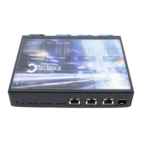
1.1 Functionality and Features of the MediaGateway Figure 1-1: MediaGateway The Technica Engineering MediaGateway allows users to connect and loop through up to 12 100BASE-T1-based devices on the physical layer and to establish virtual point- to-point connections, thus enabling filter and control of data streams (routing, mirroring, forwarding). - Page 6 -40°Celsius to +80°Celsius StartUp Time The StartUp time is valid for HW-Variants 2.1a and higher, and Software 3.7 and higher. If there is information needed about older variants of the MediaGateway, please contact support@technica-engineering.de. PowerUp and Processor Boot Time: 65 ms...
-
Page 7: Warranty And Safety Information
1.2 Warranty and Safety Information Before operating the device, read this manual thoroughly and retain it for your reference. The latest documentation for the MediaGateway can be downloaded here: https://technica-engineering.de/produkt/media-gateway/ Use the device only as described in this manual. Use only in dry conditions. -
Page 8: Declaration Of Conformity
1.3 Declaration of Conformity Figure 1-2: Declaration of conformity MEDIAGATEWAY User Manual... -
Page 9: Scope Of Delivery
1x 1m Ethernet Cable o 1x Black MQS Connector o 3x Blue MQS Connectors o 100BASE-T1 cabling o MQS Crimps o Power cabling o 4mm Banana-plugs Additional cable-sets can be ordered. Please write us at order@technica- engineering.de. MEDIAGATEWAY User Manual... -
Page 10: Hardware Interfaces
2 HARDWARE INTERFACES 2.1 Connectors On the label on top of the device you can see an overview about all HW interfaces of the MediaGateway: Figure 2-1: Label of MediaGateway with pinning information MEDIAGATEWAY User Manual... -
Page 11: Power Connector - Black Mqs Connector
FlexRay option. further Information please contact technicalsales@technica-engineering.de The power supply for the device is supplied by Pin 1 (12Volt) and Pin 2 (Ground). Requirements for the MediaGateway itself: 12 Volts DC up to 1 Ampere (typical 600mA) MEDIAGATEWAY User Manual... -
Page 12: Switch Connectors - Blue Mqs Connectors
The pins marked with (+) or (-) are 12 Volts power output pins. The actual voltage level of these pins depends on the supply voltage of the ECU. Be aware that the sum of all MEDIAGATEWAY User Manual... -
Page 13: Ethernet Connectors
2.1.5 Micro HDMI connector This is an interface for programming and debugging (only for development.) 2.2 Other Interfaces 2.2.1 Status LEDs The MediaGateway has several status LEDs at the front side of the case. Figure 2-3: LEDs MEDIAGATEWAY User Manual... -
Page 14: Push Button (Reset To Default)
If the device is blocked and all LEDs are lit, device must be sent to Technica Engineering. In order to avoid controversues here please make sure that the HOST LED is blinking its normal operation mode and the power supply is stable before the reset. MEDIAGATEWAY User Manual... -
Page 15: Configuration Of Device
PC. 1. Please go to the network adapter settings of your PC and adjust the IP in the same range of your MediaGateway. Default-IP address of the MediaGateway is 192.168.0.49, the subnet mask is 255.255.255.0. 2. Enter the IP address of the MediaGateway in your browser. -
Page 16: System Information Tab
If you want to use multiple devices in one network, you must configure a unique IP address for each device here. Note: If you forgot the IP address of your device you can reset it to default as described 2.2.2 HAPTER MEDIAGATEWAY User Manual... -
Page 17: Control Panel Tab
Software reset. Configuration will NOT be lost. Configuration: It shows the current configuration name. Export: Save the stored configuration from MediaGateway into user’s PC. Import: User can import or export the configuration settings of the device to a file (*.cfg) on a computer connected to the RJ45 Port. -
Page 18: Mediagateway Feature Activation
Ordered Feature Figure 3-5: UUID of MediaGateway Technica Engineering will provide an activation code for the feature. The received activation code must be entered in the Control Panel. The next picture shows how to unlock CAN Gateway feature after receiving the activation code: MEDIAGATEWAY User Manual... - Page 19 Now there is an extra tabulator for the extra feature available: Figure 3-7: CAN Gateway tabulator Remove extra features: With this function all extra features will be removed from this MediaGateway. If this is done, reactivation is possible with the Activation key again. MEDIAGATEWAY User Manual...
-
Page 20: Switch Status Tab
3.5 Switch Status tab Figure 3-8: Switch Status tab The main configuration of the MediaGateway is done in the “Switch Status“tab. Here you can configure details about each port and get some status information about the ports and switch states. -
Page 21: Arl Table Status
Dynamic: the switch is learning the ARL table by itself Static: the ARL table can be set and all entries must be defined by the user. Even the micro of the MediaGateway itself and the PC for configuration. Address Resolution Table... -
Page 22: Dynamic Arl Table
1 = Entry has been learned or accessed since last aging process Age bit 0 = Entry has not been accessed since last aging process Static bit Entry has not been learned and cannot expire Table 3-1: Description of ARL Tabel Entry MEDIAGATEWAY User Manual... -
Page 23: Static Arl Table
That means, if you want to add an entry to current entries, don’t forget to add even the current entries by Figure 3-11: How to add current entries pressing “+”. Please see 3-11 IGURE MEDIAGATEWAY User Manual... - Page 24 Export: the current configuration of the ARL table is exported to a *.json-file. Choose File: the user can import a ARL-table-configuration file of type *.json. After the import the changes must be applied by the button “Apply” and then must be saved by the button “Save configuration”. MEDIAGATEWAY User Manual...
- Page 25 After pressing the save button, the shown tabulator jumps to System Information tab and there is no restart of the MediaGateway. Please go to the Control Panel-tab and do here the saving again. This way the MediaGateway should restart and all changes will be saved.
- Page 26 After pressing the save button, the shown tabulator jumps to System Information tab and there is no restart of the MediaGateway. Please go to the Control Panel-tab and do here the saving again. This way the MediaGateway should restart and all changes will be saved.
-
Page 27: Ports Overview
IEEE 802.1q (VLAN) mode is not hooked (see 3.5.1) HAPTER In this mode, basic configuration details can be adjusted, but the MediaGateway works as standard switch. Grey fields are not configurable and have standard values or no values. MEDIAGATEWAY User Manual... -
Page 28: Ethernet Port Rj-45
This port is monitored: If on this port is incoming traffic, the MediaGateway doesn’t go asleep. This port is not monitored: The MediaGateway can go asleep, even if there is incoming traffic on this port. Mirroring: On each switch only on port can be a mirroring port. Please select the ports to be mirrored. - Page 29 Capable” autonegotiation is done. By the other settings, the speed is set, but master/slave is still autonegotiated. Detected Speed: Here the detected speed is displayed, which is autonegotiated between MediaGateway and connected device on this port. Drop ingress packets with…: Source IP: one IP address can be configured here.
-
Page 30: Sfp Module Port
This port is monitored: If on this port is incoming traffic, the MediaGateway doesn’t fall asleep. This port is not monitored: The MediaGateway can fall asleep, even if there is incoming traffic on this port. Mirroring: On each switch only on port can be a mirroring port. Please select the ports to be mirrored. - Page 31 MAC addresses can be configured. It is a filter outgoing traffic. Data with configured MAC address as destination MAC address will be dropped and forwarded Note: This drop feature is only available if mirroring on this port is activated MEDIAGATEWAY User Manual...
-
Page 32: S1-P4 (Cpu) And Internal Ports (P4 And P8)
This port is monitored: If on this port is incoming traffic, the MediaGateway doesn’t fall asleep. This port is not monitored: The MediaGateway can fall asleep, even if there is incoming traffic on this port. Mirroring: Here you can choose the incoming traffic from the ports, which you want to be mirrored to this port. -
Page 33: 100Base-T1 Ports
Data with configured MAC address as destination MAC address will be dropped and forwarded Note: This drop feature is only available if mirroring on this port is activated 3.6.1.4 100BASE-T1 Ports Figure 3-19: 100BASE-T1 Ports MEDIAGATEWAY User Manual... - Page 34 This port is monitored: If on this port is incoming traffic, the MediaGateway doesn’t fall asleep. This port is not monitored: The MediaGateway can fall asleep, even if there is incoming traffic on this port. Enable port: port is active.
-
Page 35: Port Information While Single Vlan Tagging Is Active
3.5.1) but not double tagging, HAPTER port based single VLAN is activated. In this mode, the routing through the MediaGateway is defined by the configuration of each port. Grey fields are not configurable and have standard values or no values. -
Page 36: Ethernet Port Rj-45
Prevent Sleep Port: This option is available if the function “Prevent sleep” on “Control panel” tab is deactivated. MEDIAGATEWAY User Manual... - Page 37 This port is monitored: If there is incoming traffic on this port, the MediaGateway doesn’t fall asleep. This port is not monitored: The MediaGateway can fall asleep, even if there is incoming traffic on this port. Mirroring: On each switch only on port can be a mirroring port. Please select the ports to be mirrored.
-
Page 38: Sfp Module Port
0x1 and 0xFFF can be defined separated by “,” [E.g.: 100, 101, EDF, …]. Outgoing (allowed) traffic is sent with no VLAN- tag anymore. octets: decimal value of sent octets on this port. octets: decimal value of received octets on this port. MEDIAGATEWAY User Manual... - Page 39 This port is monitored: If there is incoming traffic on this port, the MediaGateway doesn’t fall asleep. This port is not monitored: The MediaGateway can go asleep, even if there is incoming traffic on this port. Mirroring: On each switch only on port can be a mirroring port. Please select the ports...
-
Page 40: S1-P4 (Cpu) And Internal Ports (P4 And P8)
0x1 and 0xFFF can be defined separated by “,” [E.g.: 100, 101, EDF, …]. Outgoing traffic is allowed to leave the switch on this port, if the data is tagged with one of the defined VLAN-IDs. MEDIAGATEWAY User Manual... - Page 41 This port is monitored: If there is incoming traffic on this port, the MediaGateway doesn’t fall asleep. This port is not monitored: The MediaGateway can fall asleep, even if there is incoming traffic on this port. Mirroring: On each switch only on port can be a mirroring port. Please select the ports...
-
Page 42: 100Base-T1 Ports
0x1 and 0xFFF can be defined separated by “,” [E.g.: 100, 101, EDF, …]. Outgoing (allowed) traffic is sent with no VLAN- tag anymore. octets: decimal value of sent octets on this port. octets: decimal value of received octets on this port. MEDIAGATEWAY User Manual... - Page 43 This port is monitored: If there is incoming traffic on this port, the MediaGateway doesn’t fall asleep. This port is not monitored: The MediaGateway can fall asleep, even if there is incoming traffic on this port. Enable port: port is active.
-
Page 44: Port Information While Double Vlan Tagging Is Active
IEEE 802.1q (VLAN) mode is hooked (see 3.5.1) and double tagging is HAPTER hooked, too. In this mode, the routing through the MediaGateway is defined by the configuration of each port. Grey fields are not configurable and have standard values or no values. -
Page 45: Ethernet Port Rj-45
VLAN if received with VLAN on another port o leave without VLAN if received without VLAN on another port Remove: a frame leaves the switch on this port without the VLAN Normalized: a frame leaves the switch on this port with the VLAN MEDIAGATEWAY User Manual... - Page 46 This port is monitored: If there is incoming traffic on this port, the MediaGateway doesn’t fall asleep. This port is not monitored: The MediaGateway can fall asleep, even if there is incoming traffic on this port. Mirroring: On each switch only on port can be a mirroring port. Please select the ports...
-
Page 47: Sfp Module Port
0x1 and 0xFFF can be defined here separated by “,” [E.g.: 100, 101, EDF, …]. Outgoing traffic can leave the switch on this port, if the data is tagged with one of the defined VLAN-IDs. Only outerVLANs are checked! MEDIAGATEWAY User Manual... - Page 48 This port is monitored: If there is incoming traffic on this port, the MediaGateway doesn’t fall asleep. This port is not monitored: The MediaGateway can fall asleep, even if there is incoming traffic on this port. Mirroring: On each switch only on port can be a mirroring port. Please select the ports...
- Page 49 MAC addresses can be configured. It is a filter outgoing traffic. Data with configured MAC address as destination MAC address will be dropped and forwarded Note: This drop feature is only available if mirroring on this port is activated MEDIAGATEWAY User Manual...
-
Page 50: S1-P4 (Cpu) And Internal Ports (P4 And P8)
“as received” => o leave with VLAN if received with VLAN on another port o leave without VLAN if received without VLAN on another port Remove: a frame leaves the switch on this port without the VLAN MEDIAGATEWAY User Manual... - Page 51 This port is monitored: If there is incoming traffic on this port, the MediaGateway doesn’t fall asleep. This port is not monitored: The MediaGateway can fall asleep, even if there is incoming traffic on this port. Mirroring: On each switch only on port can be a mirroring port. Please select the ports to be mirrored.
-
Page 52: 100Base-T1 Ports
“as received” => o leave with VLAN if received with VLAN on another port o leave without VLAN if received without VLAN on another port Remove: a frame leaves the switch on this port without the VLAN MEDIAGATEWAY User Manual... - Page 53 This port is monitored: If there is incoming traffic on this port, the MediaGateway doesn’t fall asleep. This port is not monitored: The MediaGateway can fall asleep, even if there is incoming traffic on this port. Enable port: port is active.
-
Page 54: Important Vlan Tagging Rules
VLAN ID on this specific port. The MediaGateway does never overwrite any VLAN tags. It means a frame already tagged before entering a switch of the MediaGateway’s switch doesn’t change its VLAN tag. Both rules are valid for both VLAN tags and in both VLAN tagging modes (single/double). -
Page 55: Can Gateway
Note: The CAN Gateway is in the Microcontroller (CPU). The Switch 1 has to be configured in a way that the microcontroller has still a connection to your PC. Note: The CAN Gateway is not able to work with CAN-FD. MEDIAGATEWAY User Manual... - Page 56 Communication mode in basic settings is not selectable. Please change into advanced settings for changing the communication mode. After choosing the communication mode please change back to the Basic settings. MEDIAGATEWAY User Manual...
-
Page 57: Communication Mode: Udp
Figure 3-29: Overview CAN Gateway settings in UDP-mode CAN Parameters: (only in advanced mode available) Speed: For each CAN channel the correct speed must be selected (CAN- FD is not available.) Following kilo baud per second are available: 125Kbps 500Kbps 1000Kbps MEDIAGATEWAY User Manual... - Page 58 CAN channel. This is necessary if there is no other communication partner for the CAN messages. Ethernet to CAN: Incoming configurable parameters: rxPort: The MediaGateway will wait for UDP-CAN packets on selected UPD port. Please select a non-reserved port number. CAN to Ethernet: Outgoing configurable parameters:...
-
Page 59: Communication Mode: Raw
Figure 3-32: Overview CAN Gateway settings in RAW mode CAN Parameters: (only in advanced mode available) Speed: For each CAN channel the correct speed must be selected (CAN- FD is not available.) Following kilo baud per second are available: 125Kbps 500Kbps 1000Kbps MEDIAGATEWAY User Manual... - Page 60 CAN channel. Listen-Only means no acknowledge is done for CAN messages on this bus by the MediaGateway. In deactivated Listen-Only Mode, the MediaGateway acknowledges every message on the CAN channel. This is necessary if there is no other communication partner for the CAN messages.
-
Page 61: Communication Mode: Speed Raw
If the target MAC address or the EtherType has the default value set, the Ethernet CAN Gateway will be disabled. Here you can see an overview about the configuration board for the Speed RAW mode. Figure 3-35: Overview CAN Gateway settings in Speed RAW mode MEDIAGATEWAY User Manual... - Page 62 CAN channel. Listen-Only means no acknowledge is done for CAN messages on this bus by the MediaGateway. In deactivated Listen-Only Mode, the MediaGateway acknowledges every message on the CAN channel. This is necessary if there is no other communication partner for the CAN messages.
-
Page 63: Communication Mode: Extreme Raw
If the target MAC address or the EtherType has the default value set, the Ethernet CAN Gateway will be disabled. Here you can see an overview about the configuration board for the Extreme RAW mode. MEDIAGATEWAY User Manual... - Page 64 Filtering: Please select the CAN channels by checking the box. Then you can adjust CAN ID Filtering. For each selected CAN channel there appears a line where the CAN IDs must be put in. Values are in hexadecimal and are separated by a comma. MEDIAGATEWAY User Manual...
- Page 65 CAN channel. Listen-Only means no acknowledge is done for CAN messages on this bus by the MediaGateway. In deactivated Listen-Only Mode, the MediaGateway acknowledges every message on the CAN channel. This is necessary if there is no other communication partner for the CAN messages.
-
Page 66: Difference Between All Raw Modes
The CAN packet is the payload of the UDP frame or RAW ethernet frame. The following tables show the structure of this payload: 8 Byte Frame Version ID type Channel type Table 3-4: Payload of CAN/Ethernet Packet MEDIAGATEWAY User Manual... - Page 67 Frame type UINT8 0 for CAN data frame 1 for CAN remote transmission request UINT8 Payload length of the CAN packet D0 to D7 up to UINT64 Payload Table 3-5: Detailed Information about Payload of CAN/Ethernet Packet MEDIAGATEWAY User Manual...
-
Page 68: Configuration Examples
Note: It makes sense to configure the configuration port first. The connection between a PC and the MediaGateway for access to the webserver on the microcontroller is the same as any other connection through the MediaGateway. => S1-P4 to PC-port must be configured. - Page 69 S1-P4 can leave on this port the Switch_1 do the same for the other direction with e.g. 0xDD as VLAN-ID: do a save if you have still access the S1-P5 is as configuration-port defined MEDIAGATEWAY User Manual...
- Page 70 A VLAN membership is not necessary because of the mirroring. InnerVLAN IDs are not touched by this configuration. It doesn’t matter if the original data has singleVLAN tags or not (egress VID remarking is “As received”) Do a save MEDIAGATEWAY User Manual...
-
Page 71: Get Access By Third Communication Partner
“Inject”-Port (S3-P8) to the DUT_2. Figure 4-2: Example for inject Steps to configure your MediaGateway: Take your MediaGateway and configure it like the example before (4.1). Go to port S3-P8 default VLAN ID e.g. 0x38 and set the VLAN membership... - Page 72 P2 to S3-P8 without touching the outerVLAN tag => set VLAN membership 0x12 and set Egress VID remarking for outerVLAN tags to Normalized. Do a save Now you have access on the “Inject”-Port by any other device to the DUT_2 in our example. MEDIAGATEWAY User Manual...
-
Page 73: Ptp And 802.1As In The Mediagateway
5 PTP AND 802.1AS in the MediaGateway This chapter explains the current support of the MediaGateway for 802.1AS protocol. 802.1AS is a protocol used between two or more devices to synchronize all of them through an Ethernet communication. This synchronization allows two or more devices... - Page 74 “correction field” will be changed and this parameter will be used on reception side to adjust the reference time of the system considering the delay of the switch and the delay in the path „Time-aware system i-1“ to „Time-aware system i“. MEDIAGATEWAY User Manual...
-
Page 75: Propagation Delay Measurement
For the correction adjust of the time reference transmitted by the Sync and Follow Up Packets, the delay between the initiator of the protocol „Time-aware system i-1“ and the first slave port of the MediaGateway „Time-aware system i“, should be measured. ( ��... -
Page 76: 802.1As In The Mediagateway
The implementation allows only the use of the 802.1AS in the 12 x OABR Ports of the MediaGateway. Due to technical reasons, the use of the 802.1AS protocol is not possible in Ethernet ports. -
Page 77: Diagnostic Frames
6 Diagnostic Frames There are two diagnostic frames implemented in the MediaGateway. To see them, please activate Diagnose-Service (C 3.4.1) and mirror the Port S1-P4 (CPU). HAPTER Both frames are based on SOME/IP. For specific information about SOME/IP please SOME/IP P... - Page 78 (Nr_port x 21) + 30 Port Name (Nr_port x 21) + 31 to (Nr_port x 21) + 32 Defined Default VLAN ID (Nr_port x 21) + 33 Inner VID Remarking (Nr_port x 21) + 34 Outer VID Remarking MEDIAGATEWAY User Manual...
-
Page 79: Port Information Frame (0X8002)
This frame contains the information of 15 ports (12 BR ports and the 3 Ethernet Ports). The same information for each port is available. The related bytes for each port are indicated in the payload by the variable “Nr_Port” (0 to 14). MEDIAGATEWAY User Manual... - Page 80 (Nr_port x 22) + 37 to (Nr_port x 22) + 38 Nr_disconnections (Nr_port x 22) + 39 to (Nr_port x 22) + 40 Last disconnection time in [ms] (Nr_port x 42) + 41 Separator Byte Table 6-3: Specific information of bytes MEDIAGATEWAY User Manual...
-
Page 81: Mediagateway Remote Control
MediaGateway through SOME/IP messages. For specific information about SOME/IP please see SOME/IP P AUTOSAR ROTOCOL PECIFICATION These messages have to be sent to the MediaGateway with the destination IP of MediaGateway and UDP port 30491 Currently, the following methods are implemented: restart device import configuration export configuration... -
Page 82: Reset Device
This method has the same behaviour as the Import button from webpage of the MediaGateway. This method stores a configuration into the flash. The new configuration is the payload. Note: New settings will be applied when next device restart is performed. -
Page 83: Export Configuration
7.3 Export Configuration This method has the same behaviour as the Export button from webpage of the MediaGateway. The response message from MediaGateway contains the *.cfg file in its payload as HEX stream. Request with: Method ID: 0x0003 Length: 0x8... -
Page 84: Set Wakeup Line Status
0x02: for Dynamic Operation 7.6 Set WakeUp Line Status This method provides the user the possibility of driving the wakeup line to high or low level. Two wake up lines are available in the MediaGateway. Request with: Method ID: 0x0006... -
Page 85: Set Port Enabled/Disabled (Only 100Base-T1-Ports)
Via this method the user can enable or disable 100BASE-T1 ports, similarly to the Enable port function on the webserver for the 100BASE-T1 ports. Request with: Method ID: 0x0008 Length: 0xA Payload: 2 bytes contain the information, which port is enabled/disabled 2 Byte 100BASE-T1 Port selection Enable/disable MEDIAGATEWAY User Manual... -
Page 86: Set Port To Master/Slave (Only 100Base-T1-Ports)
Via this method the user can set 100BASE-T1 ports to master or slave,similarly to the BroadR-Reach® mode function on the webserver for the 100BASE-T1 ports. Request with: Method ID: 0x0009 Length: 0xA Payload: 2 bytes contain the information, which port is set to master/slave. 2 Byte 100BASE-T1 Port selection BroadR-Reach® mode MEDIAGATEWAY User Manual... -
Page 87: Reset To Default
This method returns a SOME/IP message with return code 0x00 (OK) before restart. 7.11 Get System Information This method returns information about MediaGateway and its active licenses. It is the same information, that is shown on System Information tab on the Webserver of the MediaGateway. Request with: Method ID: 0x0011... - Page 88 HW version low UINT8 e.g. 0x06 for HW v2.6 SW version UINT24 e.g. 0x040400 for SW v4.4.0 BMW extra function UINT8 0x00 disabled 0x01 enabled/unlocked CAN Gateway UINT8 0x00 disabled 0x01 enabled/unlocked FlexRay UINT8 0x00 disabled 0x01 enabled/unlocked MEDIAGATEWAY User Manual...
-
Page 89: Application And Firmware Update
8 APPLICATION AND FIRMWARE UPDATE You can download the latest firmware and documentation for the MediaGateway here: https://technica-engineering.de/produkt/media-gateway/ 8.1 Preconditions and important information Warnings: Please do not downgrade the bootloader or application to a former version. Please follow this update instruction to avoid erroneous states of the device. -
Page 90: Troubleshooting And Faq
=> Switch 3 is damaged, switch 2 and 1 are still working. If the first switch (Switch 1) is damaged, the MediaGateway is not working anymore. If there is still warranty, please send it back to Technica Engineering GmbH and we will provide you with a new one. -
Page 91: Problems With Website Interface
Currently Audio Video Bridging is not supported. Only automotive 802.1AS time synchronization protocol is implemented (PTP). 9.8 Maximum Frame Size The maximum frame size for all ports is 2000 bytes. Tagged and untagged frames will be dropped if the frame length is larger than 2000 bytes. MEDIAGATEWAY User Manual... -
Page 92: List Of Figures
10 LIST OF FIGURES Figure 1-1: MediaGateway ....................5 Figure 1-2: Declaration of conformity ................8 Figure 2-1: Label of MediaGateway with pinning information ........10 Figure 2-2: Pinning of blue MQS connectors ..............12 Figure 2-3: LEDs ........................ 13 Figure 3-1: Home Screen MediaGateway ............... - Page 93 Figure 4-2: Example for inject ..................71 Figure 5-1: Sync and Follow_Up messages ..............74 Figure 5-2: p_delay messages and formula ..............75 Figure 6-1: Board Configuration Frame ................77 Figure 6-2: Board Information Frame ................79 MEDIAGATEWAY User Manual...
-
Page 94: Changelog
11 CHANGELOG Version Chapter Description Date Added ARL status 03.2018 MediaGateway Remote control revised Added SFP port information and new SFP Modules 4.98 compatibility CANGateway Chapter updated Removed bootloader update chapter Complete rework of all Chapters 03.2020 MEDIAGATEWAY User Manual... -
Page 95: Contact
If you have any questions regarding this product, feel free to contact us: Technica Engineering GmbH Leopoldstraße 236 D - 80807 München Tel.: +49 89 200 07 24-44 Fax: +49 89 200 07 24-30 E-Mail: support@technica-engineering.de Web: www.technica-engineering.de MEDIAGATEWAY User Manual...
Need help?
Do you have a question about the MediaGateway and is the answer not in the manual?
Questions and answers