Table of Contents
Advertisement
GENERAL DESCRIPTION
The MC3635 is an ultra-low power, low-
noise, integrated digital output 3-axis
accelerometer with a feature set optimized
for wearables and consumer product
motion sensing. Applications include
wearable consumer products, IoT devices,
user interface control, gaming motion input,
electronic compass tilt compensation for
cell phones, game controllers, remote
controls and portable media products.
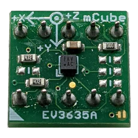
The EV3635B is a prebuilt circuit board with
MC3635 3-axes sensor. The MC3635 has
internal sample rate from 14 to 1300
samples / second and measures
acceleration with a wide usage range, from
+/-2g up to +/-16g, and 6-bit to 14-bit high
precision ADC output, which is easy to fit
on top of the microcontroller, such as an
Arduino. The accelerometer communicates
via I2C/SPI and gives out motion detection
or sample acquisition conditions to trigger
an interrupt toward an MCU.
The sensor data is easily readable by
connecting DVDD to 3.3V, GND to ground,
and SCL/SDA pins to your Arduino I2C
clock and data pin respectively. Download
the MC3635 library from GitHub onto the
board, run the example sketch, and then
sensor data shortly comes out in raw data
count and SI unit accelerometer
measurements. An easy-to-use
demonstration on EV3635B using the
Arduino platform is included in this
document.
mCube Proprietary.
© 2020 mCube Inc. All rights reserved.
The MC3635 Evaluation Board
APS-045-0018v1.2
Quick Start Guide and Demo
MC3635 FEATURES
Range, Sampling & Power
•
±2, 4, 8, 12 or 16g ranges
•
8, 10 or 12-bit resolution with FIFO
o
14-bit single samples
•
Sample rate 14 - 1300 samples/sec
•
Sample trigger via internal
oscillator, clock pin or software
command
•
Sniff and Wake modes
•
0.4 μA Sniff current @ 6Hz
•
Separate or combined sniff/wake
•
Ultra-Low Power with 32 sample
FIFO
0.9 μA typical current @ 25Hz
o
1.6 μA typical current @ 50Hz
o
2.8 μA typical current @ 100Hz
o
36 μA typical current @ 1300Hz
o
Simple System Integration
•
I2C interface, up to 1 MHz
•
SPI Interface, up to 8 MHz
•
1.6 × 1.6 × 0.94 mm 10-pin
package
•
Single-chip 3D silicon MEMS
•
Low noise to 2.3mgRMS
1 / 20
Advertisement
Table of Contents

Related Manuals for Mcube MC3635

Summary of Contents for Mcube MC3635
- Page 1 The MC3635 Evaluation Board Quick Start Guide and Demo GENERAL DESCRIPTION MC3635 FEATURES The MC3635 is an ultra-low power, low- Range, Sampling & Power noise, integrated digital output 3-axis • ±2, 4, 8, 12 or 16g ranges accelerometer with a feature set optimized •...
-
Page 2: Table Of Contents
Config Interrupt Mode ......................14 4.13 Read Raw Count Data ....................... 14 Downloads ........................15 MC3635 Accelerometer Datasheet and Quick Start Guide ..........15 MC36XX Driver at GitHub ....................15 All Other mCube Documentation ..................15 Schematics ........................16 mCube Proprietary. - Page 3 The MC3635 Evaluation Board Quick Start Guide and Demo Bill of Materials ......................17 Fabrication Print ......................18 Revision History ......................19 Legal ..........................20 mCube Proprietary. APS-045-0018v1.2 3 / 20 © 2020 mCube Inc. All rights reserved.
-
Page 4: General Operation
By default, Arduino UNO operates at 5V, which is higher than the maximum voltage rating for the evaluation board. Please refer to an excellent tutorial on modifying Arduino UNO to output at 3.3V: https://learn.adafruit.com/arduino-tips-tricks-and-techniques/3-3v-conversion mCube Proprietary. APS-045-0018v1.2 4 / 20 © 2020 mCube Inc. All rights reserved. -
Page 5: I2C Pins
4.7K ohm resistors to the SDA and SCL pin respectively. It will work the same either way. NOTE: DO NOT install more than one setup pull-up resistors per I2C bus. mCube Proprietary. APS-045-0018v1.2 5 / 20 © 2020 mCube Inc. All rights reserved. -
Page 6: Spi Pins
I2C commands toward related registers). R6: If using the sensor interrupt signal as open-drain, then install pull-up resistor ~4.7KΩ into R6 (not installed by default). mCube Proprietary. APS-045-0018v1.2 6 / 20 © 2020 mCube Inc. All rights reserved. -
Page 7: Assembly And Test
Connect the SCL pin to the I2C clock SCL pin on your Arduino. • Connect the SDA pin to the I2C data SDA pin on your Arduino. The MC3635 has a default I2C address of 0x4C and it can be changed to 0x6C by tying the SDO pin to VDD. mCube Proprietary. -
Page 8: Spi Interface
Connect SDO to ICSP-1 as Master Input, Slave Output. • Connect SDA to ICSP-4 as Master Output, Slave Input. • Connect SCS to digital I/O pin 10 as Slave Chip Select. mCube Proprietary. APS-045-0018v1.2 8 / 20 © 2020 mCube Inc. All rights reserved. -
Page 9: Demo
3 DEMO 3.1 DOWNLOAD THE DRIVER FROM GITHUB To begin reading sensor data, you will need to download the MC3635 Library from the GitHub repository. You can do that by visiting the GitHub repository and manually downloading or simply click this button the attached URL to download the zip file. -
Page 10: Load The Demo
Open up File->Examples-> MC36XX -> MC36XX_demo and upload to your Arduino wired up to the sensor Now open the serial terminal window at 115,200 baud rate speed to begin the test. mCube Proprietary. APS-045-0018v1.2 10 / 20 © 2020 mCube Inc. All rights reserved. - Page 11 Default input pin for interrupt is pin 8 and default FIFO threshold is 3 samples. FIFO size could be set to maximum 32 samples or just enable FIFO to FIFO_FULL mode. #define INTERRUPT_PIN #define FIFO_SIZE mCube Proprietary. APS-045-0018v1.2 11 / 20 © 2020 mCube Inc. All rights reserved.
-
Page 12: Library Reference
MC36XX_acc.SetResolutionCtrl(MC36XX_RESOLUTION_14BIT); When the FIFO is enabled, the output of the FIFO is mapped to registers 0x02 to 0x07, and the data has a maximum resolution of 12-bits mCube Proprietary. APS-045-0018v1.2 12 / 20 © 2020 mCube Inc. All rights reserved. -
Page 13: Read Resolution
For each axis, a delta count is generated and compared to the threshold. When the delta count is greater than the threshold, a SNIFF wakeup event occurs. There is a unique sniff mCube Proprietary. APS-045-0018v1.2 13 / 20 © 2020 mCube Inc. All rights reserved. -
Page 14: Config Interrupt Mode
MC36XX have 5 interrupt modes – FIFO_THR | FIFO FULL | FIFO EMPTY | ACQ | WAKE. These modes can only be enabled separately. 4.13 READ RAW COUNT DATA Read the raw count data and SI unit measurement with: MC36XX_acc.readRawAccel(); mCube Proprietary. APS-045-0018v1.2 14 / 20 © 2020 mCube Inc. All rights reserved. -
Page 15: Downloads
MC3635 3-Axis Accelerometer EV3635B Quick Start Guide and Demo 5 DOWNLOADS 5.1 MC3635 ACCELEROMETER DATASHEET AND QUICK START GUIDE https://mcubemems.com/product/mc3635-3-axis-accelerometer/ 5.2 MC36XX DRIVER AT GITHUB https://github.com/mcubemems/mCube_mc36xx_arduino_driver 5.3 ALL OTHER MCUBE DOCUMENTATION https://mcubemems.com/resources-support/resources/ mCube Proprietary. APS-045-0018v1.2 15 / 20 © 2020 mCube Inc. All rights reserved. -
Page 16: Schematics
R7: Sensor’s driving current can be measured by putting an ammeter in place of R7. The physical location of the resistor is in the diagram in Section 1.3. DNI: Do Not Install mCube Proprietary. APS-045-0018v1.2 16 / 20 © 2020 mCube Inc. All rights reserved. -
Page 17: Bill Of Materials
RES-0603 Walsin WR06X102JTL RES-0603 Walsin WR06X103JTL 4.7K RES-0603 Walsin WR06X472JTL 4.7K RES-0603 Walsin WR06X472JTL 4.7K RES-0603 Walsin WR06X472JTL RES-0603 Walsin WR06X000PTL MC3635 LGA10_1.6 x 1.6 mCube MC3635 mCube Proprietary. APS-045-0018v1.2 17 / 20 © 2020 mCube Inc. All rights reserved. -
Page 18: Fabrication Print
MC3635 3-Axis Accelerometer EV3635B Quick Start Guide and Demo 8 FABRICATION PRINT NOTE: All dimensions are in millimeters. mCube Proprietary. APS-045-0018v1.2 18 / 20 © 2020 mCube Inc. All rights reserved. -
Page 19: Revision History
Revised schematics and BOM. 2020-02-05 APS-045-0018v1.2 Revised schematics and BOM. Added warning in section 1.2. Changed illustration to Arduino DUE. Revised section 3 & 4 to illustrate demo program. mCube Proprietary. APS-045-0018v1.2 19 / 20 © 2020 mCube Inc. All rights reserved. -
Page 20: Legal
M-CUBE and the M-CUBE logo are trademarks of M-CUBE, Inc., All other product or service names are the property of their respective owners. © M-CUBE, Inc. 2020. All rights reserved. mCube Proprietary. APS-045-0018v1.2 20 / 20 © 2020 mCube Inc. All rights reserved.
Need help?
Do you have a question about the MC3635 and is the answer not in the manual?
Questions and answers