
Related Manuals for Orolia Spectracom VersaPNT

Summary of Contents for Orolia Spectracom VersaPNT
- Page 1 VersaPNT Getting Started Guide Document Part No.: 1228-5000-0057 Revision: 3.0 Date: 5-August-2019...
- Page 2 This Getting Started Guide is a supplement to the main user manual for VersaPNT. The latest version main user manual found online under manuals.spectracom.com © 2018 Spectracom. An Orolia brand. Orolia USA, Inc. dba Spectracom VersaPNT Getting Started Guide Rev. 3.0...
- Page 3 About this Guide Product Overview 1.1 Interfaces Overview 1.1.1 Input Timing Interfaces 1.1.2 Output Timing Interfaces 1.1.3 Navigation Inputs & Outputs 1.1.4 Other Interfaces 1.2 Connectors and their Pinouts 1.2.1 Power Connector 1.2.2 Input/Output Connector 1.2.3 Ethernet Connector 1.2.4 Optional I/O Connector 1.2.5 Coaxial Connectors 1.3 Included Cables 1.4 Status LEDs...
-
Page 4: Table Of Contents
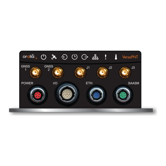
2.4.1 "NMEA Output" Tab 2.4.2 "Calibration" Tab/Antenna Installation 2.4.3 "Log" Tab 2.4.4 "FIR Filter" Tab 2.4.5 "Coning/Sculling" Tab 2.4.6 "Frame Rotation" Tab 2.5 INS Initialization 2.6 INS Expert Mode 2.7 VICTORY Configuration SAFETY 3.1 SAFETY: Before You Begin Installation 3.2 Regulatory Compliance Technical Support 4.1 Regional Contact VersaPNT Getting Started Guide •... - Page 5 1.1 Interfaces Overview Product Overview This section is designed to help you become familiar with the structure, features, and func- tions of the VersaPNT. Interfaces Overview All of VersaPNT's interfaces are integrated into the unit's connectors, which are located on the front panel: Figure 1-1: VersaPNT front panel connectors...
- Page 6 1.1 Interfaces Overview 1.1.1 Input Timing Interfaces Table 1-1: VersaPNT timing inputs (default setup) Connector No. DCLS Total INPUT SIGNAL (see Fig. available TTL 10V above) 1PPS ASCII/HaveQuick/IRIG B ASCII/NMEA Network Interface (10/100/1000bT): NTP (Stratum 2), PTP Multi I/O interfaces (connector no. 4) are software-configurable, see "Assigning I/O Pins"...
- Page 7 1.1 Interfaces Overview Table 1-3: Navigation input and output options DCLS Option Number/ RS-422 Connector No. SIGNAL TYPE RS- 232 Channel Position (n or p) (see Fig. above) NMEA OUT Channel 4 PPS IN Option & Channel 1 PPS OUT Option &...
- Page 8 1.2 Connectors and their Pinouts Connectors and their Pinouts All of VersaPNT's connectors are provided at the front panel of the unit, below the Status LEDs. 1.2.1 Power Connector Note: View in mating direction from front. Table 1-4: Power connector pinout Signal (10 to 32 V) Main...
- Page 9 1.2 Connectors and their Pinouts Test any new cables to safely power the unit before connecting your VersaPNT to any other inputs or outputs (such as a GNSS antenna), and before grounding your unit to a vehicle. 1.2.2 Input/Output Connector VersaPNT has a 26- pin input/output connector that offers 8 software- configurable CHANNELS, plus one fixed DCLS channel, and a USB interface.
- Page 10 1.2 Connectors and their Pinouts 1.2.3 Ethernet Connector Note: View in mating direction from front. The Ethernet connector provides two 1GbE network connections, using 8 wires (pinout below). Table 1-6: Ethernet connector pinout Signal Signal Ethernet_1 A+ Ethernet_2 A+ Ethernet_1 A– Ethernet_2 A–...
- Page 11 1.2 Connectors and their Pinouts 1.2.5 Coaxial Connectors VersaPNT offers five (5) coaxial connectors, three (3) of which can be configured at the factory to accommodate requirements for e.g., IRIG AM signals or additional 10 MHz out- puts. The minimum configuration includes the GNSS antenna and a 10 MHz sinewave...
- Page 12 1.3 Included Cables Included Cables The VersaPNT Evaluation Kit contains the following cables (antenna cable not shown): Power Cable I/O Cable VersaPNT Getting Started Guide Rev. 3.0...
- Page 13 1.3 Included Cables I/O Breakout Cable Ethernet Data Cable VersaPNT Getting Started Guide Rev. 3.0...
- Page 14 1.4 Status LEDs Status LEDs VersaPNT's front panel status LEDs provide a real-time status overview: Eight (8) LEDs indicate the unit's current operating state: The LEDs can be disabled, see "Blackout Mode" on page 12. 1.4.1 Blinking Intervals The status LEDs can communicate five different operating states: "OFF"...
- Page 15 1.4 Status LEDs Table 1-7: Common light patterns Start-up HEARTB. Acquir- FAST FAST FAST FAST FAST FAST HEARTB. FAST ing fix Soft- FAST FAST FAST HEARTB. ware upgrade 1.4.3 Legend, individual LEDs Table 1-8: Legend for Status LEDs Icon Light Meaning No power HEARTBEAT...
- Page 16 1.5 The VersaPNT Web UI Icon Light Meaning No network detected FAST Network malfunction detected (e.g., no auto-negotiation) Network OK, configuration OK Unit OK FAST Unit requires attention; check other status LEDs, see Web UI "LED Lighting Patterns" on page 10 HEARTBEAT See table Temperature OK...
- Page 17 1.5 The VersaPNT Web UI 1.5.1 The Web UI HOME Screen HOME screen of the VersaPNT web user interface ("Web UI") provides com- prehensive status information at a glance, including: vital system information current status of the references key performance/accuracy data major events.
- Page 18 1.5 The VersaPNT Web UI BLANK PAGE. VersaPNT Getting Started Guide Rev. 3.0...
- Page 19 Quick Start During the procedure described below, you will connect the Power cable, the Multi I/O cable, and the Ethernet cable to the unit. These cables are included in the Evaluation kit. If you plan to use your own cables, some of these instructions may not apply. The step-by-step instructions below outline the VersaPNT installation and configuration process: Install VersaPNT...
- Page 20 USB: Connect the Multi I/O connector to the VersaPNT unit. If you are using the Evaluation Kit, connect the Multi I/O USB output to a PC. Install a ter- ® ® minal emulator program on the PC (e.g., TeraTerm or PuTTY Ethernet: Connect the Ethernet cable to the ETH port of the unit.
- Page 21 2.1 Network Setup Network Setup After making the connections outlined in the Quick Start list, the following information will help you to establish a network connection. VersaPNT has a Command Line Interpreter ("CLI"). The CLI is available either through the USB serial or Ethernet direct VersaPNT-to-PC connections. web user interface ("Web UI") is used to configure and monitor the unit.
- Page 22 2.1 Network Setup Access the CLI via ssh or telnet: The required port configuration is 115200 8N1: Press the Return key, and enter the login credentials: Note: The default login credentials are: User name = spadmin Password = admin123 (will not be displayed on the screen) VersaPNT Getting Started Guide Rev.
- Page 23 2.1 Network Setup Note: For your reference, the command helpcli produces a list of available commands. Press the space key to display the next page, or the key to display the previous page. Note: Should it become necessary to leave the command help mode (indicated by a command line prompt ":"), press Q, or Ctrl b.
- Page 24 2.1 Network Setup c. Login to the VersaPNT Web UI, using the same credentials as mentioned above. d. If so required, you can also change VersaPNT's IP configuration (address, sub- net, gateway, ...): i. Navigate to MANAGEMENT > Network Setup. ii.
- Page 25 2.2 Zero Configuration Setup Zero Configuration Setup As an alternative to conventional network configuration, VersaPNT can also be set up using the zero-configuration networking technology ("zeroconf"). Note: You can use Zeroconf on either Ethernet port if DHCP is enabled. Zeroconf must be used with a DHCP server. When using zeroconf, a TCP/IP network will be created automatically, i.e.
- Page 26 2.2 Zero Configuration Setup 2.2.1 Using Zeroconf Connect to the Web UI of your VersaPNT unit in these steps: 1. Check the serial number label on the side of the unit, and write down the last 6 digits of the MAC 0 address: e.g., "0C 00 19".
- Page 27 2.3 Assigning I/O Pins Assigning I/O Pins VersaPNT's I/O connector is software configurable, i.e. the pin interfaces and the signal modulations can be configured by the user via the VersaPNT Web UI. The software-configurable 26-pin I/O connector comprises 9 user-configurable Channels, plus one fixed USB interface.
- Page 28 2.3 Assigning I/O Pins 2.3.1 Signal Types The table below shows the maximum number of available interfaces for each signal type. Note that you can assign only one signal for each pin pair, hence only four to nine input and output signals can be transmitted/received at any given time.
- Page 29 2.3 Assigning I/O Pins Spectracom provides an online interactive I/O switch matrix configurator that can be used to design a custom I/O configuration: http://manuals.spectracom.com/VSS/Content/VSS/SETUP/IOpinConfiguration.h The table below illustrates the signal combinations that can be assigned to the 18 con- figurable pins. Table 2-2: I/O signal mapping to Channels Notes:...
- Page 30 2.3 Assigning I/O Pins 1. In the VersaPNT Web UI, navigate to MANAGEMENT > NETWORK: Pin Layout. Pin Layout screen will be displayed. 2. Prior to assigning the new output, identify a pin pair in the pin Layout table that is not used (Signal = "None") or not needed.
- Page 31 2.3 Assigning I/O Pins DCLS Option Number/ RS-422 SIGNAL TYPE Pins RS- 232 Channel Position (n or p) GPS OUT Option 4 & Channel 4 9 & 10 IMU IN Option 5 & Channel 5 11 & 12 1 (p) IMU IN Option 6 &...
- Page 32 2.3 Assigning I/O Pins Figure 2-2: Default I/O configuration To restore the default I/O pin configuration: A. Navigate to the MANAGEMENT: NETWORK > Pin Layout screen. B. In the Actions panel on the left, click Restore Default Layout. Reloading the Current I/O Configuration To reload the currently used I/O configuration after adding pin layout changes, but before clicking Apply...
- Page 33 2.4 INS Configuration INS Configuration VersaPNT is equipped with a GPS-aided high-performance Inertial Navigation System (INS). This MEMS-based unit incorporates 3-axis accelerometers, gyros, magnetometer (all of which 3-axis), as well as a barometric pressure sensor, a temperature sensor and two sep- arate 50-channel L1 GPS receivers.
-
Page 34: Nmea Output" Tab
2.4 INS Configuration FW Version INS Mode [aligned, aligning, initializing, none]: The INS mode should read "aligned" for accurate navigation. GPS Fix [3D, 2D, no fix, time only]: For accurate positioning, the unit needs a 3D fix (at least 4 satellites). Num Sats: The number of tracked satellites 2. -
Page 35: Calibration" Tab/Antenna Installation
2.4 INS Configuration Header Output Type Recommended Minimum Specific Data True Heading and Status Time & Date In order to output NMEA messages, you must configure both the settings in this NMEA Output tab, AND the pinout configuration of the Multi I/O connector. NMEA Out is only available on Channel 4 (see "Assigning I/O Pins"... - Page 36 2.4 INS Configuration Antenna 2: [checkbox] Select ON when using a second GNSS antenna. Note that the use of a second antenna is optional, but a second antenna is required for com- passing functionality. Also note that the offset of antenna 2 is relative to antenna 1, not to the VersaPNT X-Y-Z etching (see illustration below).
-
Page 37: Log" Tab
2.4 INS Configuration Figure 2-3: GPS antenna offset (Image source: VectorNav Technologies) 2.4.3 "Log" Tab You can configure your unit to stop logging events in this tab or to change the file name that your logs are stored in. Log To CSV File: [checkbox: OFF] Select ON to log to a comma-separated values file. -
Page 38: Coning/Sculling" Tab
2.4 INS Configuration Mag Window Size (default 400 Hz): Define the number of magnetometer samples at the IMU rate which will be averaged for each output measurement. Accel Window Size (default 400 Hz): Define the number of acceleration sensor samples at the IMU rate which will be averaged for each output measurement. Gyro Window Size (default 400 Hz): [Range: ] Define the number of gyroscope... -
Page 39: Frame Rotation" Tab
2.4 INS Configuration To configure the compensation (if set to ON), the INS needs to be operated in Expert Mode. Acceleration Compensation: [checkbox: OFF] This setting selects the compensation to be applied to the acceleration measurements before integration. If set to ON, the Kalman filter’s real-time estimate of the accel biases will be used to compensate the IMU meas- urements before integration. -
Page 40: Ins Initialization
2.5 INS Initialization Note: The matrix C in the Reference Frame Rotation Register must be an orthonormal, right-handed matrix. The sensor will output an error if the tol- erance is not within 1e-5. The sensor will also report an error if any of the parameters are greater than 1 or less than -1. -
Page 41: Ins Expert Mode
2.6 INS Expert Mode Aligned indicates the solution is reliable and GNSS verified Aligning indicates either that the current solution is outside the range of validity, or that the INS is working to develop a solution None indicates that no INS solution is currently available. This message also occurs at startup. -
Page 42: Victory Configuration
2.7 VICTORY Configuration NTP is configured as an input reference, VersaPNT could lose syn- chronization). To access the INS Expert Mode, navigate to MANAGEMENT > Setup. The switch for the INS Expert Mode is in the ACTIONS panel. Caution: Any configurations made in INS Expert Mode will be lost as soon as INS Expert Mode... -
Page 43: Safety
3.1 SAFETY: Before You Begin Installation SAFETY Table 3-1: Safety symbols used on this product or in this document Symbol Signal word Definition Potentially dangerous situation which may lead to per- DANGER! sonal injury or death! Follow the instructions closely. Potential equipment damage or destruction! CAUTION! Follow the instructions closely. -
Page 44: Regulatory Compliance
3.2 Regulatory Compliance Installation of the equipment must comply with local and national electrical codes. DANGER! — DO NOT OPEN EQUIPMENT, UNLESS AUTHORIZED: The interior of this equipment does not have any user serviceable parts. Contact Spectracom Technical Support if this equipment needs to be ser- viced. - Page 45 3.2 Regulatory Compliance Note: Frequency: 30 Hz to 150 kHz; Test Levels: Figure CS101- 1 (Curve #2) MIL-STD-461F RE102 Radiated Emissions, Electric Field Note: Frequency Range: 10 kHz to 18 GHz; Test Limits: Figure RE102- MIL-STD-461F CS114 Conducted Susceptibility, Bulk Cable Injection Note: Frequency Range: 10 kHz to 200 MHz FCC compliance This equipment has been tested and found to comply with the limits for a Class A digital...
-
Page 46: Technical Support
To request technical support for your VersaPNT unit, please go to the Support" page of the Orolia website, where you can not only submit a support request, but also find additional technical documentation. Phone support is available during regular office hours under the telephone numbers listed below.
Need help?
Do you have a question about the Spectracom VersaPNT and is the answer not in the manual?
Questions and answers