Table of Contents
Advertisement
Quick Links
Advertisement
Table of Contents

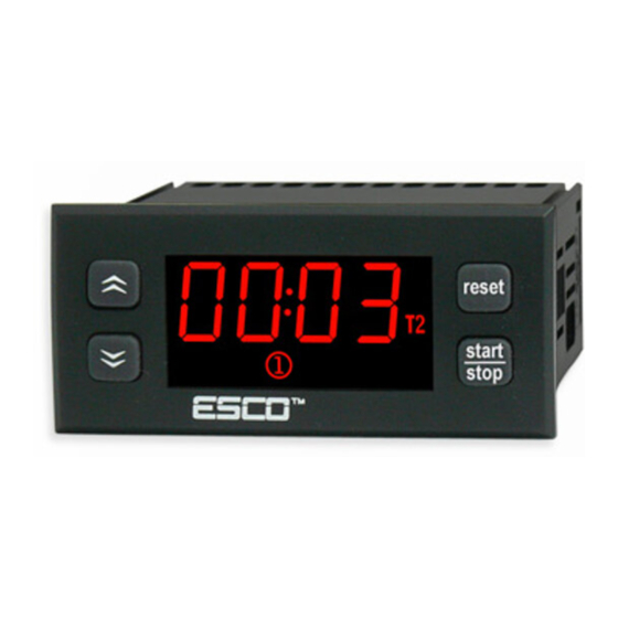
Summary of Contents for Esco TC-11
- Page 1 TC-11 MULTIFUNCTIONAL TIME 1.0 version RELAY (TIMER)
-
Page 2: Specifications
1. SPECIFICATIONS. D1: triggering START, STOP, PAUSE commands Digital input: D2: triggering RESET command Input signal: Potential free, by transmission closing impulse on contacts 2-3(RESET)and 4-5(START,STOP,PAUSE), minimum impulse time 100ms Output: Relay, 20A 250VAC Work mode: Time relay or time counter, 6 user-selectable operating modes with automatic or manual reset function Time settings:... - Page 3 4. TIMER HANDLING. 4.1. TIME SETTING T1. Press button for Using buttons reset reset 2 sec. Set the seconds value start start start and confirm with stop stop stop Diodes lights Then the minutes value up and seconds rate starts to blink. starts to blink.
-
Page 4: Parameters Programming
4.3. PARAMETERS PROGRAMMING. Enter the menu holding If the access to the menu reset reset is protected, command: Button for 5 sec. Until reset start start displays. the first parameter F10 stop stop start displays. Using stop buttons enter the password and confirm start with... - Page 5 5. TIMER WORK MODE. Timer operates in one of the following work modes. Depending on you needs, choose the suitable function for your system. Currently measured time T1 ( icon) or time T2 ( icon) is indicated on the display while working .
- Page 6 6. START/STOP/PAUZA/RESET COMMANDS. Timer can be controlled by buttons or and external signal applied to the D1 input. 6.1. BUTTONS CONTROL. Commands can be activated by buttons on a front panel. START start Press to start the countdown. Countdown passage of time is stop reset indicated on the display, by...
-
Page 7: Installation
7. OPERATING AFTER POWER LOSS. TC-11, depending on the version, is supplied with 230VAC or 12VAC/DC or 24VAC/DC. A power shortage may occur during the operation of the device. The F81 parameter determines the operation of the device after a power shortage. - Page 8 11.CONNECTION OF RECEIVING DEVICES Make sure that the electrical parameters of the device correspond to the parameters of the controller (maximum voltage, current rating, power). Diagram of connecting the receiving device: Receiving device TC-11 20(8)A 250VAC Power supply Power 230VAC...

Need help?
Do you have a question about the TC-11 and is the answer not in the manual?
Questions and answers