
Summary of Contents for TECOM TS1061
- Page 1 TS1061 Dual Wiegand Interface Installation Manual P/N MAINST-TS1061 • REV 2.5 • ISS 16AUG19...
- Page 2 Copyright © 2019 UTC Fire & Security Australia Pty Ltd. All rights reserved. Trademarks and The Challenger name and logo are trademarks of patents UTC Fire & Security Australia Pty Ltd. Other trade names used in this document may be trademarks or registered trademarks of the manufacturers or vendors of the respective products.
-
Page 3: Table Of Contents
Appendix B: User current draw ..........21 Appendix C: Operating temperature ......... 22 Appendix D: Cabling requirements ........... 23 System earthing ..............23 RS-485 cabling ..............23 Power supply to RS-485 devices ........23 TS1061 Dual Wiegand Interface Installation Manual... -
Page 4: Important Information
This is a Class B product. In a domestic environment this product may cause radio interference in which case the user may be required to take adequate measures. Contact information For contact information, see www.interlogix.com.au. TS1061 Dual Wiegand Interface Installation Manual... -
Page 5: Product Overview
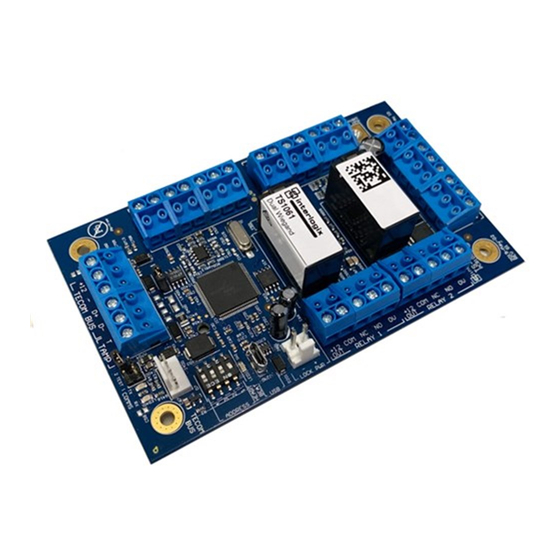
Product overview This manual applies to the TS1061 Dual Wiegand Interface. The Dual Wiegand Interface can be attached to a ChallengerPlus panel or a TS1066 Network Access Controller to provide two Wiegand interfaces, as well as additional inputs and relays. -
Page 6: Product Contents
If you need to return the unit, you must ship it in the original box. Table 1 below lists the items that are shipped with a TS1061 Dual Wiegand Interface. -
Page 7: Before You Begin
Before you begin When installing a TS1061 Dual Wiegand Interface, or any other parts of the system, you need to be aware of requirements for cabling and earthing, and plan accordingly. Refer to “Appendix D: Cabling requirements” on page 23. -
Page 8: Installing The Dual Wiegand Interface
Mounting in the enclosure The installation procedure is as follows: 1. Install four standoff board mounts for the TS1061 board on the enclosure. Refer to the ENC-LGE Large Enclosure Installation Manual for mounting locations. Figure 9 on page 18 indicates some possible mounting locations in the enclosure. -
Page 9: Dip Switch Settings
DIP switch settings The TS1061 Dual Wiegand Interface can be connected to a ChallengerPlus panel’s COMMS 1 or COMMS 2, or a Network Access Controller’s BUS 1 or BUS 2. The Interface is polled as a DGP. The addressing ranges that can be used depend on whether the Interface is connected to a ChallengerPlus or a Network Access Controller, as shown in Table 2 below. - Page 10 DGP 8 BUS 1 DGP 9 BUS 1 DGP 10 BUS 1 DGP 11 BUS 1 DGP 12 BUS 1 DGP 13 BUS 1 DGP 14 BUS 1 DGP 15 BUS 2 DGP 17 TS1061 Dual Wiegand Interface Installation Manual...
- Page 11 BUS 2 DGP 26 BUS 2 DGP 27 BUS 2 DGP 28 BUS 2 DGP 29 BUS 2 DGP 30 BUS 2 DGP 31 BUS 2 DGP 32 Legend: I = ON, O = OFF TS1061 Dual Wiegand Interface Installation Manual...
-
Page 12: Connections
Description Connect the TECOM BUS +12, TECOM BUS −, TECOM ChallengerPlus application: BUS D+ and TECOM BUS D− terminals to the ChallengerPlus panel’s COMMS 1 or COMMS 2 cable. Network Access Controller application: Connect the TECOM BUS +12, TECOM BUS −, TECOM BUS D+ and TECOM BUS D−... -
Page 13: Rs-485 Lan/Bus
BUS 1. Heart beat LED. See “LED indications” on page 19. RS-485 LAN/Bus The TS1061 Dual Wiegand Interface can be connected to a ChallengerPlus panel or Network Access Controller via the 4-pin RS-485 terminals (Figure 2 on page 8 item 1). - Page 14 Figure 3: Example TS1066 to TS1061 cable connections for RS-485 and lock power TS1061 TS1061 Note: Refer to the TS1066 Network Access Controller Installation Manual for information on the maximum total current draw allowed from a Network Access Controller. Using the RS-485 terminals: Use 2-pair twisted shielded data cable such as Belden 8723 to connect the Interface to a ChallengerPlus panel or Network Access Controller.
-
Page 15: Terminating The Rs-485 Lan
Network Access Controller to the Interface (items A and C). Note: Refer to the TS1066 Network Access Controller Installation Manual for information on the maximum total current draw allowed from a Network Access Controller. TS1061 Dual Wiegand Interface Installation Manual... -
Page 16: Door Lock Relay Wiring
EOL resistor values for Dual Weigand Interface can be different to ChallengerPlus panel or Network Access Controller it is connected to and must be set within the device using CTPlus or RAS install menu. TS1061 Dual Wiegand Interface Installation Manual... - Page 17 Alternatively, the ChallengerPlus panel or Network Access Controller can be configured to monitor inputs for two states (sealed and unsealed). This is accomplished by using one resistor in each circuit, as shown in Figure 6 on page TS1061 Dual Wiegand Interface Installation Manual...
-
Page 18: Wiegand Reader Connections
ChallengerPlus Programming Manual for details. Wiegand reader connections The TS1061 Dual Wiegand Interface can have two Wiegand devices, such as readers, connected to terminal blocks shown on Figure 2 on page 8, item 12. Figure 7 on page 15 details typical Wiegand reader wiring. -
Page 19: Door Wiring Example
Figure 7: Connecting a typical reader as a Wiegand device Weigand reader Note: Refer to MAINST-TS0862 TS0862 Smart Door Controller Installation Instructions manual for cable type and distance recommendations. Door wiring example TS1061 Dual Wiegand Interface Installation Manual... - Page 20 Figure 8 on page 17 consolidates the different connections of a TS1061 Dual Wiegand Interface into one diagram. It shows an example of using the Interface to connect to various parts of a door: • The door’s contact is connected to the first input on the Interface (Figure 2 on page 8, item 10) •...
- Page 21 Figure 8: Door wiring example TS1061 Dual Wiegand Interface Installation Manual...
-
Page 22: Earthing
See the ENC-LGE Large Enclosure Installation Manual for more information. Figure 9 below shows the earth leads in an example configuration of four TS1061 Dual Wiegand Interfaces in an ENC-LGE Large Enclosure, with a TS1066 Network Access Controller. -
Page 23: Led Indications
ChallengerPlus panel or Network Access Controller on the bus. Off indicates that the Interface is not correctly addressed, and/or that the ChallengerPlus panel / Network Access Controller are not programmed to poll the Interface’s DGP address. TS1061 Dual Wiegand Interface Installation Manual... -
Page 24: Appendix A: Standalone Current Draw
• All four inputs are sealed (10 kΩ EOL resistors) • The two on-board relays are not active • USB is not connected • The RS-485 system LAN is terminated and is connected to a terminated BUS port of TS1066 Network Access Controller. TS1061 Dual Wiegand Interface Installation Manual... -
Page 25: Appendix B: User Current Draw
(Figure 2 on page 8, item 12), with a combined maximum current draw of 450 mA. The maximum current draw for the relays is determined by the TS1066 Network Access Controller or TS-CHPLUS ChallengerPlus panel that the Interface is connected to. TS1061 Dual Wiegand Interface Installation Manual... -
Page 26: Appendix C: Operating Temperature
Interface is to operate for prolonged periods in an operating environment with a room temperature above 40°C, de-rate the user current drawn from the Interface according to the chart in Figure 10 below. Figure 10: Power derating chart TS1061 Dual Wiegand Interface Installation Manual... -
Page 27: Appendix D: Cabling Requirements
• RS-485 cabling System earthing TS1061 Dual Wiegand Interfaces can be connected to a ChallengerPlus control panel or Network Access Controller. Follow the system earthing recommendations provided in the ChallengerPlus Installation and Quick Programming Manual, or TS1066 Network Access Controller Installation Manual, respectively.
Need help?
Do you have a question about the TS1061 and is the answer not in the manual?
Questions and answers