Table of Contents
Advertisement
GENERAL PRODUCT INSTRUCTIONS
A.2.
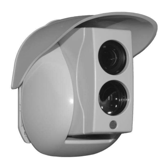
Presentation
DLFBe MANUAL
EN
DLFB (I) DLFB (A),
DLFB (C), DLFB (R)
DLFBe
CONTENTS
2
2
2
2
2
2
2
2
2
2
3
4
4
4
4
4
4
4
4
5
5
5
5
5
6
6
6
7
Document:
Revision:
Date:
Page:
C.
Start up of DLFBe
D.
Advanced Setting
F.
Installation of optical accessories
I.
26.NGP.1187
J
17/03/2010
1/16
8
8
8
8
8
8
9
9
9
10
10
10
11
11
12
12
13
14
14
14
15
15
15
15
16
Advertisement
Table of Contents

Summary of Contents for SEFI DLFBe Series
-
Page 1: Table Of Contents
Document: 26.NGP.1187 DLFBe MANUAL Revision: DLFB (I) DLFB (A), Date: 17/03/2010 DLFB (C), DLFB (R) Page: 1/16 DLFBe GENERAL PRODUCT INSTRUCTIONS CONTENTS Presentation Start up of DLFBe A.1. Foreword C.1. Introduction A.2. Presentation C.1.1. Handling the push buttons A.3. Contents of package C.1.2. -
Page 2: Presentation
Document: 26.NGP.1187 DLFBe MANUAL Revision: DLFB (I) DLFB (A), Date: 17/03/2010 DLFB (C), DLFB (R) Page: 2/16 PRESENTATION A.1. FOREWORD These instructions apply to the « DLFBe » linear smoke detector revision « C02 » and next ones. This revision is indicated on the detectors signal label. A.2. -
Page 3: Parts List
Document: 26.NGP.1187 DLFBe MANUAL Revision: DLFB (I) DLFB (A), Date: 17/03/2010 DLFB (C), DLFB (R) Page: 3/16 A.6. PARTS LIST 1 IP cap 8 Vertical rotating axis screw 2 Optical block 9 Push buttons 3 Receiver 10 Horizontal setting wheel 4 Transmitter 11 Remote control connector 5 Indicator light (red, yellow or green) -
Page 4: Installation
Document: 26.NGP.1187 DLFBe MANUAL Revision: DLFB (I) DLFB (A), Date: 17/03/2010 DLFB (C), DLFB (R) Page: 4/16 INSTALLATION B.1. DOCUMENTS REQUIRED FOR INSTALLATION These instructions. Instructions relating to installed CIE (Control and Indicating Equipment) fire alarm panel. B.2. SPECIFIC INSTALLATION TOOLS In addition to ordinary electrician tooling, the following is needed: –... -
Page 5: Part Space Requirement
Document: 26.NGP.1187 DLFBe MANUAL Revision: DLFB (I) DLFB (A), Date: 17/03/2010 DLFB (C), DLFB (R) Page: 5/16 B.5. PART SPACE REQUIREMENT B.5.1. Transmitter/Receiver (« T/R ») Hatched areas should remain cleared for the installation, setting and maintenance work. The space requirements shown below, above, and on the right of the unit, should be at least 20 mm. -
Page 6: Installation Of The Reflector
Document: 26.NGP.1187 DLFBe MANUAL Revision: DLFB (I) DLFB (A), Date: 17/03/2010 DLFB (C), DLFB (R) Page: 6/16 B.6.2. Installation of the reflector Choose the number of reflectors based on the distance to be covered and the accessories that are used (See § G) Check the space requirement of the unit chosen on page n°13 §... -
Page 7: Line Connection Diagrams
Document: 26.NGP.1187 DLFBe MANUAL Revision: DLFB (I) DLFB (A), Date: 17/03/2010 DLFB (C), DLFB (R) Page: 7/16 Terminal block of the Relay and Conventional version: Terminal block mark Relay Conventional “+” of power supply “+” line input “-” of power supply “-”... -
Page 8: Introduction
Document: 26.NGP.1187 DLFBe MANUAL Revision: DLFB (I) DLFB (A), Date: 17/03/2010 DLFB (C), DLFB (R) Page: 8/16 START UP OF DLFBe C.1. INTRODUCTION C.1.1. Handling the push buttons The detector has 4 buttons respectively marked from « A » to « D » ; each valid press on one of the buttons is confirmed by the turning on of the green indicator light or turning off if it was on. -
Page 9: Calibration Check
Document: 26.NGP.1187 DLFBe MANUAL Revision: DLFB (I) DLFB (A), Date: 17/03/2010 DLFB (C), DLFB (R) Page: 9/16 8. Wait until the steady green light signal comes on ; 9. Repeat steps 4 to 9 as long as the voltage can be increased on the voltmeter ; 10. -
Page 10: Fire Alarm Test
Document: 26.NGP.1187 DLFBe MANUAL Revision: DLFB (I) DLFB (A), Date: 17/03/2010 DLFB (C), DLFB (R) Page: 10/16 C.3.3. Fire alarm test That test allows to check that the detector switches properly to fire alarm with the use of the fire alarm simulation filter The test procedure is as follows: The detector has been on standby for at least 1 min ;... -
Page 11: Visualisation Of Active Configuration
Document: 26.NGP.1187 DLFBe MANUAL Revision: DLFB (I) DLFB (A), Date: 17/03/2010 DLFB (C), DLFB (R) Page: 11/16 Note (1): This setting only concern the relay version. Note (2): These settings are not compatibles with the NF mark requirements. Note (3): Automatic resetting of the alarm after the time indicated when the alarm cause is no longer detected. -
Page 12: Fault Emulation
Document: 26.NGP.1187 DLFBe MANUAL Revision: DLFB (I) DLFB (A), Date: 17/03/2010 DLFB (C), DLFB (R) Page: 12/16 D.4. FAULT EMULATION This test is used to put the linear smoke detector in fault condition, without however sending such fault to the CIE. The test procedure is as follows: •... -
Page 13: Technical Features
Document: 26.NGP.1187 DLFBe MANUAL Revision: DLFB (I) DLFB (A), Date: 17/03/2010 DLFB (C), DLFB (R) Page: 13/16 TECHNICAL FEATURES MECHANICAL FEATURES FEATURES ELECTRIQUES Parameters Features Parameters Features Space requirement: Power supply From 12 Vdc to 30 Vdc Width (W): 135,0 mm ; Height (H): 170,0 mm Relay DLFBe consumption upon Rated under 24 Vdc: •... -
Page 14: External Diaphragm
Document: 26.NGP.1187 DLFBe MANUAL Revision: DLFB (I) DLFB (A), Date: 17/03/2010 DLFB (C), DLFB (R) Page: 14/16 INSTALLATION OF OPTICAL ACCESSORIES F.1. EXTERNAL DIAPHRAGM Refer to § B.4.3 prior to using the external diaphragm. In case the detector is used in a highly intense environment, it is necessary to use the external diaphragm that reduces the dazzle phenomenon. -
Page 15: Selection Of Number Of Reflectors
(between the optical block and the wall mounting) is damaged, after the legal period. MARKING EN 54-12: 2002 line detectors using an optical light SEFI beam Rue René Cassin EN 54-17: 2005 short-circuit isolators... -
Page 16: Installation And Starting Up Sheet
Document: 26.NGP.1187 DLFBe MANUAL Revision: DLFB (I) DLFB (A), Date: 17/03/2010 DLFB (C), DLFB (R) Page: 16/16 INSTALLATION AND STARTING UP SHEET This sheet describes the main steps to be completed to install and start up the detector Estimate the distance between the detector and the reflector Is the detector exposed to direct sunlight (See B.4.3) ? If Yes, change the intended location of the detector Is the reflector exposed to directly sunlight (See B.4.3) ?
Need help?
Do you have a question about the DLFBe Series and is the answer not in the manual?
Questions and answers