Table of Contents
Advertisement
Quick Links
Hum Bug
REFERENCE MANUAL
CONTENTS
Introduction.................................................. 3
Theory Of Operation.................................... 4
Installation ................................................... 6
Controls ....................................................... 7
Input Signal ................................................. 7
Noise Generated By Monitors ..................... 8
Sources Of Complex Noise ......................... 9
Adaptation Rate........................................... 9
Front Panel................................................ 10
Back Panel ................................................ 11
Trouble Shooting ....................................... 12
Specifications ............................................ 18
Warranty And Contacts ............................. 18
Quest Scientific
Advertisement
Table of Contents

Summary of Contents for Quest Scientific Hum Bug
-
Page 1: Table Of Contents
Hum Bug REFERENCE MANUAL CONTENTS Introduction..........3 Theory Of Operation........4 Installation ........... 6 Controls ............7 Input Signal ..........7 Noise Generated By Monitors ..... 8 Sources Of Complex Noise ......9 Adaptation Rate........... 9 Front Panel..........10 Back Panel ..........11 Trouble Shooting ........ - Page 2 Page 2 Hum Bug Reference Manual Quest Scientific...
-
Page 3: Introduction
Simply insert it into the signal path of your recording system and it will automatically eliminate noise without any need for adjustment. The Hum Bug is not a filter. It is a new class of instrument capable of eliminating electrical interference from analogue signals without creating phase shifts, frequency loss, amplitude errors, DC shifts, time delays, or digital distortion. -
Page 4: Theory Of Operation
1 kHz. Therefore, the noise replica may lag behind if the noise characteristics suddenly change. Under these conditions, some noise will transiently appear on the output while the Hum Bug adapts to the new characteristics. - Page 5 Hum Bug Reference Manual Page 5 Quest Scientific...
-
Page 6: Installation
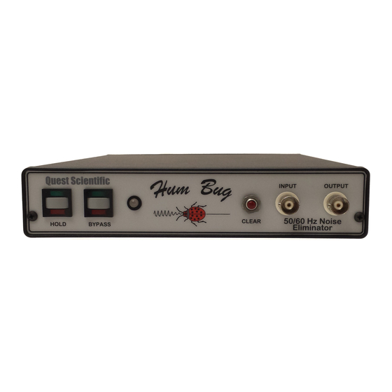
Input and output connectors are located on the front panel and the power switch is on the back of the unit. Insert the Hum Bug at any point in the chain of instruments after the signal from your electrode or sensor is buffered and before the signal is connected to your oscilloscope, computer, and/or tape recorder. -
Page 7: Controls
The Clear Button is the only other control function on the front panel. Pushing it will clear the noise replica and force the Hum Bug to generate a new noise replica from scratch. In effect, this causes the Hum Bug to immediately forget the noise waveform. This function is seldom necessary since the Hum Bug automatically adapts to changing noise conditions. -
Page 8: Noise Generated By Monitors
In most cases it will differ from the power mains and will not be recognized as noise by the Hum Bug. Fortunately, following the guidelines outlined below will help eliminate this form of electrical interference. -
Page 9: Sources Of Complex Noise
This output noise will then decay with a time constant related to the adaptation rate of the Hum Bug. Under ideal conditions this time constant is in the order of 5 to 10 seconds. In practice, the exact time constant is difficult to predict because it depends on the change in noise amplitude, the harmonic content of the noise, and the magnitude of the noise relative to ongoing physiological activity. -
Page 10: Front Panel
Using HOLD during these manipulations will keep the Hum Bug from chasing the transient noise. As a result, effective cancellation of ongoing noise can resume immediately after the manipulation is complete. -
Page 11: Back Panel
Hum Bug Reference Manual Page 11 BACK PANEL Quest Scientific... -
Page 12: Trouble Shooting
However, on occasion you may encounter a problem. In some cases the problem may be based on a simple misunderstanding about the operation of the device and in others, the Hum Bug may need repair. The following procedures will help you solve any problems as quickly as possible. - Page 13 Hum Bug Reference Manual Page 13 Step Three: Observe the operation of the Hum Bug in BYPASS mode. In this mode the input and output of the Hum Bug should be identical. Here are some explicit steps to help you with the procedure.
- Page 14 The LED Indicator should turn green. • After a brief pause, the Hum Bug will begin to adapt to the noise on the input and the noise on the output should gradually decrease to minimal levels. During this phase the LED Indicator should flash red.
- Page 15 Contact Quest Scientific for advice. 2. The 50/60 Hz noise on the output of the Hum Bug increases to very high levels even when little or no noise is present on the input.
- Page 16 C. The output of the Hum Bug has too much baseline noise (random, wide-band noise). 1. Are you attempting to use the Hum Bug on very low level signals (less than 1 mV)? If so, circuit noise from the Hum Bug may be detected on the output.
- Page 17 Hum Bug Reference Manual Page 17 • Remove any additional grounding wires connected to the chassis of the Hum Bug. These additional ground wires will make inappropriate connections between grounds in your setup and the grounds in the power mains.
-
Page 18: Specifications
E-Mail quest_sale@quest-sci.com QUEST SCIENTIFIC LIMITED WARRANTY: Quest Scientific warrants this product to be free of defects in material and workmanship for a period of two years from date of original purchase. Contact Quest Scientific for further information. © Copyright 1997 Quest Scientific Instruments Inc.
Need help?
Do you have a question about the Hum Bug and is the answer not in the manual?
Questions and answers