Advertisement
GUIDELINES
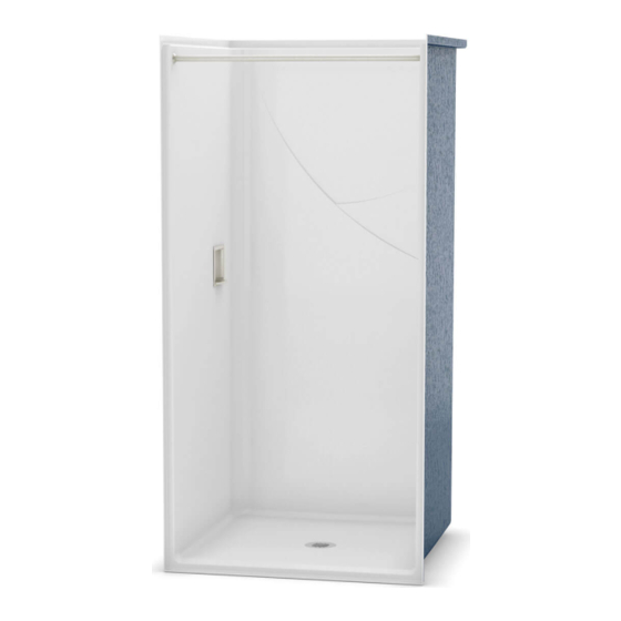
FOR UNIT
INSTALLATION
View Installation Video - Scan QR code with a mobile device
Voir Vidéo d'installation - Balayer QR code avec un dispositif mobile
Ver video de instalación - Escanear código QR con un dispositivo mobil
OPS-3636
OPS-3636-RS
OPS-4248
OPS-4248-RS
OPS-6030
OPS-6030-RS
OPS-6036
OPS-6036-RS
OPTS-6032
Read carefully before proceeding. TO BE KEPT BY THE END USER.
PLEASE READ INSTRUCTIONS CAREFULLY BEFORE PROCEEDING
Before starting
Upon reception, check if your shower is in good condition and make sure that all parts are included. If you have a problem, please
contact immediately your distributor.
Required equipment
• Level
• Measuring tape
• Electric drill
• #8 x 1" wood screws • Square
• Silicone
• Safety goggles
• Wood shims
• Phillips screwdriver
• Cement or similar composite material
WARNING:
For optimum operation, it is important that the unit be installed perfectly on a leveled floor. Handle metal parts with
care. During installation, protect shower floor with the cardboard packaging. This will prevent damaging the finish.
DO NOT BUILD THE SURROUNDING STRUCTURE BEFORE RECEIVING YOUR UNIT. Structure measurements should be
verified against the unit to ensure a proper fit.
The grab bars and seats must be installed before unit installation.
Consult local building codes to make sure the installation complies with standards.
MAAX is not responsible for problems caused by installations that were not conducted in compliance with the directives
in this guide.
In accordance with standards, the finished entrance height of shower stalls must not exceed ½ inch (13 mm).
Because of the possible water leaks between the lip of the shower and the curtain, MAAX RECOMMENDS THE
INSTALLATION OF A FLOOR DRAIN OUTSIDE THE UNIT, in rooms where the aforementioned units will be installed.
106027-106028-106029-106030-106031-106032-106033
106064-106065-106066-106067-106068-106069-106070
106034-106035-106036-106037-106038-106039-106771-106772-106773
106071-106072-106073-106074-106075-106076-106774-106775-106776
106040-106041-106042-106043-106044-106045-106777-106778-106779
106077-106078-106079-106080-106081-106082-106780-106781-106782
106057-106058-106059-106060-106061-106062-106063
Keep the serial number for the unit
• Pencil
ATTENTION
Outlook Plus Series
106053-106054-106055-106056
106083-106084-106085-106086
A two person installation
is recommended.
10032588
Advertisement
Table of Contents

Related Manuals for MAAX Outlook Plus Series


Summary of Contents for MAAX Outlook Plus Series
- Page 1 The grab bars and seats must be installed before unit installation. Consult local building codes to make sure the installation complies with standards. MAAX is not responsible for problems caused by installations that were not conducted in compliance with the directives in this guide.
-
Page 2: Installation
INSTALLATION STEP FREE SPACE The bathroom configuration must include a clearance zone to allow the user to have access to the unit. In order to respect these various standards, refer to the table below. It is very important that the free space respect the dimensions. - Page 3 INSTALLATION STEP FRAMING A sturdy frame is required to ensure stability of the unit, once installed. For units equipped with a stainless steel soap dish, make sure that there is no stud behind the soap dish hole. Allow an accessway to the faucet Construct the alcove in accordance with Fig.
-
Page 4: Control Area
INSTALLATION STEP CONTROL AREA The control area must be inside a target zone and must not exceed this zone in order to respect the various standards. Fig. A. The control area can differ slightly from one standard to another. Refer to the table below. NOTE: If unit is with a complete compliant package, the control hole will be factory drilled. -
Page 5: Valve Installation
INSTALLATION STEP VALVE INSTALLATION A trap door measuring at least 30" x 28" (762mm x 711mm) behind EACH shower model is highly recommended to give access to the valve and plumbing for maintenance and repairs. a) At the height the valve will be installed (dim. A) (45" - 48" (1143mm - 1219mm) for showers and 32"(813mm) for tub shower), fasten a 3 in. - Page 6 INSTALLATION STEP HAND-HELD SHOWER INSTALLATION Drill a 1" diameter hole in the recommended target zone marked with the dotted line rectangle as shown in Fig. A. Apply a bead of silicone on the inside surface of the hand-held shower connector and insert it in the previously drilled hole as shown in Fig.
- Page 7 INSTALLATION STEP DRAIN ON SHOWER INSTALLATION Cut drain pipe flush to the floor. Fig. A. Apply a bead of silicone under flange of drain head. Insert drain head into the drain hole of the unit. Tighten locknut with friction ring and gasket to secure shower drain to shower floor. Fig. B. Before final installation of the drain, the unit (shower or tub-shower) has to be completely installed.
-
Page 8: Unit Installation
INSTALLATION STEP UNIT INSTALLATION A) Before placing the unit in the alcove, measure the depth. Fig.A. B) Using the depth project and trace a line as shown in fig.B. C) Place the unit in the alcove, use the traced line as a reference to help in positionning the unit. Verify that everything fits (drain pipe, valve and soap dish). - Page 9 INSTALLATION STEP UNIT INSTALLATION A) Apply a thin layer of mortar. Leave a gap of at least 5 inches around the drain hole as shown. Fig.A. B) Tip to the front the unit and place it on the previously marked line as shown. Fig.B. Make sure that everything (drain, pipe and valve) is on the right place.
- Page 10 INSTALLATION STEP OPTIONAL SOAP DISH INSTALLATION The soap dish must be installed after having positioned the unit in the frame. If the option is chosen an opening for inserting the soap dish will be factory drilled. Install the spring at the center of the soap dish support. Fig. A. Then insert the support in the opening so that the support with the spring is compressed between the backing of the unit and the back wall.
- Page 11 INSTALLATION STEP FASTENING OF THE UNIT TO THE FRAME Level and square the unit. Fasten unit using #8 screws. Start by fastening a screw in each bottom corner of the unit. Drive in the other screws after checking that the unit is correctly positioned, leveled and squared. Fasten screws into the fastening flange, 8" (20cm) apart along the vertical sides and the floor.
- Page 12 INSTALLATION STEP VALVE INSTALLATION WARNING: Upon reception, make sure that all parts of the valve are included. If you have a problem, please contact immediately your distributor. Always cut off the water supply before removing or disassembling a valve. Turn the valve on to release any water pressure and to make sure the water supply has indeed been cut off.
- Page 13 INSTALLATION STEP DRAIN FINAL INSTALLATION A) Insert rubber calking gasket (1) over drain pipe as shown. B) Screw calking nut (2) over drain head. C) Fasten calking nut with locking wrench (3) provided to secure shower drain to pipe. Fully tighten to ensure waterproofing. Then remove the locking wrench.
- Page 14 INSTALLATION STEP FINISHED FLOOR INSTALLATION Important: The finished height of the threshold must comply with the following standards: US: maximum height of 1/2" (13mm) in accordance with ADA/ANSI/ICC A117.1 (Accessible and Usable Buildings and Facilities). This requirement does not apply to tub-showers. DAM PROFILE ’’...
- Page 15 INSTALLATION STEP FINISH Finishing panels (plasterboard, ceramic tile, etc.) should completely cover the fastening flange (Fig. A). The joint between the wall panels and the finishing panels can be covered with a joint compound, a plastic stripe, or a tile strip. To prevent water infiltration, apply a bead of silicone between the floor and the threshold of the unit.
- Page 16 LIMITED WARRANTY — UNITED STATES MAAX Bath Inc. offers express limited warranty on each of its products. This warranty extends only to the original owner/end-user for personal household use. For commercial uses, additional limitations apply. For accessing product Limited warranty please visit: www.maax.com/us-warranty...
Need help?
Do you have a question about the Outlook Plus Series and is the answer not in the manual?
Questions and answers