
Related Manuals for Cimarron ARCONTROL BASE

Summary of Contents for Cimarron ARCONTROL BASE
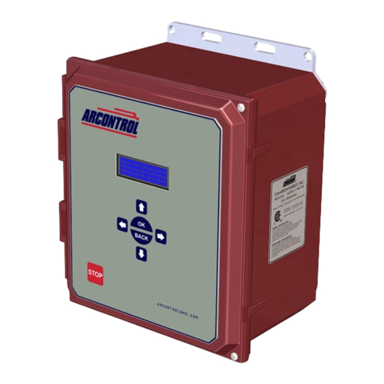
- Page 1 ARCONTROL™ BASE USER MANUAL Revision B 2020 © Copyright Cimarron Energy https://www.arcontrolbms.com March 2020...
-
Page 2: Table Of Contents
Table of Contents 1.0 Introduction....................... 1 1.1 Hardware Installation ......................1 1.2 Wiring for Operation ......................3 1.3 Application Information ..................... 6 1.4 Ignition Module ......................... 7 2.0 System Overview ....................... 7 2.1 User Interface ........................7 2.2 System Splash Window ...................... 8 2.3 System Menu ........................ -
Page 3: Introduction
• Proper earth grounding per local electrical codes must be utilized in the installation. • If the ARControl is used in a manner not specified by Cimarron Energy, Inc., the protection provided by the equipment may be impaired. • If the BMS Module (1870-511) is used in conjunction with the ARControl it must be mounted externally of the ARControl in order for the ARControl to remain regulatory compliant. - Page 4 Provided Wiring Harness Follow these steps to install the ARControl: 1. Locate and open the hardware kit. 2. Attach the mounting flanges to the back of the ARControl with Ignition Module the supplied hardware. B PWR GND 3. Holes will need to be drilled in MODULE PORT the bottom of the enclosure to Permissive...
-
Page 5: Wiring For Operation
If there are questions not answered AUXIO DIGITAL by this manual or the wiring diagrams, please call Cimarron Energy at 1-844-746-1676 for assistance. OUTPUTS DOUT+ 1.2.1 Connecting the Power... - Page 6 1.2.3 Connecting a TRANS- DUCER Thermocouple (if used) PORT Thermocouple TC1 is the only thermocouple input. The THERMO- input has a readout on the system main COUPLE PORTS screen and the thermocouple value gets recorded in the data logs (Image 1.2.3). RS485 PORT B PWR GND...
- Page 7 1.2.6 PERMISSIVE (DIN) Input The PERMISSIVE (DIN) input comes 1MΩ 5VDC B PWR GND with a jumper installed from the MODULE PORT factory. To use the PERMISSIVE 10KΩ (DIN) input, remove the jumper and DIGITAL INPUTS Permissive IN connect to an external PLC’s dry B PWR GND contact switch output or some other MODULE PORT...
-
Page 8: Application Information
RS485 PORT 1.3 Application Information 1.3.1 Alarm Output B PWR GND The alarm output is active when the ARControl is in an MODULE PORT alarm state. The alarm behaves as an open switch when DIGITAL it is active. External alarm circuitry should be limited to OUT TO DOUT- ALARM... -
Page 9: Ignition Module
2 System Overview 2.1 User Interface The system user interface (Image 2.1.1) consists of a text display and seven keys (Table 2.1.1) that are used for menu navigation, selecting options on menu items and entering or exiting menus. The text display provides information regarding menus, submenus, system modes, selectable options, current mode operation states and alarms. -
Page 10: System Splash Window
2.2 System Splash Window When the system powers up the System Splash window (Image 2.2.1) will appear for 2 seconds. The splash window contains the company name, system name and finally the system’s firmware identification version number and revision level. A R C O N T R O L ™... -
Page 11: System Menu Symbols
2.4 System Menu Symbols The symbols shown in the System Menu signify the following: → → Indicates current menu selection → → ≡ Indicates a submenu ≡ ≡ ≡ Indicates an actionable menu item < > < > < > <... -
Page 12: Thermocouple 1 (Tc1)
M O D E A U T M A T T A T E A D D ° BACK → ≡ ≡ E R V STOP ARCONTROLBMS.COM Use the UP or DOWN key and move arrow to SETTINGS MENU A U T O M A T I C Move arrow →... -
Page 13: Data Logs
→ S E R V C A L 5 2 5 Firmware ID number Current mode Ignition duration Delay duration setting setting C U R R S PERMISSIVE (DIN) input Battery voltage Solar input voltage X X X Firmware CRC value A N D Image 2.6.1 ·... - Page 14 Data is broken down into three groups, System data, Digital data and Analog data. Both log types contain the same data as follows: (Tables 2.7.2, 2.7.3, 2.7.4) GROUP HEADER DESCRIPTION Time stamp in the format YYYYMMddhhmmss. This time stamp format TIME STAMP SYSTEM DATA facilitates data manipulation and plotting.
-
Page 15: Modbus Protocol
2.7.2 Clearing the Data Logs The Clear Data Logs command is located in the Service Info sub-menu. Pressing OK will prompt a confirmation screen confirming whether or not to delete all of the previously log data (Image 2.7.2). S E R V C A L 5 2 5 C U R R S... - Page 16 2.8.2 Modbus Configuration Registers Modbus configuration registers are as follows (Table 2.8.2): REGISTER NAME DESCRIPTION DEFAULT TYPE NUMBER Unused/Reserved for expansion. UNUSED Always reads 0. FIRMWARE VERSION Current version of the firmware UINT16 FIRMWARE REVISION Current revision of the firmware UINT16 FIRMWARE CRC Cyclic Redundancy Check most...
- Page 17 REGISTER NAME DESCRIPTION TYPE NUMBER Mode State vs Register Value CURRENT SYSTEM STATE State Register Value AUTOMATIC UNKNOWN UINT16 STOPPED PILOT ON IGNITE PILOT FAILED PERMISSIVE (DIN) OPEN LOW BATTERY DELAY BMS LOCKOUT CONTINUOUS UNKNOWN STOPPED PILOT ON IGNITE FLAME LOST PERMISSIVE (DIN) OPEN LOW BATTERY...
-
Page 18: System Settings
3 System Settings The Settings Menu allows the user to see the current system settings, modify the settings and commit them to the system. This section will explain what each setting is, how to enter the Settings Menu and how to change the setting options. -
Page 19: Settings Menu
3.2 Settings Menu To change the settings you must enter the Settings Menu. Follow these steps to enter the Settings Menu: 1. Use the UP or DOWN key and select SETTINGS MENU (Image 3.2.1). 2. Press the OK key. M O D E C U R M O D C U R R... -
Page 20: Changing System Settings
3.3 Changing System Settings Follow these steps to change system settings: 1. Using the UP and DOWN key to move the arrow on the left hand side of the menu and navigate to desired setting. 2. Using LEFT and RIGHT key scroll through the possible options for the setting. For example, change the ignition duration to 30 seconds (Image 3.3.1) 3. -
Page 21: Setting The Date And Time
3.4 Setting the Date and Time Setting the Date Follow these steps to set the system date. 1. Use the UP or DOWN key to SETTINGS 0 0 / 0 0 0 0 MENU. 2. Press the OK key. 3. In the submenu, use the UP or DOWN key and scroll to DATE. -
Page 22: System Operation
4 System Operation WARNING! Failure to comply with the following safety warning(s) may result in serious personal injury or death. • Do not open when in operational mode. Each mode of operation, AUTOMATIC, CONTINUOUS, and MANUAL have multiple operation and alarm states. Additionally, information about the current state and prompts for actionable menu items is presented in the main menu state additional information entry (STATE ADDTL INFO) (Table 4.1). -
Page 23: Automatic Mode
4.1 AUTOMATIC Mode 4.1.1 AUTOMATIC Mode Overview AUTOMATIC mode provides a timed ignition period and a settable delay period between the end of the ignition period and the transition to the PILOT FAILED alarm state. Additionally, AUTOMATIC mode offers automatic re-ignition if flame is lost. -
Page 24: Automatic Mode Operation States
4.1.2 AUTOMATIC Mode Operation States The AUTOMATIC mode has four states of operation, these include (Table 4.1.1): STATE DESCRIPTION The system is waiting to start ignition. STOPPED Start ignition has been initiated and the system is attempting to detect a flame. IGNITE PILOT ON A flame has been detected. - Page 25 IGNITE state Once in the IGNITE state, the system ignites up to 30 or 10 seconds depending on the current ignition duration setting if flame is not detected. If flame is not detected in the 30 or 10 seconds span, the system transitions to the DELAY state. If the system detects a flame within the 30 or 10 seconds span, then the system transitions to the PILOT ON state.
-
Page 26: Automatic Mode Alarm States
The text display shows the run time in the format “mm:ss” where “mm” represents the number of minutes and “ss” represents the number of seconds remaining in the DELAY state countdown (Image 4.1.7). M O D E : A U T O M A T I S T A T E : D E L →... - Page 27 If the user does press the OK key, then an alarm clear confirmation screen appears (Image 4.1.9). When prompted, confirm your selection on the alarm clear confirmation screen. C A U T O N ! C A U T O N ! E N S U R E S A F E C L E A R...
- Page 28 PERMISSIVE (DIN) OPEN state If at any time during operation the external dry contact switch connected at the PERMISSIVE (DIN) input goes open, then the system transitions to the PERMISSIVE (DIN) OPEN state, unless the system is in an alarm state already (Image 4.1.12).
-
Page 29: Continuous Mode
4.2 CONTINUOUS Mode 4.2.1 CONTINUOUS Mode Overview CONTINUOUS mode offers a continuous ignition without a timeout period. In CONTINUOUS mode the system ignites if flame it is not detected and goes back to igniting if the flame is lost. Also, in CONTINUOUS mode, if the system ignites for 30 minutes without establishing flame presence, the system continues igniting but activates the alarm output. -
Page 30: Continuous Mode Operation States
4.2.2 CONTINUOUS Mode Operation States The CONTINUOUS mode has four states of operation, these include (Table 4.2.1): STATE DESCRIPTION The system is waiting to start ignition. STOPPED Start ignition has been initiated and the system will attempt to detect a flame for 30 minutes. IGNITE FLAME PRESENT A flame has been detected and the system is operating. - Page 31 IGNITE state Once in the IGNITE state, if a flame is not detected the system will continue to attempt ignition for up to 30 minutes. If flame is not detected within 30 minutes, the system transitions to the IGNITE WARNING state where it keeps igniting indefinitely.
-
Page 32: Continuous Mode Alarm States
The text display shows the run time in the format “dddddddd:hh:mm:ss” where “dddddddd” represents the number of days that the system has been in the IGNITE WARNING state. Next, “hh” represents the number of hours (in 24-hour format), “mm” represents the number of minutes and “ss” represents the number of seconds in the FLAME PRESENT state (Image 4.2.7). - Page 33 If the user does press the OK key, then an alarm clear confirmation screen appears (Image 4.2.9). When prompted, confirm your selection on the alarm clear confirmation screen. C A U T O N ! C A U T O N ! E N S U R E S A F E C L E A R...
-
Page 34: Manual Mode
4.3 MANUAL Mode 4.3.1 MANUAL Mode Overview MANUAL mode provides the user manual control of the ignition timing, the user is required to hold the OK key for the system to ignite. Once the OK button is released and flame is present the system goes to pilot on otherwise the system sits in idle to allow the user to do the next manual attempt. -
Page 35: Manual Mode Operation States
4.3.2 MANUAL Mode Operation States The MANUAL mode has three states of operation, these include (Table 4.3.1): STATE DESCRIPTION The system is waiting to start ignition. STOPPED The user presses, and holds, the OK key until they are confident the pilot or burner is lit. The system will look at the flame sense system. - Page 36 IGNITE state In the IGNITE state, the system ignites for as long as the user keeps the OK key pressed and held (Image 4.3.5). This allows the user to ignite until they are confident the pilot or burner is lit. Once the OK key is released, the system will transition to the PILOT ON state if flame is present or the STOPPED state if flame is not present (Image 4.3.6).
-
Page 37: Manual Mode Alarm States
4.3.3 MANUAL Mode Alarm States The MANUAL mode has three alarm states, these include (Table 4.3.2): STATE DESCRIPTION If at any time the flame is determined to be absent in the PILOT ON state, the system transition FLAME LOST to the FLAME LOST state. The LOW BATTERY state appears any time the system is battery voltage drops below 11.5V for LOW BATTERY 12V operation or 23V for 24V operation. - Page 38 A L A R M ! A L A R M ! A L A R M FLAME LOST A L A R M : L O T A I L E D alarm state S T A T E B V = X X .
-
Page 39: Troubleshooting
5 Troubleshooting PROBLEM SOLUTION System will not exit PERMISSIVE (DIN) Make sure PERMISSIVE (DIN) input is closed circuit or jumped short. open alarm state System will not spark Make sure ignition module address dip switch is set to 1. System will not detect flame Make sure that grounding wire is attached to the pilot/burner chassis. -
Page 40: Maintenance & Service
12 Volt 12 Amp Hour SLA Battery 143176 12" Type K Thermocouple, ¼” diameter, ½” NPT Please contact Cimarron Energy, Inc. for information in regard to maintenance, parts, or service: 1-844-746-1676 11025 Equity Dr., Suite 200, Houston, TX 77041 www.cimarronenergy.com 7 Approvals •... -
Page 41: Equipment Ratings
8 Equipment Ratings PARAMETER MINIMUM TYPICAL MAXIMUM UNITS Ambient Temperature Relative Humidity (Non-Condensing) Enclosure Rating NEMA 4X Operating Voltage 12 or 24 Operating Current 0.015 Solar Voltage 12 or 24 Solar Current ALARM Output Voltage In ALARM Output Current (DOUT) Pilot Status Voltage Output 12 or 24 (DOUT) Pilot Status Current Output Thermocouple 1 &... - Page 42 This Page Intentionally Left Blank...
- Page 43 Revision B 2020 © Copyright Cimarron Energy https://www.arcontrolbms.com March 2020...
Need help?
Do you have a question about the ARCONTROL BASE and is the answer not in the manual?
Questions and answers