
Subscribe to Our Youtube Channel
Related Manuals for Magnetek LaserGuard Mini

Summary of Contents for Magnetek LaserGuard Mini
- Page 1 LaserGuard Mini Laser Collision Avoidance System April 2020 Part Number: 147-20127 R0 © Copyright 2020 Magnetek...
-
Page 2: Table Of Contents
Table of Contents LaserGuard Mini System Information ...................... 7 1.1. Model Numbers ............................ 7 1.2. Class 1 Laser Sensor ........................... 7 1.3. System Description ..........................7 1.4. System Specifications .......................... 8 1.5. Laser Support Unit Assemblies ......................9 Electrical Installation ..........................11 2.1. - Page 3 This manual may not be reproduced in whole or in part by any means whatsoever without the expressed written permission of MAGNETEK.
- Page 4 It is the responsibility of the owners, users and operators of the Magnetek Products to know, understand and follow all of these requirements. It is the responsibility of the employer to make its employees aware of all of the above listed requirements and to make certain that all operators are properly trained.
- Page 5 DANGER, WARNING, CAUTION and NOTE Statements Read and understand this manual before installing, operating or servicing this product. Install the product according to this manual and local codes. The following conventions indicate safety messages in this manual. Failure to heed these messages could cause fatal injury or damage products and related equipment and systems.
- Page 6 WARNING The collision avoidance unit and limit switches should never be used as a regular stopping device. They are intended to be protective devices. LaserGuard Mini Instruction Manual April 2020 Page 6 of 25...
-
Page 7: Laserguard Mini System Information
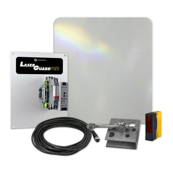
This allows for very accurate measurements and energy efficiency. The laser used in the LaserGuard Mini system is set to measure distances from 8 in. to 164 ft (0.2-50m). The laser has a visible red light beam, which makes system alignment very easy. -
Page 8: System Specifications
[0.91 kg] [2.54 kg] Reflector 2 x 2 ft. Dimensions [0.61 x 0.61 m] Laser Cable Length 32.8 ft. [10m], 82 ft. [25m], 131.2 ft. [40m], or 246 ft. [75m] LaserGuard Mini Instruction Manual April 2020 Page 8 of 25... -
Page 9: Laser Support Unit Assemblies
WASHER, LOCK #10 SCREW COMBO, #10-32 X 5/8 PRODUCT LABEL 2.5” DIN RAIL SPDT RELAY, 24VDC COIL GROUND TERMINAL BLOCK END-STOP Figure 2: Laser Support Unit (P/N: LGM-LSU-OPEN) Assembly for LGM-OPEN-X-X LaserGuard Mini Instruction Manual April 2020 Page 9 of 25... - Page 10 SPDT RELAY, 24VDC COIL GROUND TERMINAL BLOCK END-STOP LASER MOUNTING BRACKET LASER SENSOR SCREW, #10-32 X 1-1/4 NEMA 4X ENCLOSURE 0.5M LASER CABLE Figure 3: Laser Support Unit (P/N: LGM-LSU-4X) Assembly for LGM-4X LaserGuard Mini Instruction Manual April 2020 Page 10 of 25...
-
Page 11: Electrical Installation
Voltage Considerations Check the specification table or system drawings for proper line input voltage and supported relay voltages. If there are any questions, contact Magnetek before applying power to the system. WARNING THE UNIT MUST BE WIRED TO THE CORRECT VOLTAGE. FAILURE TO DO SO MAY DAMAGE THE SYSTEM. -
Page 12: Laser Cable And Relay Wiring
BROWN “A1+” Terminal of Relay 2 WHITE “-” Terminal of Power Supply BLUE “A1+” Terminal of Relay 1 BLACK Figure 4: Laser Cable Wiring Diagram Figure 5: Relay Wiring Diagram LaserGuard Mini Instruction Manual April 2020 Page 12 of 25... -
Page 13: Wiring Example
H01-07 = D (Lower Limit 2 N.C.) Relay 2 Stop Interface Board Figure 6: Magnetek VFD Example Wiring Diagram NOTE: The voltage switched through the relays must comply with the drive’s interface board voltage. LaserGuard Mini Instruction Manual April 2020... -
Page 14: Mechanical Installation
3. Mechanical Installation CAUTION THE LASERGUARD MINI SYSTEMS ARE NOT RATED AS EXPLOSION PROOF. THE UNIT MUST NOT BE INSTALLED IN EXPLOSIVE ENVIRONMENTS UNLESS APPROPRIATE SECONDARY ENCLOSURE MEASURES ARE TAKEN. 3.1. Mounting Location Considerations Ensure the mounting location is as far as possible from exposed trolley wires and sources of electromagnetic or radiated noise. -
Page 15: Mechanical Installation And Alignment
3.3. Mechanical Installation and Alignment The LaserGuard Mini Collision Avoidance System measures the distance between the laser sensor's lens and the reflective target surface. Make sure the laser is mounted such that no obstructions can come between the laser sensor and the reflective target. - Page 16 Figure 9: Hinged Laser Mounting Bracket (P/N: HINGED-BRACKET) Dimensions (mm) LaserGuard Mini Instruction Manual April 2020 Page 16 of 25...
- Page 17 Figure 10: Hinged Laser Mounting Bracket Assembly NOTE: Laser shown for reference only. LaserGuard Mini Instruction Manual April 2020 Page 17 of 25...
- Page 18 Figure 11: Hinged Laser Mounting Bracket Instructions LaserGuard Mini Instruction Manual April 2020 Page 18 of 25...
- Page 19 Figure 12: LGM-4X & 4X-ENCLOSURE Mounting Instructions NOTE: The (4) enclosure mounting feet are included as ship-along parts. LaserGuard Mini Instruction Manual April 2020 Page 19 of 25...
- Page 20 The laser and laser support unit should also be mounted as close to the control panel as possible to minimize long cable runs. Figure 13: Laser and Target Installation LaserGuard Mini Instruction Manual April 2020 Page 20 of 25...
- Page 21 The arrow on the back of the reflector should be the same direction as the laser (refer to Figure 14). Figure 14: Laser and Reflective Target Orientation LaserGuard Mini Instruction Manual April 2020 Page 21 of 25...
- Page 22 Figure 15: Reflector Target Dimensions (P/N: REFLX-REFLECTOR-DIN) LaserGuard Mini Instruction Manual April 2020 Page 22 of 25...
-
Page 23: Electrical Conduit Installation
This laser cable consists of four wires. See 4 for wiring information for this cable. Plug the connector into the laser sensor. The connector is keyed; do not force. Figure 16: Conduit Installation (Open Chassis Models) Figure 17: Conduit Installation (NEMA 4X Model) LaserGuard Mini Instruction Manual April 2020 Page 23 of 25... -
Page 24: Functional Installation
7. Return the rotary switch to the RUN position 8. Move the crane away from the target and then back again to verify the relays are triggered at the correct distances. LaserGuard Mini Instruction Manual April 2020 Page 24 of 25... -
Page 25: Troubleshooting
After an unsuccessful teach-in, the sensor continues to operate with the previous Successful valid setting after the relevant visual fault signal is issued. Table 1: Laser Diagnostic LED Functions NOTE: See Figure 1 for LED locations. LaserGuard Mini Instruction Manual April 2020 Page 25 of 25...
Need help?
Do you have a question about the LaserGuard Mini and is the answer not in the manual?
Questions and answers