Advertisement
Dual Flush Cistern Fittings SP697
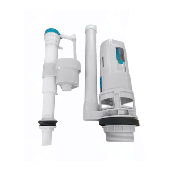
Parts Supplied:
Inlet Valve
1x
Please read these instructions carefully to avoid damage to the valves, and to ensure correct installation.
Do not use bleach or bleach based cleaning products in the cistern, as these will cause damage to the seals.
We cannot be held responsible or liable for any failure which results from the use of bleach based products.
Water temperature range +2C to +45C.
Water pressure 0.2 to 8 bar.
Inlet Valve Installation And Problem Solving
1: Inlet Valve scale and adjustment settings
A: Major water level adjustment
Installation Instruction for
Flush Valve
1x
Button
1x
Note:
The Inlet Valve should be adjusted for the particular cistern into
which it is being installed.
Please refer to the Adjustment Instruction on page 5 for the
X. Y settings.
The diagrams below show the detailed adjustment method.
1 - 7
Flush Cone
Bolt
2x
1x
B: Minor water level adjustment
F
Advertisement
Table of Contents

Summary of Contents for Burlington SP697
- Page 1 Installation Instruction for Dual Flush Cistern Fittings SP697 Parts Supplied: Flush Cone Inlet Valve Flush Valve Button Bolt Please read these instructions carefully to avoid damage to the valves, and to ensure correct installation. Do not use bleach or bleach based cleaning products in the cistern, as these will cause damage to the seals.
- Page 2 2: Inlet Valve installation 3: Filter cleaning (Please clean periodically) 4: Inlet Valve trouble shooting Problem Reason Solution Incorrect water level Incorrect adjustment. Adjust the Water level correctly as per page 1 & 2. Water supply is closed. Water supply is closed. Open the water supply Inlet Valve does not work The filter is blocked.
- Page 3 Flush Valve Installation And Problem Solving 1: Flush Valve scale and adjustment setting Note: The Flush Valve should be adjusted for the particular cistern into which it is being installed. Please refer to the Adjustment Instruction on page 6 for the full flush and half flush settings. The diagrams below show the detailed adjustment method.
- Page 4 Cistern and Flush Button Installation 1: Install Close Coupled Cistern To Pan 2: Connect the water supply to the cistern * Please ensure the flush cone is in position before installation. A thin bead of silicone should be applied to the flush cone and the inlet hole of pan if necessary. 3: Install The Flush Button Full flush Half Flush Button - Blue...
-
Page 5: Table Of Contents
Inlet Valve Adjustment Instructions Note: The above diagram is for reference only. In this example, X is set to 17 and Y is set to 3. The inlet valve can be adjusted to suit the particular cistern, please refer to below tables for the settings. -
Page 6: For 4.5L Full Flush And 2.6L Half Flush
Flush Valve Adjustment Instructions Note: The above diagram is for reference only. In this example, A is set to 6.5 and B is set to 2. The flush valve can be adjusted to suit the particular cistern, please refer to below tables for the settings. -
Page 7: Cistern Code
Recommended length of push rods Push rod The push rods can be cut off to suit the particular cistern, please refer to below table for the Z value. Cistern code Z (mm) CC.1036 CM0007 15.B.27353 15.B.27349 SPH002 MAR.006 7 - 7...
Need help?
Do you have a question about the SP697 and is the answer not in the manual?
Questions and answers