Table of Contents
Advertisement
Preface/Instruction .....................
1.1 Product Usage .............................. 2
1.2 Products Features ........................ 2
1.3 Operation Principle ....................... 2
1.4 Naming of the Model..................... 3
1.5 Main Components ......................... 4
2.
2.1 Preparation ................................... 6
2.2 Notice for Security ....................... 6
2.3 Operating Environment ................. 7
3.
3.1 Carton Packing ........................... 7
3.2 Wooden Case Packing ................. 7
4.
4.1 Prerequisite for Installation ........... 8
4.2 Environment for Installation .......... 8
4.3 Filling oil ........................................ 9
4.4 Connecting Electric ..................... 10
4.6 Connecting Vacuum System ...... 12
5.
5.1 Control Panel .............................. 13
5.2 Power on ..................................... 15
Vacuum pump ........................... 15
6.
6.1 Standard Operation .................... 17
Cycle ........................................... 18
6.3 Parameter Setting ....................... 20
6.4 Optimal Parameter ...................... 22
6.5 Packing Liquid Products ............. 22
6.6 Optimal Packing .......................... 23
7.
7.2 Vacuum Pump Maintenance ...... 24
Content
7.3 Special Oil for Vacuum Pump .......... 27
1
wire ................................................... 27
7.5 Replace Silicon Strip ........................ 29
7.6 Replace Sealing Ring ...................... 30
7.7 List of maintained components ........ 30
......................................................... 31
Device .............................................. 33
9.1 Parameter of A Series ..................... 34
9.2 Parameter of B Series ..................... 34
9.3 Parameter of C Series..................... 35
9.4 Parameter in Common .................... 36
10.1 Storage for short time ...................... 36
10.2 Storage for long time ....................... 36
10.3 Restart after storage ....................... 36
11.1 Diagram of Arch Vacuum Lid ........ 37
Chamber ........................................ 39
11.5 Diagram of Housing ........................ 41
Relay-controlling ............................. 42
Computer Panel-controlling ............ 44
............. 45
Advertisement
Table of Contents
Troubleshooting

Subscribe to Our Youtube Channel
Summary of Contents for HUALIAN HVC Series
-
Page 1: Table Of Contents
Content Preface/Instruction ..... 7.3 Special Oil for Vacuum Pump ..27 1. Product Description 7.4 Replace Teflon cloth and Flat Heating 1.1 Product Usage ......2 wire ........... 27 1.2 Products Features ......2 7.5 Replace Silicon Strip ......29 1.3 Operation Principle ....... -
Page 2: Preface/Instruction
Preface Thank you for your choice of our HVC Series Automatic Continuous Vacuum Packing Machine. The content of this instruction is as following: Product Description Notice for Security Carrying and Storage Installation and Commissioning Operating Guide ... -
Page 3: Product Description
1. Product Description 1.1 Usage and Application HVC series vacuum packaging machine possesses the advantages of superior function, easy operation, simple maintenance, wide application etc. It applies to the soft packing material such as composite film or aluminum-plastic composite film and so on. It can pack grain, food, fruit, seed, medicine, chemical product, electronic product, precision instrument and meter, rare expensive metal solid etc in liquid, powder or paste shape. -
Page 4: Naming Of The Model
B:flat vacuum chamber + arch lid C:flat vacuum chamber + thin lid D:vacuum chamber + flat lid Sealing Bar quantity (1pc or 2pcs or 4pcs) Model code S:double chamber T:table type F:floor type Sealing length(mm) (410;510;610) Vacuum machine with chamber Hualian vac - 3 -... -
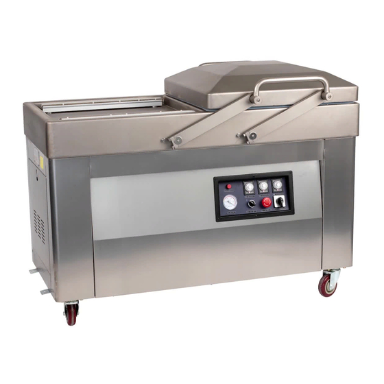
Page 5: Main Components
1.5 Main Components HVC-510S/2A(-G) Double-room Vacuum Packing Machine HVC-510S/2B(-G) Double-room Vacuum Packing Machine - 4 -... - Page 6 HVC-510S/2C Double-room Vacuum Packing Machine (Standard) Components Remarks Handle Vacuum chamber Arch lid/ultra-thin lid Connecting rod Lower sealing assembly Vacuum chamber Shallow/flat chamber Housing Control Panel Computer pane/Relay Caster - 5 -...
-
Page 7: Security
2. Security 2.1 Preparation This instruction is a detailed description of the carrying, storage, installation, startup, working condition, maintenance, troubles and repairing. It is recommended that the machine be installed by trained professional worker. Please do abide the maintenance instruction. ... -
Page 8: Operating Environment
TAKE CARE! Ignorance of this notice will lead to injury or property loss 2.3 Operating Environment The design of this product is running under normal temperature indoor. If the environment is in bad condition, such as corrosive atmosphere or temperature over 35℃ or less than 5℃,please contact the manufacturer or the supplier. -
Page 9: Installation
Note: Please fasten the attached belt or cord to the suitable position of the machine. Pay attention to the gravity of the machine. Make sure the cord is safely and tightly fastened to the machine. Hang the hanger to the tackle with safe locker. ... -
Page 10: Filling Oil
Make sure the Power meet the requirement. (see the name plate in the machine) Make sure the machine stands stably. Use foot plate to fix the machine after it is moved to a suitable position. The caster should leave the ground if there is any. ... -
Page 11: Connecting Electric
4.4 Connecting electric DANGEROUS! ELECTRIC SHOCK! Please make sure all the plugs have protective ground wire. TAKE CARE! Unmatched power will damage the machine. Please check the power parameter of the power referring to the label on the machine. Please abide the regulation of safe operation and the national protective measure of accident. -
Page 12: Connecting Gas-Filling System
Observe the fan of the vacuum pump motor if possible and determine the turning direction before the fan stops. If it is impossible to observe the turning direction, please listen to the sound of the motor. The vacuum pump running in reverse direction will beep. Look at the vacuum gauge as the vacuum pump in reverse direction can’t produce vacuum. -
Page 13: Connecting Vacuum System
4.6 Connecting Vacuum System (suitable for external vacuum pump) If you purchase the machine with built-in vacuum pump, it is unnecessary to follow this step. If you purchase the machine with external vacuum pump, please connect correctly the external vacuum pump. -
Page 14: Start And Operation
5. Start and Operation 5.1 Control Panel Control Panel for Relay-controlling Panel of HVC series (without gas-filling function) Name Instruction Show the state of power. The indicator will light when Power indicator the machine get electricity. Vacuum time Set the vacuummizing time, range from 0 to 60s. - Page 15 Heat-sealing voltage Option switch for heat-sealing voltage, separately high and low two options. Option switch Note:The cooling time relay of HVC series (with gas-filling function) is installed inside the electric box of the machine. Figure Name Remarks Shows the state of the functions during the working and the numbers will diminish.
-
Page 16: Power On
It is used to choose the temperature. The indicator on the right side of the monitor will flicker (high, Temperature Intermediate, low) as indication every time the button is select pressed. (Note: If these three indicators don’t light, the sealing can’t be acted.) Working The indicator lights (red) during the working period. - Page 17 The incorrect turning direction of the vacuum pump motor will damage the vacuum pump in even a short time. Please make sure the turning direction id correct before startup. For the machine adopting three phases power, there is a built-in vacuum pump or a power connector for connecting vacuum pump.
-
Page 18: Standard Operation And Parameter Setting
6. Standard Operation and Parameter Setting TAKE CARE! INJURED! Please operate according to this manual. Don’t remove the necessary guard cover or housing. TAKE CARE! UNHEALTHY! There is resin exist in the exhaust from the vacuum pump. Breathe the gas for long time is unhealthy. The machine should be used in a ventilating room. -
Page 19: Instruction Of Controlling Program's Cycle
Several bags can be placed simultaneously on the heating block or the silicon strip as long as the heating block or the strip is longer than the bags. Bags can’t be stacked. If the machine has more than one silicon strip, these strips can be used simultaneously. ... - Page 20 The cooling begins and cool the sealed bags as soon as the sealing is completed. The “ON” indicator of cooling time relay lights. Cooling The pointer of the vacuum gauge keeps stay. The “UP” indicator of cooling time relay lights when the cooling finishes.
-
Page 21: Parameter Setting
Rotate the time relay adjusting button to the scale needed. There are four adjustable time relays on the relay panel of HVC series (with gas-filling function), among which the vacuum time, sealing time and gas-filling time is installed on the control panel and the cooling time relay is in the electronic box inside the machine. - Page 22 The monitor shows “_ _” or “E Shows “_ _” or “E d” . Startup d” after startup. Choose the function by pressing Function Select button. Press once to choose next function. When one function is selected, the Shows the set value of corresponding indicator lights the selected function.
-
Page 23: Optimal Parameter
Shows “_ _” or “E d” . When the Temperature Select button choose one temperature level, the corresponding indicator will light (red). The sealing won’t be acted if the three indicator all light out. 6.4 Optimal parameter The vacuumizing time should be determined by the quantity and the size of the materials in the vacuum chamber. -
Page 24: Optimal Packing
6.6 Optimal packing Employ good quality vacuum bag in correct style. Leave enough space on the bag mouth, at least 30mm. Place the vacuum bag neat on the heating block or the silicon strip. If the bags are much lower than the heating block or the silicon strip, please insert proper base plates (if any). -
Page 25: Standard Maintenance Schedule
7.1 Standard Maintenance Schedule Cycle Maintenance Clean the vacuum chamber, vacuum lid and housing with wet cloth and remove the foreign materials attached on the heating block. Daily The cleaner should be solvent-free. Don’t use high pressure cleaner. ... - Page 26 There is no vacuum pump oil of the newly delivered machine. Please fill the oil for its first use. Check the color of the vacuum pump oil. The vacuum pump oil is bright and clear without any foam or muddle. If there are white materials after the precipitation, it indicates there are foreign materials in the oil.
- Page 27 The newly delivered machine should be filled with oil. Fill the oil after the oil-drain or when the oil level descends. Unscrew the oil-filling plug with wrench in correct size. Fill the machine with appropriate special oil for vacuum pump. Please refer to the Special Oil ...
-
Page 28: Special Oil For Vacuum Pump
Reinstall the spring and the filter cover. Install the back cover to the housing. Dispose the wasted oil mist filter following the environmental laws. 7.3 Special oil for vacuum pump The temperature of the working environment is important for the choice of the oil type. The following table lists the relationship among the working temperature, oil quantity and oil type. - Page 29 A:Vacuum lid B:Sealing ring C:Airbag seat D:Airbag E : Heating plate seat F : Heating plate assembly 1:Binding post 2:Locking screw 3:Upper gasket of heating tape 4:Lower gasket of heating strip 5:Tension spring 6:Flat heating wire 7:Teflon cloth 8:Liner panel 9:Clamp plate for Teflon cloth 10:Fixed Block for heating strip 11:Aluminum profile...
-
Page 30: Replace Silicon Strip
Remove the heating plate. Remove the pressure tape for pressing Teflon cloth. Remove the Teflon cloth on the heating plate. If it is for replacing only the Teflon cloth, wipe the grease away with a clean cloth, then stick the new Teflon cloth to the heating plate. -
Page 31: Replace Sealing Ring
Note: One side of the silicon strip is reticulate pattern, and the other is reticulate pattern with fixed holes. It can be installed with character, which is used to print label. Choose the side as your needs. 7.6 Replace Sealing Ring The sealing ring keeps the vacuum chamber sealed during its working, which is essential to get the needed vacuum level. -
Page 32: Trouble Shooting
8. Trouble shooting 8.1 Trouble shooting of the machine body Troubles Reasons Solutions No connection of the power Put the power plug to the power supply. socket. machine doesn’t work and The fuse of the main circuit burns Replace fuse (same the control panel out. -
Page 33: Trouble Shooting Of Vacuum Pump
gas-filling (if any) Air tank closed. Open the valve. Check whether the pressure gauge or the secondary pressure is set as 1 atmospheric pressure Incorrect setting of the filling (1-ATM). pressure. Warning! The compound gas can’t be higher than 1-ATM anytime. -
Page 34: Trouble Shooting Of The Sealing Device
silicon rectifier diode breakdown Replace Coil burnout Replace The lifting part of the Armature iron has Replace contaminants. Blocked spring caused by rust or Replace breakage Too low voltage Check the power voltage 8.4 Trouble shooting of the sealing device Troubles Reasons Solutions... -
Page 35: Technical Parameter
9. Technical parameter 9.1 Technical parameter of A series double-room Vacuum packing machine Size of vacuum Specification of Gas- Sealing Specification of Model External dimension Power chamber vacuum pump filling specification Sealing transformer HVC-410S/2A 510×500mm 410×10mm 500W 1070X720X940 Single phase 220V/50Hz √... -
Page 36: Parameter Of C Series
9.3 Technical parameter of C series double-room Vacuum packing machine Size of vacuum Specification of Gas- Sealing Specification of Model External dimension Power chamber vacuum pump filling specification Sealing transformer 610×550mm 510×10mm HVC-510S/2C 600W 1270×720×910 Depth 45mm 610×630mm 510×10mm 1500W HVC-510S/4C 1270×805×910 Depth 45mm... -
Page 37: Parameter In Common
9.4 Technical Parameter in common Min absolute pressure in the vacuum 1Kpa chamber 5~30℃ Temperature of standard environment The max deviation from the required one should Requirement for power be within+10% Gas-filling connector (if any) Gas-tank connector in max pressure 1 standard atmosphere Specification of Control transformer 100W... -
Page 38: Diagrams
11. Diagram 11.1 Diagram of Arch Vacuum Lid (suitable for A, B series) Diagram(1) Name Remarks Vacuum lid Arch lid O type ring Bearing Handle Small axle Washers for axle Handle holder External connector of airbag Connector of through-tube 1-10 O type ring 1-11 Airbag assembly... -
Page 39: Diagram Of Ultra-Thin Vacuum Lid
11.2 Diagram of Ultra-thin Vacuum Lid (suitable for C series) Diagram(2) Name Remarks Vacuum lid Arch lid O type ring Bearing Handle Small axle Washers for axle Handle holder External connector of airbag Connector of through-tube 2-10 O type ring 2-11 Airbag assembly 2-12... -
Page 40: Diagram Of Shallow Vacuum Chamber
11.3 Diagram of Shallow Vacuum Chamber (suitable for A series) (3) Diagram Name Remarks connecting rod Press tape Vacuum chamber deep chamber Silicon strip Silicon strip seat Silicon strip Sealing ring Stopper plug Gas-filling pipe connector (optional) Long axle 3-10 Travel switch block 3-11 Tension spring shaft... -
Page 41: Diagram Of Flat Vacuum Chamber
11.4 Diagram of Flat Vacuum Chamber (suitable for B, C series) Diagram(4) Name Remarks connecting rod Press tape Vacuum chamber Shallow chamber Silicon strip Silicon strip seat Silicon strip Sealing ring Stopper plug Gas-filling pipe connector (optional) Long axle 4-10 Travel switch block 4-11 Tension spring shaft... -
Page 42: Diagram Of Housing
11.5 Diagram of Housing (take as HVC-510S/2A with relay-controlling an example) Diagram(5) Name Remarks Left door of the housing Vacuum pump (XDZ-020 sliding-vane rotary) Sealing transformer Control transformer Electric box Trunking Rear cover assembly of housing AC contactor Electrical switch 5-10 Wiring terminal 5-11... -
Page 43: Electric Schematic Diagram
12. Electric Schematic Diagram Electric Schematic Diagram of Relay-controlling 12.1 Single phase without gas-filling function Single phase with gas-filling function ... - Page 44 Three phases without gas-filling function Three phases with gas-filling function ...
-
Page 45: Electric Schematic Diagram Of Computer Panel-Controlling
Electric Schematic Diagram of Computer Panel-controlling 12.2... -
Page 46: Diagram Of Gas Circuit
13. Diagram of Gas circuit (take A series as an example)
Need help?
Do you have a question about the HVC Series and is the answer not in the manual?
Questions and answers
Низкое качество шва плохой прижим нагревателя к основанию
Common issues with seam quality and heater pressure in the HUALIAN HVC Series include:
1. No heating – Caused by incorrect heating temperature selection. Solution: Choose the proper heating temperature.
2. Sealing failure – May occur if sealing is done before reaching the proper vacuum level. Solution: Ensure the vacuum level is higher than 0.6 MPa before sealing.
3. Too long or too short sealing time – This affects seam quality. Solution: Adjust the sealing time appropriately.
4. Flat heating wire damage – Can lead to poor sealing. Solution: Replace the heating wire.
This answer is automatically generated