Table of Contents
Advertisement
Advertisement
Table of Contents

Related Manuals for SMAC CBC-EIP


Summary of Contents for SMAC CBC-EIP
- Page 1 CBC-EIP USER MANUAL Version 1.0.5, January 2020...
- Page 2 The contents of this user manual are intended to be as accurate as possible, but may be subject to change without prior notification. SMAC shall not be liable for any damages that may arise as a consequence of the use of information presented in this user manual.
-
Page 3: Table Of Contents
SMAC Motor off ........................30 3.10 Motor Quick Stop ........................31 Step by step software setup ......................32 Allen Bradley PLC with SMAC CBC-EIP drives .................32 Any PLC with SMAC CBC-EIP drives ..................38 Firmware update and PDO parameter setup .................39 4.3.1 Regular update ......................40 4.3.2... - Page 4 4.4.2 Error: Invalid Input/Output size (Code 16#0127) ............46 4.4.3 No ethernet data transfer between PLC and CBC-EIP drives ........46 4.4.4 No ethernet communication ...................46...
-
Page 5: Introduction
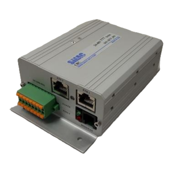
Introduction The CBC-EIP is an Ethernet/IP servo drive with specifications as presented in Table 1. Physically, the CBC- EIP circuit board can be situated inside a housing as shown in Figure 1. An example of Ethernet/IP network architecture involving CBC-EIP is shown in Figure 2. - Page 6 Figure 1. CBC-EIP. Ethernet/IP master device, e.g. PLC CBC-EIPs Actuators Figure 2. Typical Ethernet/IP network architecture with CBC-EIPs.
-
Page 7: Setup Guide
Setup guide 2.1 Hardware 2.1.1 Power/signal/communication connectors Figure 3 shows the connectors and status LED indication of the CBC-EIP. Further details about these connectors are presented in Table 2. ETH 1 ETH 2 I/O AND STO 1 2 3 4 5 6 7 8... -
Page 8: I/O And Sto Electrical Schematics
Table 2. Details on connectors in Figure 3 CONNECTOR PIN DEFINITION POWER (Terminal block header, 5 mm pitch) 1: Ground (DC power Return) 2: +24VDC/+48VDC supply 3: Actuator winding phase U 4: Actuator winding phase V 5: Actuator winding phase W 6: Ground ENCODER (Standard D-SUB 15 pin, female) 1: A+... - Page 9 For the purpose of interfacing I/Os and STOs between the CBC-EIP and external devices, electrical schematics are given in Figures 4 – 7. +3.3 V 10KΩ Digital input 1 (5VDC – 24 VDC) Pin 1 To CBC’s microcontroller 10KΩ Digital input 2 (5VDC –...
-
Page 10: Disabling The Sto (Optional)
(Failure to do this will affect ethernet connection) The CBC-EIP includes a Safe Torque Off (STO) circuit. The STO is a safety system that prevents motor torque in an emergency event while CBC-EIP remains connected to the power supply. When STO is... -
Page 11: Fully Independent Sto Channels
Figure 9. Schematics of STO circuit. The CBC-EIP STO has been designed to be compliant with Safety Integrity Level 3 (SIL 3) according to IEC 61800-5-2. In order to fulfil the requirements, the STO reliability has been increased by means of the following characteristics: •... -
Page 12: Sto Abnormal Operation
The objective of the STO_FB is to allow external diagnostics of the STO circuit, allowing an increase of the system reliability. A common-practice in the diagnostics is to delay the stop of the power stage from the deactivation of the STO_FB and from the deactivation of the STO inputs. This way, short pulses can be applied for testing the STO circuit without stopping the system operation. - Page 13 The following table shows a summary of the STO performance. Mode Status STO1 STO2 Power STO_FB Drive function input input stage state Normal Disabled Drive cannot start or ACTIVE operation provide power to the (No torque to motor. STO trip reported the motor) to the DSP and to STO_FB.
-
Page 14: Software
2.2 Software Remark: in order to work with the software part of CBC-EIP, the user is expected to be familiar with SMAC’s LCC Control Center software and the embedded motion control library (EMCL) manual. 2.2.1 Basic drive configuration of CBC-EIP Essentially, the CBC-EIP consists of an improved version of SMAC CBC controller and an Ethernet/IP hardware/software interface. -
Page 15: Modification Of Ip (Internet Protocol) Settings
Ethernet/IP objects such as Identity, TCP/IP Interface and Ethernet Link, as well as all the objects belonging to the drive functionalities of CBC-EIP, as can be found from object dictionary list in the embedded motion control library manual (https://www.smac-... -
Page 16: Implicit (Io) Messaging
Example: to obtain the value of object Max torque through Explicit messaging → service code: 0x0E, Class: 0x64, Instance: 0x6072, Attribute: 0x00 2.2.4 Implicit (IO) messaging The CBC-EIP supports a simultaneous class 1 connection type of exclusive owner, with the specifications: •... -
Page 17: Add-On Instructions (Aoi) For Studio5000/Rslogix5000 Plc Software
Add-On Instructions (AOI) for STUDIO5000/RSLogix5000 PLC software 3.1 Position move This AOI is used to perform a linear or rotary position move. Position Move AOI: input and output parameters Parameter Unit Description Busy bit This bit is active when the AOI is being executed, until Done bit is active. - Page 18 Ladder logic example:...
-
Page 19: Softland Move
3.2 Softland Move This AOI is used to perform SMAC’s softland move. Softland Move AOI: input and output parameters Parameter Unit Description Done bit This bit is active when the target position has been reached. Soft landed Position Counts Position of the actuator after softland action... - Page 20 Mapping between softland move AOI parameters and PLC IO data assemblies Byte address Description Input: 2 - 5 46: Softland move in progress 56: Softland is complete Input: 6 - 9 Softlanded Position Output: 0 - 3 Macro value of softland move (Table 3) Output: 4 Direction Output: 5...
-
Page 21: Homing Move
3.3 Homing Move This AOI is used to perform Homing move. Homing Move AOI: input and output parameters Parameter Unit Description This bit is active when the homing is complete Homing done and actuator is at 0 position. Homing busy This bit is active when the AOI is being executed, until the Done bit is active This bit specifies homing methods... - Page 22 Mapping between homing move AOI parameters and PLC IO data assemblies Byte address Description Input: 2 - 5 41: Homing move in progress 51: Homing move is complete Output: 0 - 3 Macro value of Homing move (Table 3) Output: 4 - 5 Direction: 1: negative mech.
-
Page 23: Velocity Move
3.4 Velocity move This AOI is used to perform velocity move. Velocity move AOI: input and output parameters Parameter Unit Description This bit is active when the AOI is being Busy executed, until the Done bit is active Target Velocity Counts/s Final velocity the actuator is intended to achieve during the motion profile... -
Page 24: Force Move
3.5 Force Move This AOI is used to perform force move. Force Move AOI: input and output parameters Parameter Unit Description Busy This bit is active when the AOI is being executed, until the Done bit is active ‰ of motor Force of the actuator at the moment (Current Actual force rated current... -
Page 25: Smac Fault Status
Ladder logic example: 3.6.1 Performing fault reset Faults in the CBC-EIP can be reset only by manipulating the control word, which is accessible through explicit messaging. In the PLC, this can be done through the message instruction “MSG” available in RSLogix5000/Studio5000 software. - Page 26 Set the (2) source length as 2. (3) Set the data type to DINT and (4) style as decimal. Set the (5) external access to Read/Write. Click Create. c. Go to the communication tab and specify the Ethernet module (SMAC CBC I-3/6-I) from the browse button. Check the connected and cache connections check box.
- Page 27 d. Go to the controller Tags and look for the newly created tag from MSG instruction (In this example tag name is RESET). Enter the value 128. Make sure that the value entered is reset back to 0 and then to 128 every time to provide data change. Ladder logic example:...
-
Page 28: Smac Motor Halt
3.7 SMAC Motor halt This AOI is used to halt the motor only after Rotary Softland operation. The motor will hold position and remain in on state when at halt. Note: Do not use this during any of the other motion sequence. -
Page 29: Smac Motor On
3.8 SMAC Motor on This AOI is used to turn the actuator on. The actuator will hold position and the difference between Motor halt and motor on can be found from the Embedded Motion Controller Library manual. SMAC Motor On AOI... -
Page 30: Smac Motor Off
3.9 SMAC Motor off Motor off can be done by using MSG instruction using a explicit messaging format. Use the following 1. Service code, 2. Class number, 3. Instance value, 4. Service type as Set Attribute Single, 5. Attribute as 0. Create a tag with any name Eg. RT_MF_BIT with length 2 byte and enter a value 7 (This is the... -
Page 31: Motor Quick Stop
2 is used to enable quick stop. For further information on quick stop refer to Embedded Motion controller library document https://www.smac-mca.com/lcc-single-axis- brushless-controller-p-125.html?cPath=1_10. Page number 43 -47 will provide more information on Quick stop at bit level representation. To verify, if the quick stop has been completed, check the statusword object for bit 5. It should be 0. -
Page 32: Step By Step Software Setup
Step 3: Copy and paste the System Macro V2.mlm file into C:\Program Files(x86)\SMAC\LCC Control Centre\System Macro V2.mlm Step 4: If firmware update is performed on the CBC-EIP drive, move to section 4.3 and then come back to Step 5. If not, then proceed to step 5. - Page 33 Image 2 Image 3...
- Page 34 Image 4 Image 5...
- Page 35 Image 6 Image 7 Step 11: Import all the Add-On-Instruction (AOI) files. Incase if you face errors during Import, refer to software troubleshooting section 4.4.
- Page 36 Image 8 Image 9 Image 10 Step 12: Create an ethernet module and make sure there are no errors, when the controller is online. In-case of any errors look into software troubleshooting section 4.4.
- Page 37 Image 11 Image 12...
-
Page 38: Any Plc With Smac Cbc-Eip Drives
Step 3: Copy and paste the System Macro V2.mlm file into C:\Program Files(x86)\SMAC\LCC Control Centre\System Macro V2.mlm Step 4: If firmware update is performed on the CBC-EIP drive, move to section 4.3 and then come back to Step 5. If not, then proceed to step 5. -
Page 39: Firmware Update And Pdo Parameter Setup
Upgrading the firmware can be done in two different ways. Regular update or Forced update. Forced update is only recommended in cases where Regular update fails or when SMAC specifically recommends using it. Firmware Loader requires that your Servo Drive UART configuration is set to 115200bps (default). -
Page 40: Regular Update
Do not disconnect power from the controller(s) while the firmware is loading. Doing so can cause severe damage and you will have to send the unit back to SMAC for repair. All parameters on the controller will be reset to their default values when the new firmware is loaded. -
Page 41: Forced Update
4.3.3 PDO parameter setup Every time the firmware is updated, the PDO mapping file has to be downloaded into the CBC-EIP controller. If this step is skipped, then implicit messaging will not occur. Step 1: Download the octave software from https://www.gnu.org/software/octave/download.htm... - Page 42 Step 3: Once the file is opened, change the COM Port number if needed at two location as shown below Step 4: Once the COM port is changed, select all the lines of code and click Run> Run selection. Make sure all the other serial communication software are closed. Step 5: verify if all the code has been downloaded without error using Command window from bottom Image 1.
- Page 43 Image 1: Good result Image 2: Bad result...
- Page 44 Step 6 : To verify if the PDO has been configured properly, use Termite software Open the termite and go to https://www.compuphase.com/software_termite.htm Settings> and change the settings as shown below. Then type 0x20 R 0x1A00 and the reply will be 0x20 W 0x1A00 8. Type 0x20 R 0x1600 and the reply will be ox20 W0x1600 6.
-
Page 45: Common Software Troubleshooting
4.4 Common software troubleshooting 4.4.1 IP address alterations IP address of the CBC-EIP drives can be altered by different methods as discussed in section 2.2.2. If the user forgets the IP address of the drive and wanted to identify the drive, any DHCP software can be used to automatically scan the drive in ethernet network. - Page 46 2.2.1 and 4.1 for more information on installing the file properly. 4.4.4 No ethernet communication When the communication to the CBC-EIP controller is lost, it cannot be identified by any health status led. But it can be identified either in the PLC module or through the...
Need help?
Do you have a question about the CBC-EIP and is the answer not in the manual?
Questions and answers