Advertisement
Quick Links
Bedienungs‐ und Wartungsanleitung
Operation and Maintenance Manual
TDP072d+e.doc
Perrot REGNERBAU CALW GmbH Industriestraße 19‐29 / D‐75382 Althengstett / Germany
Telefon : 0049‐7051‐162‐0 / Fax : 0049‐7051‐162–133
E‐mail: p errot@perrot.de / E‐mail Konstruktion : technik@perrot.de
PERROT
Steuergerät Water Control+ SC
Controller Water Control+ SC
Rev. 07.07.2015
Seite‐Page 1 / 64
Advertisement

Summary of Contents for Perrot Water Control+ SC
- Page 1 Bedienungs‐ und Wartungsanleitung Operation and Maintenance Manual PERROT Steuergerät Water Control+ SC Controller Water Control+ SC TDP072d+e.doc Rev. 07.07.2015 Seite‐Page 1 / 64 Perrot REGNERBAU CALW GmbH Industriestraße 19‐29 / D‐75382 Althengstett / Germany Telefon : 0049‐7051‐162‐0 / Fax : 0049‐7051‐162–133 E‐mail: p errot@perrot.de / E‐mail Konstruktion : technik@perrot.de ...
-
Page 2: Table Of Contents
1. General We assume that you are familiar with the general issues of irrigation. This manual is therefore brief and contains only information, which needs to be at hand during system operation. Warranty claims may only be made if the controller has been operated according to instructions set forth in this manual and if the fault occurs during the warranty period. 1.1. Application The Water Control can be used for programmed opening and closing of 24V/50Hz valves. The valves are predominantly used in the irrigation systems. Operating temperature: 0°C to 50°C Storing temperature: ‐20°C to 50° 1.2 Warranty Information Regnerbau Calw GmbH warrants to its trade customers that its products will be free from original defects in material and/or workmanship. The provided product is used for irrigation, in accordance with recommendations as specified by the manufacturer, for the duration of the warranty period specified hereinafter. The warranty does not cover controller faults caused by act of God (storms, floods, etc.). TDP072d+e.doc Rev. 07.07.2015 Seite‐Page 32 / 64 Perrot REGNERBAU CALW GmbH Industriestraße 19‐29 / D‐75382 Althengstett / Germany Telefon : 0049‐7051‐162‐0 / Fax : 0049‐7051‐162–133 E‐mail: p errot@perrot.de / E‐mail Konstruktion : technik@perrot.de ... -
Page 3: Safety
2. Safety This operation & safety manual contains basic instructions for installation, operation, maintenance and repair of the controller. It is absolutely necessary that the professional installation technician and qualified staff/operator study this manual thoroughly prior to initiating the controller installation and commissioning. Please follow both the general safety instructions specified in this chapter, and the particular safety warnings pointed out in other chapters. 2.1. Marking of Instructions in the Operating Manual Safety instructions, non‐compliance with which could lead to risking people's health are marked with the "danger" symbol: "Warning" is printed next to instructions where non‐compliance may represent a risk to the controller and/or its operation. When the controller is plugged into the mains, its transformer is powered up. Touching it may result in a life‐threatening electric shock! 2.2. Risk in Case of Ignoring the Safety Instructions Not respecting the safety instructions may result in serious injuries, damage to the environment and/or the controller. Not respecting the safety instructions may waive liability for all and any claims for covering damage. TDP072d+e.doc Rev. 07.07.2015 Seite‐Page 33 / 64 Perrot REGNERBAU CALW GmbH Industriestraße 19‐29 / D‐75382 Althengstett / Germany Telefon : 0049‐7051‐162‐0 / Fax : 0049‐7051‐162–133 E‐mail: p errot@perrot.de / E‐mail Konstruktion : technik@perrot.de ... -
Page 4: Description
Station connections – variable from 4 to 24 stations 2 to 12 station connections when using the Sector Scout function 24VAC master‐valve or a pump relay Potential free opener contact (rain sensor) Permanent 24VAC 3.4 Indicators and functions LC display 70x40mm Displays time and status bar 5 multi‐function keys 3.5 Dimensions and miscellaneous Plastic housing dimensions: length: 350mm; width: 270mm; height: 110mm 8 field cable connection lugs with safety snag feature Programmable station delay times (0‐99 sec.) ensure proper pressure conditions when valves open and close Pump after‐run time (0‐15 sec.) for pressure stabilization TDP072d+e.doc Rev. 07.07.2015 Seite‐Page 34 / 64 Perrot REGNERBAU CALW GmbH Industriestraße 19‐29 / D‐75382 Althengstett / Germany Telefon : 0049‐7051‐162‐0 / Fax : 0049‐7051‐162–133 E‐mail: p errot@perrot.de / E‐mail Konstruktion : technik@perrot.de ... -
Page 5: Installation
4. Installation 4.1 Wall mounting Choose a dry location protected from direct sunlight for the installation of the controller Remove the front cover (see chapter 5) and fix the back cover of the housing to the wall with three screws (included in the package). Mounting hole Please note that the controller may touch the wall only at the points with screw holes. Do not plug the controller into the mains until it is mounted on the wall, all valves are connected and the front cover is fixed back in place. TDP072d+e.doc Rev. 07.07.2015 Seite‐Page 35 / 64 Perrot REGNERBAU CALW GmbH Industriestraße 19‐29 / D‐75382 Althengstett / Germany Telefon : 0049‐7051‐162‐0 / Fax : 0049‐7051‐162–133 E‐mail: p errot@perrot.de / E‐mail Konstruktion : technik@perrot.de ... - Page 6 4.2 Connect Controller and Valves Wiring diagram for rain sensor for external start with key switch for short time clock TDP072d+e.doc Rev. 07.07.2015 Seite‐Page 36 / 64 Perrot REGNERBAU CALW GmbH Industriestraße 19‐29 / D‐75382 Althengstett / Germany Telefon : 0049‐7051‐162‐0 / Fax : 0049‐7051‐162–133 E‐mail: p errot@perrot.de / E‐mail Konstruktion : technik@perrot.de ...
- Page 7 WARNING If both, stations with Sector Scout (VP3SC) and stations with valves only are connected to the same controller, the stations with Sector Scout need to be connected one by one starting with module 1. The valves can then be connected to the remaining modules regardless of their order. TDP072d+e.doc Rev. 07.07.2015 Seite‐Page 37 / 64 Perrot REGNERBAU CALW GmbH Industriestraße 19‐29 / D‐75382 Althengstett / Germany Telefon : 0049‐7051‐162‐0 / Fax : 0049‐7051‐162–133 E‐mail: p errot@perrot.de / E‐mail Konstruktion : technik@perrot.de ...
- Page 8 Connect rain sensor as per wiring diagram. Turn the main dial to “Setup” and set appropriate type of rain sensor (opener or closer). Connect key switch for external program start (Order‐no.: SB49165) Connect key switch as per wiring diagram. We recommend to use: Jung key switch 833.18W; WG 800 IP44 contact (opener/closer) and Jung profile cylinder for key switch UP3 key (closer), 3051938 Jung 28 (Granzow order no.) Turn the main dial to “Setup” and select key switch (page 16). Connect short time clock (external switch) Valves with short time operation may be activated directly on site, using the permanent 24VAC contact (see wiring diagram). This circuit is commonly used on tennis courts in order to eliminate dust by short‐term irrigation. Note: T he master valve will not start when activating the valves by means of a short time clock. This will require special cabling. Please contact the manufacturer. TDP072d+e.doc Rev. 07.07.2015 Seite‐Page 38 / 64 Perrot REGNERBAU CALW GmbH Industriestraße 19‐29 / D‐75382 Althengstett / Germany Telefon : 0049‐7051‐162‐0 / Fax : 0049‐7051‐162–133 E‐mail: p errot@perrot.de / E‐mail Konstruktion : technik@perrot.de ...
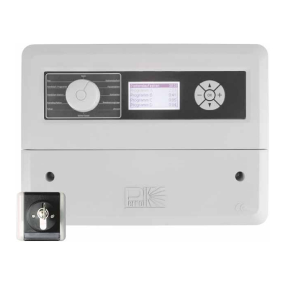
- Page 9 5. Initial Startup Controller Display control panel Menu guidance via rotary dial Fuse Safety snag feature for Cable connection lugs cables fixing screw for Output module output module TDP072d+e.doc Rev. 07.07.2015 Seite‐Page 39 / 64 Perrot REGNERBAU CALW GmbH Industriestraße 19‐29 / D‐75382 Althengstett / Germany Telefon : 0049‐7051‐162‐0 / Fax : 0049‐7051‐162–133 E‐mail: p errot@perrot.de / E‐mail Konstruktion : technik@perrot.de ...
- Page 10 Display When the controller is powered on for the first time, the following startup screen is displayed: Current menu and status bar Current time Work area Programming Menu Selection You can select menu 1 to 12 using the rotary dial. The currently selected menu is indicated in the display header line. TDP072d+e.doc Rev. 07.07.2015 Seite‐Page 40 / 64 Perrot REGNERBAU CALW GmbH Industriestraße 19‐29 / D‐75382 Althengstett / Germany Telefon : 0049‐7051‐162‐0 / Fax : 0049‐7051‐162–133 E‐mail: p errot@perrot.de / E‐mail Konstruktion : technik@perrot.de ...
- Page 11 : decreases the selected value : scrolls up through menu : scrolls down through menu Set current date / time 5. To access the menu, turn the main dial to Time 6. To make a selection use or Taste. The selected menu function will start flashing. 7. Use or to set current time and day. 8. Press OK to save the changes made before leaving the menu. Note: Date and time settings will be saved for at least one year in case of power outages. TDP072d+e.doc Rev. 07.07.2015 Seite‐Page 41 / 64 Perrot REGNERBAU CALW GmbH Industriestraße 19‐29 / D‐75382 Althengstett / Germany Telefon : 0049‐7051‐162‐0 / Fax : 0049‐7051‐162–133 E‐mail: p errot@perrot.de / E‐mail Konstruktion : technik@perrot.de ...
- Page 12 Note: If the controller has 2 output modules, you can program only 8 stations (2 modules × 4 stations). Set Station delay time 5. To access the menu, turn the main dial to Station Delay Time. 6. The selected menu function will start flashing. Press the and buttons to navigate from station run times to station delay time. 7. Set the required station delay time using and . 8. Save values entered by leaving the menu but press OK before leaving the menu. The station delay time can be set from 0‐99 seconds. Note: Station delay time: This feature delays the start of the next sequential station in a program after the previous station completes. Pump after‐run time: To avoid pump low pressure trips the pump may continue running for a certain amount of time after the last sprinkler closes. TDP072d+e.doc Rev. 07.07.2015 Seite‐Page 42 / 64 Perrot REGNERBAU CALW GmbH Industriestraße 19‐29 / D‐75382 Althengstett / Germany Telefon : 0049‐7051‐162‐0 / Fax : 0049‐7051‐162–133 E‐mail: p errot@perrot.de / E‐mail Konstruktion : technik@perrot.de ...
- Page 13 Line = no irrigation Day (e.g. SA) = irrigation activated 13. To activate a particular day use . The display will automatically advance to the next day. Repeat steps 4 and 5 until all watering days for the whole week have been set and press to confirm. 14. Repeat steps 3 to 6 for other start times of the program. Repeat steps 2 to 6 for other irrigation programs. Note: To make sure that the irrigation programs do not overlap, turn the dial to AUTO If the display shows ERROR it will also show which programs do overlap. Please edit start times and watering days accordingly and try again. TDP072d+e.doc Rev. 07.07.2015 Seite‐Page 43 / 64 Perrot REGNERBAU CALW GmbH Industriestraße 19‐29 / D‐75382 Althengstett / Germany Telefon : 0049‐7051‐162‐0 / Fax : 0049‐7051‐162–133 E‐mail: p errot@perrot.de / E‐mail Konstruktion : technik@perrot.de ...
- Page 14 Manual Start of an Irrigation Program 6. To access the menu, turn the main dial to Start Program. 7. Press the and buttons to make a selection. The program selected will be flashing. 8. Press to start the irrigation program. 9. The screen will display the time left of a program and of a station in minutes indicated by blocks. 10. One more press will turn it off. Note: You can start a station or an irrigation program regardless of the rain sensor status. If the dial is turned to AUTO during operation, it will continue in AUTO mode after the program has finished. TDP072d+e.doc Rev. 07.07.2015 Seite‐Page 44 / 64 Perrot REGNERBAU CALW GmbH Industriestraße 19‐29 / D‐75382 Althengstett / Germany Telefon : 0049‐7051‐162‐0 / Fax : 0049‐7051‐162–133 E‐mail: p errot@perrot.de / E‐mail Konstruktion : technik@perrot.de ...
- Page 15 Note: This menu runs all irrigation programs which have one or more pre‐set start times and watering days. If the rain sensor is enabled, “rain stop” and the time when the rain sensor was activated will be displayed on the screen. This mode will suspend all active irrigation programs and scheduled programs will be prevented from starting. If an irrigation program is running, the screen shows: “program active”. Here you can see the progress statistic, start and stop times of the entire program as well as of individual active stations The , and buttons have no function in this menu. TDP072d+e.doc Rev. 07.07.2015 Seite‐Page 45 / 64 Perrot REGNERBAU CALW GmbH Industriestraße 19‐29 / D‐75382 Althengstett / Germany Telefon : 0049‐7051‐162‐0 / Fax : 0049‐7051‐162–133 E‐mail: p errot@perrot.de / E‐mail Konstruktion : technik@perrot.de ...
- Page 16 Press and to make a selection and confirm with A2: Key Switch Please make sure to connect key switch as per wiring diagram 4.2. Select “Rain sensor” by using the and buttons. Use and to navigate to “Key” and press to confirm. Note: Turning the key switch will immediately start Prg.A BUT only if the main dial is not turned to “SYSTEM OFF” External program starts can be stopped by turning the key switch one more time. TDP072d+e.doc Rev. 07.07.2015 Seite‐Page 46 / 64 Perrot REGNERBAU CALW GmbH Industriestraße 19‐29 / D‐75382 Althengstett / Germany Telefon : 0049‐7051‐162‐0 / Fax : 0049‐7051‐162–133 E‐mail: p errot@perrot.de / E‐mail Konstruktion : technik@perrot.de ...
- Page 17 CZ = Czech PL = Polish RU = Russian NL = Dutch DK = Danish FR = French C: Programs Factory setting = 3 irrigation programs (A/B/C) which can be expanded to 4 or 5 (A/B/C/D/E). Press and to select “Programs”. Press and to increase/decrease the number of programs (1 to 5) and press before leaving the menu. D: Information This function is only for information purposes about the software and hardware used and is therefore only of minor importance to the customer. TDP072d+e.doc Rev. 07.07.2015 Seite‐Page 47 / 64 Perrot REGNERBAU CALW GmbH Industriestraße 19‐29 / D‐75382 Althengstett / Germany Telefon : 0049‐7051‐162‐0 / Fax : 0049‐7051‐162–133 E‐mail: p errot@perrot.de / E‐mail Konstruktion : technik@perrot.de ...
- Page 18 Sensor time Cycle time Before commissioning a system with VP3 Sector Scout sprinklers we recommend to proceed as described below. Sensor Setup The following functions can be edited in this menu. Press and to select the function you want, when it starts flashing press to confirm. Factory setting = only solenoids are connected, i.e. 4 solenoids (stations) per module can be connected. TDP072d+e.doc Rev. 07.07.2015 Seite‐Page 48 / 64 Perrot REGNERBAU CALW GmbH Industriestraße 19‐29 / D‐75382 Althengstett / Germany Telefon : 0049‐7051‐162‐0 / Fax : 0049‐7051‐162–133 E‐mail: p errot@perrot.de / E‐mail Konstruktion : technik@perrot.de ...
- Page 19 Please proceed as follows: Press and to select „Module setup“ and press to confirm. Press and to select a station where a VP3 with Sector Scout is supposed to be connected. Use to set the selected station to „SC output“. Warning If both, stations with Sector Scout (VP3SC) and stations with valves only, are connected to the same controller, all stations with Sector Scout have to be connected in consecutive order starting from module 1. The valves (no Sector Scout) can then be connected to the remaining modules regardless of their order. press to confirm entry. To get back to the „Sector Scout“ menu, press „previous menu“. TDP072d+e.doc Rev. 07.07.2015 Seite‐Page 49 / 64 Perrot REGNERBAU CALW GmbH Industriestraße 19‐29 / D‐75382 Althengstett / Germany Telefon : 0049‐7051‐162‐0 / Fax : 0049‐7051‐162–133 E‐mail: p errot@perrot.de / E‐mail Konstruktion : technik@perrot.de ...
- Page 20 Use the and keys to select „sensor position“ and press to confirm. The display will now show all stations with Sector Scout. The black blocks along the bar show the progress of each station with Sector Scout. Please see page 25 “sensor position bar” for detailed explanation of each signal. Use the and keys to select a station Press to enter the selection menu which will offer you the following options: Cancel „Cancel“ will bring you back to the previous menu. TDP072d+e.doc Rev. 07.07.2015 Seite‐Page 50 / 64 Perrot REGNERBAU CALW GmbH Industriestraße 19‐29 / D‐75382 Althengstett / Germany Telefon : 0049‐7051‐162‐0 / Fax : 0049‐7051‐162–133 E‐mail: p errot@perrot.de / E‐mail Konstruktion : technik@perrot.de ...
- Page 21 Warning Sprinkler starts ! Press to leave the menu after calibration has finished. Force position to left If you choose this function the sprinkler needs to be brought into parking position manually. Note: It is feasible to bring all sprinklers, one after another, manually into parking position (arc setting to the left, sensor may not touch the switching cams). Then press for each station to confirm the calibration process. The black square on the left of the bar indicates that the manually parked sprinkler is stored in the controller. Press to confirm which will bring you back to the Sector Scout menu. Calibrate all stations This function will automatically calibrate all Sector Scout stations in ascending order, as described in “Auto Calibrate”. TDP072d+e.doc Rev. 07.07.2015 Seite‐Page 51 / 64 Perrot REGNERBAU CALW GmbH Industriestraße 19‐29 / D‐75382 Althengstett / Germany Telefon : 0049‐7051‐162‐0 / Fax : 0049‐7051‐162–133 E‐mail: p errot@perrot.de / E‐mail Konstruktion : technik@perrot.de ...
- Page 22 Please follow the below menu instructions to optimize VP3 Sector Scout‐based scheduling. Sensor afterrun time The integrated valve has a closing time of about 5‐8 seconds, so the sensor will send a signal to the controller about 15 seconds before the sprinkler has reached the sector stop. The sensor afterrun time can also be used to make sure that the VP3 pops down when it reaches the sector stop. It can furthermore individually be adjusted for the left and right arc setting. Please note that the times specified are subject to changing values like rotation speed and operating pressure at the sprinkler and may therefore vary. Below is a schematic view of Sector Scout‐based scheduling: The following simplified version will appear on the display: Press and to select „Sensor setup“. Then press to confirm. TDP072d+e.doc Rev. 07.07.2015 Seite‐Page 52 / 64 Perrot REGNERBAU CALW GmbH Industriestraße 19‐29 / D‐75382 Althengstett / Germany Telefon : 0049‐7051‐162‐0 / Fax : 0049‐7051‐162–133 E‐mail: p errot@perrot.de / E‐mail Konstruktion : technik@perrot.de ...
- Page 23 Sensor afterrun time may be adjusted from 0‐15 seconds. Factory setting: 5 seconds. Press to save changes and return to previous menu. Adjustment range: 0‐15 sec. Factory setting: 5 sec. Sensor time The sensor time is used for monitoring. If the controller does not receive any signal from an active SC‐station during the time set, it will stop this station and continue with the next station. Use and to select „Sensor time“ Use or to increase/decrease the selected digit and press to save changes Adjustment range: 60 – 150 seconds Factory setting: 90 seconds TDP072d+e.doc Rev. 07.07.2015 Seite‐Page 53 / 64 Perrot REGNERBAU CALW GmbH Industriestraße 19‐29 / D‐75382 Althengstett / Germany Telefon : 0049‐7051‐162‐0 / Fax : 0049‐7051‐162–133 E‐mail: p errot@perrot.de / E‐mail Konstruktion : technik@perrot.de ...
- Page 24 Cycle time The time entered in this menu is only used to calculate the runtime of an irrigation program. Due to the fact that the number of sector runs is entered in the controller instead of a certain time, the controller will calculate the runtime as follows: Runtime = number of sector runs x cycle time Please set cycle time as follows: Use and to select „cycle time“ Use or to increase/decrease the selected digit Adjustment range: 60 – 180 seconds Factory setting: 120 seconds Note: At max. rotation speed the VP3 sprinkler needs about 70 seconds for a sector of 180°. The sector time should be at least 50 % longer so that the calculated runtime is definitely longer than the actual runtime in order to avoid overlapping start times. TDP072d+e.doc Rev. 07.07.2015 Seite‐Page 54 / 64 Perrot REGNERBAU CALW GmbH Industriestraße 19‐29 / D‐75382 Althengstett / Germany Telefon : 0049‐7051‐162‐0 / Fax : 0049‐7051‐162–133 E‐mail: p errot@perrot.de / E‐mail Konstruktion : technik@perrot.de ...
- Page 25 Sprinkler in parking position on the left hand side 1 flashing Sprinkler runs on the left hand side 2 on Signal from sensor on the left hand side 3 flashing Sprinkler runs in the center n = number of sector runs finished 3 n/t t = total number of sector runs 4 on Signal from sensor on the right hand side 5 on Sprinkler in parking position on the right hand side 5 flashing Sprinkler runs on the right hand side 1+5 flashing Sprinkler is not calibrated If this field shows only one digit it implies how many times the 3 X sensor time has been exceeded (see paragraph „sensor time“). TDP072d+e.doc Rev. 07.07.2015 Seite‐Page 55 / 64 Perrot REGNERBAU CALW GmbH Industriestraße 19‐29 / D‐75382 Althengstett / Germany Telefon : 0049‐7051‐162‐0 / Fax : 0049‐7051‐162–133 E‐mail: p errot@perrot.de / E‐mail Konstruktion : technik@perrot.de ...
-
Page 26: Maintenance
8. Unplug the controller from the mains. 9. Remove the front cover by unscrewing its screws. The fuse is located on the right, above the terminals for the power supply cable (see chapter 5 –Controller) 10. Remove the faulty fuse from the holder. 11. Install a new fuse. 12. Replace the front cover. 13. Plug the power supply cable unit into the mains. 14. Check proper function of the controller. WARNING The controller is protected by a 0.2AH (slow) fuse. Any attempt to bridge (bypass) the fuse or to replace it with a different type may result in serious injuries and/or damage to the unit. Increase Number of Stations to be Controlled by the Controller Factory setting of controller (SG49152) = 4 stations (equals 2 Sector Scout stations) Should you need to increase the existing number of stations, you can do so in steps of 4 stations up to a maximum of 24 stations. Order the required number of additional output modules No. SB49112 from your local supplier. Each module comprises 4 stations. TDP072d+e.doc Rev. 07.07.2015 Seite‐Page 56 / 64 Perrot REGNERBAU CALW GmbH Industriestraße 19‐29 / D‐75382 Althengstett / Germany Telefon : 0049‐7051‐162‐0 / Fax : 0049‐7051‐162–133 E‐mail: p errot@perrot.de / E‐mail Konstruktion : technik@perrot.de ... - Page 27 The controller software automatically detects the number of stations installed. This number cannot be exceeded during programming. Replace Output Module 1. Unplug the controller from the mains. 2. Remove front cover. 3. Disconnect the power supply cable from the damaged expansion module. 4. Unscrew the module fixing screw. 5. Pull the output module downwards from the terminal board. 6. Press the new output module upwards into the terminal board. Replace fixing screw and connect the coil cable. 7. Check proper function of the system. Note The output module (see chapter 5 – The Controller) is replaceable. It has been designed to burn in case of an over‐voltage on the field side to protect the controller motherboard from damage. Chapter 7 – Troubleshooting provides guidance for analysing various faults of output modules. TDP072d+e.doc Rev. 07.07.2015 Seite‐Page 57 / 64 Perrot REGNERBAU CALW GmbH Industriestraße 19‐29 / D‐75382 Althengstett / Germany Telefon : 0049‐7051‐162‐0 / Fax : 0049‐7051‐162–133 E‐mail: p errot@perrot.de / E‐mail Konstruktion : technik@perrot.de ...
-
Page 28: Troubleshooting
Replace the controller. No signal is detected from the Sensor not connected Check wiring (see wiring scheme sensor correctly page 7) Station or sensor not Activate station activated Check distance. Try holding a metal piece in front of the sensor to check if Distance between sensor and signal is detected switching cam is too big The yellow LED at the sensor also shows this signal VP3 SC sprinkler does not go into Station not calibrated Calibrate station once again parking position Station setting has been Calibrate station once again changed manually VP3 SC does not pop down at Afterrun time not well Optimize afterrun time sector stop adjusted TDP072d+e.doc Rev. 07.07.2015 Seite‐Page 58 / 64 Perrot REGNERBAU CALW GmbH Industriestraße 19‐29 / D‐75382 Althengstett / Germany Telefon : 0049‐7051‐162‐0 / Fax : 0049‐7051‐162–133 E‐mail: p errot@perrot.de / E‐mail Konstruktion : technik@perrot.de ... - Page 29 Watering Mo Tu We Th Fr Sa Su days TDP072d+e.doc Rev. 07.07.2015 Seite‐Page 59 / 64 Perrot REGNERBAU CALW GmbH Industriestraße 19‐29 / D‐75382 Althengstett / Germany Telefon : 0049‐7051‐162‐0 / Fax : 0049‐7051‐162–133 E‐mail: p errot@perrot.de / E‐mail Konstruktion : technik@perrot.de ...
- Page 30 Tu We Th Fr Sa Su days Sprinkler Station no. TDP072d+e.doc Rev. 07.07.2015 Seite‐Page 60 / 64 Perrot REGNERBAU CALW GmbH Industriestraße 19‐29 / D‐75382 Althengstett / Germany Telefon : 0049‐7051‐162‐0 / Fax : 0049‐7051‐162–133 E‐mail: p errot@perrot.de / E‐mail Konstruktion : technik@perrot.de ...
- Page 31 Declaration of Compliance The PERROT controller, type: Water Control + SC complies with the following standards: DS/EN 50081‐1: 1992, part 1 DS/EN 50081‐1: 1997, part 1 The undersigned hereby declares that the controller (Water Control + SC) complies with the above mentioned standards. Günther Flik Manager Product Support Regnerbau Calw GmbH Industriestrasse 19‐29 75382 Althengstett Germany Issued on March 17, 2015 We reserve the right to make modifications according to current technological developments, without prior notice. TDP072d+e.doc Rev. 07.07.2015 Seite‐Page 61 / 64 Perrot REGNERBAU CALW GmbH Industriestraße 19‐29 / D‐75382 Althengstett / Germany Telefon : 0049‐7051‐162‐0 / Fax : 0049‐7051‐162–133 E‐mail: p errot@perrot.de / E‐mail Konstruktion : technik@perrot.de ...
- Page 32 Notizen / Notes TDP072d+e.doc Rev. 07.07.2015 Seite‐Page 62 / 64 Perrot REGNERBAU CALW GmbH Industriestraße 19‐29 / D‐75382 Althengstett / Germany Telefon : 0049‐7051‐162‐0 / Fax : 0049‐7051‐162–133 E‐mail: p errot@perrot.de / E‐mail Konstruktion : technik@perrot.de ...
- Page 33 Notizen / Notes TDP072d+e.doc Rev. 07.07.2015 Seite‐Page 63 / 64 Perrot REGNERBAU CALW GmbH Industriestraße 19‐29 / D‐75382 Althengstett / Germany Telefon : 0049‐7051‐162‐0 / Fax : 0049‐7051‐162–133 E‐mail: p errot@perrot.de / E‐mail Konstruktion : technik@perrot.de ...
- Page 34 Für weitere Informationen stehen wir Ihnen gerne zur Verfügung. We remain at your full disposal for any further information you may require! REGNERBAU CALW GmbH Industriestrasse 19‐29 75382 Althengstett / Germany Tel. +49 / 7051 / 162‐0 Fax. +49 / 7051 / 162‐133 http://www.perrot.de TDP072d+e.doc Rev. 07.07.2015 Seite‐Page 64 / 64 Perrot REGNERBAU CALW GmbH Industriestraße 19‐29 / D‐75382 Althengstett / Germany Telefon : 0049‐7051‐162‐0 / Fax : 0049‐7051‐162–133 E‐mail: p errot@perrot.de / E‐mail Konstruktion : technik@perrot.de ...
Need help?
Do you have a question about the Water Control+ SC and is the answer not in the manual?
Questions and answers