Table of Contents
Advertisement
Quick Links
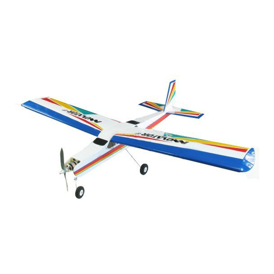
ALMOST READY TO FLY
Specifications
Wing Span --------------------------55.0 in ------------------------139.6cm.
Wing Area --------------------------486.7 sq.in ------------------ 31.4 dm.
Weight ----------------------------- 2.9 - 3.1lbs ------------ 1300 - 1600g.
Length ------------------------------ 42.5 in-------------------------- 107.9cm.
Need to Complete
Speed Control: 45 - 50 amp.
Recommended Battery 3-cell 2200mAh to 3200mAh Li-Po.
Radio : 4 channel with 5 digital servos ( medium size )
Kit features.
•
Ready-made—minimal assembly & finishing required.
•
Ready-covered covering.
•
Photo-illustrated step-by-step Assembly Manual.
Made in Vietnam.
ASSEMBLY MANUAL
MS:X10
2
Advertisement
Table of Contents

Related Manuals for Seagull EP Innovator EP

Summary of Contents for Seagull EP Innovator EP
- Page 1 ASSEMBLY MANUAL ALMOST READY TO FLY MS:X10 Specifications Wing Span --------------------------55.0 in ------------------------139.6cm. Wing Area --------------------------486.7 sq.in ------------------ 31.4 dm. Weight ----------------------------- 2.9 - 3.1lbs ------------ 1300 - 1600g. Length ------------------------------ 42.5 in-------------------------- 107.9cm. Need to Complete Speed Control: 45 - 50 amp. Recommended Battery 3-cell 2200mAh to 3200mAh Li-Po.
- Page 2 INNOVATOR- Instruction Manual. INTRODUCTION. Thank you for choosing the ARTF by SEAGULL EP. The was designed INNOVATOR INNOVATOR with the intermediate/advanced sport flyer in mind. It is a semi scale airplane which is easy to fly and quick to assemble. The airframe is conventionally built using balsa, plywood to make it stronger than the average ARTF , yet the design allows the aeroplane to be kept light.
-
Page 3: Hinging The Ailerons
www.seagullmodels.com Note: TOOLS & SUPPLIES NEEDED. The control surfaces, including the ailerons, elevators, and rudder, are Thick cyanoacrylate glue. prehinged with hinges installed, but the 30 minute epoxy. hinges are not glued in place. It is 5 minute epoxy. imperative that you properly adhere the Hand or electric drill. -
Page 4: Hinging The Elevator
INNOVATOR- Instruction Manual. ! 5) Turn the wing panel over and deflect the aileron in the opposite direction from the opposite side. Apply thin C/A glue to each hinge, making sure that the C/A penetrates into both the aileron and wing panel. ! 6) Using C/A remover/debonder and a paper towel, remove any excess C/A glue that may have accumulated on the wing or in the... -
Page 5: Propeller Installation
www.seagullmodels.com MOTOR Installtion. PROPELLER INSTALLATION. 2) Mounting the nose gear as shown in the following pictures. The propeller should not touch any part of the fuselage side. 3) Adjust the nose gear steering arm until the arm is parallel with the firewall. 4) Install the pushrod wire as shown. -
Page 6: Installing The Main Landing Gear
INNOVATOR- Instruction Manual. INSTALLING THE MAIN WHEELS. INSTALLING THE BATTERY- NOSE GEAR SERVO . Assemble and mounting the wheel as same as the way of nose wheel. See pictures below: See pictures below. Tie wrap. Battery. Nose gear servo. Battery. INSTALLING THE MAIN LANDING GEAR. - Page 7 www.seagullmodels.com ! 2) Insert the main gear wire into the mounting slot .Using the hardware provided, mount the main landing gear to the fuselage. Remove the covering. ! 3) The landing gear wire is held in place using two nylon landing gear straps and four 3mm x 10mm wood screws.
- Page 8 Fuselage bottom. Wing bottom. Remove the covering. Tail mounting. Remove the covering. Repeat the procedure for orther wing haft. TAIL SERVOS-LINKAGES. Repeat the procedure as same as the wing . Electric servo wire. Control horn. Pushrod. Fuselage bottom. Vertical fin. M3x15mm machine scvew.
-
Page 9: Installing The Receiver
Receiver. ATTACHMENT WING-FUSELAGE. Attach the aluminium tube into fuselage. Remove the covering. Electric wires. Switch. Fuselage bottom Plastic bolt. Wing brace. Battery. Plastic bolt. Insert two wing panels as pictures below: INSTALLING THE RECEIVER. -
Page 10: Control Throws
INNOVATOR- Instruction Manual. If the nose of the plane falls, the plane is nose heavy. To correct this first move the Wing bolt. battery pack further back in the fuselage. If this is not possible or does not correct it, stick small amounts of lead weight on the fuselage sides under the horizontal stabilizer. -
Page 11: Flight Preparation
www.seagullmodels.com !6) Check to ensure the control surfaces FLIGHT PREPARATION. are moving the proper amount for both low and high rate settings. ! A) Check the operation and direction of the elevator, rudder, ailerons and throttle. !7) Check the receiver antenna. It should ! B) Plug in your radio system per the be fully extended and not coiled up inside the manufacturer's instructions and turn every-...
Need help?
Do you have a question about the Innovator EP and is the answer not in the manual?
Questions and answers