
Summary of Contents for Rowe 198
-
Page 1: Table Of Contents
OPERATION MANUAL Table of contents Page Safety remarks Technical data Installation Instruction Assembly Floorstand Assembly roll-off device (option) Assembly stopper (option) Assembly table height adjuster Set-up Set-up Connection of machine Switch-on Materials cutable Cutting Cutting Guiding plate Trouble Shooting Alignment of cutting blade Wiring diagramme Technical modifications reserved 1/16... -
Page 2: Safety Remarks
1.0 Safety regulations - Read operation manual with safety notes before assembly and commissioning - Make sure that each operator is aware about this manual - Always keep this manual near the machine - Never ever short cut and mechanical or electrical separation switches - Make sure that the supply voltage is in accordance with the voltage indicated on the rating plate of the machine - Do not remove any fixed srewed parts... - Page 3 1.3. Dangerousness of this product This machine has been designed and built, according to the latest standards of technology as well as the approved rules of technology. Nonetheless, there might occur danger for the health of the operator or real values when using this product. This machine is only supposed to be used for those functions described in this operation manual.
- Page 4 Sufficient illumination needs to be ensured at the working place. CAUTION: Before starting maintenance or fixing works as well as when putting this machine out of operation for a longer period of time, the mains plug must be pulled out so to ensure that the machine will not be put back into operation unauthorizedly. 1.9.
-
Page 5: Technical Data
2.0 Technical data Space required for installation: appr. 0,85 m² Weight: appr. 50 kg Supply voltage: 230 V, 1NAC, 50/60 Hz Nominal current: 0,6 A Supply voltage: 115V, 1NAC, 50/60 Hz* Nominal current: 1,2 A * Connection value: 140 VA Sound pressure level appr. -
Page 6: Installation Instruction
3.0 Installation Instruction Unpack cutter and all parts of stand. Important: Please, strictly comply with the instructions described in continuation when mounting the stand. 3.1 Assembly Floorstand 4x M8x16 back front 4x M8x16 6/16 20_07_2017... - Page 7 4x M6x10 7/16 20_07_2017...
-
Page 8: Assembly Roll-Off Device (Option)
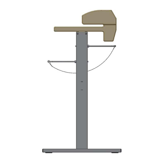
3.2. Assembly roll-off device (option) holding traverse (2x) paper rod stopper (2x) knurled screw M6x35 (4x) oval head screw M4x8 (2x) serrated lock washer J 4,3 (2x) 8/16 20_07_2017... -
Page 9: Assembly Stopper (Option)
3.3. Assembly stopper (option) List of components: stopper oval head screw M6x12 (2x) Put the stopper (position 1) onto the table profile. Push the hexagon nutes inside the table profile into position. The stopper is formed at its rear side in a way that they may locked angularly into the position desired in the sinked nute of the table profile. -
Page 10: Assembly Table Height Adjuster
3.4. Assembly table height adjuster (option) List of components: 1) adjusting plate (2x) 2) thread rail (4x) 3) screen surround left and right 4) flat head screw M6x12 5) screw M6x10 (4x) -- (part of delivery of serial machine) Pos. 2 Pos. -
Page 11: Set-Up
4.0 Set-up 4.1 Set-up The machine must stand horizontally and on solid ground. Do not put cutter with its back side to the wall. Keep a distance so that the plexi glass cover may be opened sufficiently. 4.2 Connection of machine Check beforehand whether the supply power corresponds with the voltage indicated on the rating plate. -
Page 12: Materials Cutable
4.4 Cuttable materials Do not process any crushed, curved, demolished or humid masters. Note: To avoid malfunctions, the following instructions should be strictly complied with: - during the cutting process, the master must not be moved - hold master at its outer edges The following materials may be cut electrically: Paper types plain paper 55 - 250 g/m²... -
Page 13: Cutting
5.0 Cutting 5.1 Cutting process - The cutting process will be performed electrically. - Push master to cutting edge - Fix requested cutting edge - Hold master with both hands on top of the table and push padle or rupturing ridge - The cutting head will cut the paper stripes Vorlage Pos. -
Page 14: Guiding Plate
5.2. Guiding plate A. Cutting of single masters For cutting of single copies, position guiding plate perpendicularly by means of the operating lever (right hand side of machine). Paper strips cut will be falling downwards into the collection bag. B. Cutting of paper web For cutting of paper webs, position guiding plate horizontally by means of the operation lever (right hand side of machine). -
Page 15: Trouble Shooting
6.0 Trouble Shooting 6.1 Alignment of cutting blade If the cutting blade (circular blade) has run onto the lower cutting blade, it may be aligned again with the help of the mounting tools. Open upper cover and push the cutting head towards the middle of the machine. Move cutting head zo the middle of machine and move revolving blade backwards by pressing button on axle of revolving blade. -
Page 16: Wiring Diagramme
Wiring Diagramme 16/16 20_07_2017...
Need help?
Do you have a question about the 198 and is the answer not in the manual?
Questions and answers