Table of Contents
Advertisement
Advertisement
Table of Contents

Summary of Contents for Orion Control Systems OE217-00
- Page 1 www.orioncontrols.com Digital Room Sensor Technical Guide...
-
Page 2: Table Of Contents
Outside Air Temperature Humidity Status Screen....................6 Unit Information Screen ............................6 Setpoint Adjust Screen ............................6 TROUBLESHOOTING ........................7 Temperature Sensor Testing for OE217-00 ......................7 APPENDIX ............................8 Sensor Confi guration and Test Screens ........................8 Sensor Confi guration & Test Screen ........................8 Pixel Test Screen .............................. -
Page 3: Overview
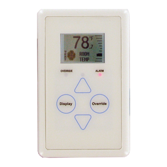
OVERVIEW Features Overview • Equipped with Push Buttons for changing the Zone Setpoint Temperature The OE217 series of Digital Room Sensors are used to sense Space Tem- • Equipped with an Override Button for forcing the VCM-X / perature only or Space Temperature & Space Humidity. See Figure 1. RNE / SA Controller into Occupied Operation from They can be used with the VCM-X E-BUS Controller (OE332-23E- Unoccupied Operation... -
Page 4: Basic Operation
Buttons and LEDs Sensor Operation LED Operation When power is fi rst applied to the OE217-00 Digital Room Sensor, the Refer to Figure 2 below for LED locations. sensor will display the Current Room Temperature or the Cooling/Heat- Alarm LED: The Alarm LED will blink when there is an alarm from ing Setpoint and the current setting of the slide off... -
Page 5: Mounting And Wiring
See Figure 3 for Digital Room Sensor dimensions. Important Wiring Considerations Optional Mounting Plate The OE217-00 and OE217-01 Space Sensors connect to the VCM-X Included with the Digital Room Sensor is a mounting plate that Controller, RNE, or SA-E-BUS using various lengths of TSDRSC can be used, if necessary, to cover the sensor sheet rock opening. -
Page 6: Sensor Operation
SENSOR SCREENS LCD Display Screens Setpoint Adjust Screen Main Sensor Display Screens Touching <> or <> will dis- There are 3 Main Sensor Display Screens. The fi rst screen displays play the Setpoint Adjust Screen. the Current Room Temperature or Cooling/Heating Setpoint, Opera- You can adjust the cooling tion Mode, Slide Off... -
Page 7: Troubleshooting
TROUBLESHOOTING Temperature/Resistance Chart Temperature – Resistance – Voltage for Temperature – Resistance – Voltage for Type III 10K Ohm Thermistor Sensors Type III 10K Ohm Thermistor Sensors Temp Resistance Temp Resistance (ºF) (Ohms) (ºF) (Ohms) 11379 93333 11136 80531 10878 69822 10625 60552... -
Page 8: Appendix
APPENDIX Sensor Confi guration and Test Screens Sensor Confi guration and Test Pixel Test Screen Screens To select the first option— Pixels—touch <> while at To access the Sensor Confi guration & Test Screens, you fi rst need to the Sensor Configuration & <Display>... -
Page 9: Lcd Backlight Test Screens
APPENDIX Sensor Confi guration and Test Screens Display Options - Temperature/Setpoint LCD Backlight Test Screens To select the third option— To access the Display Options <Override> DSPLY OPTIONS BACKLT—touch Screen, while at the Thermistor while at the Sensor Confi guration Averaging Screen, (Figure 15), UP = SETPOINT &... -
Page 10: Connecting To The Hvac Unit Controller
PRESSURE #LB102073-01-A #LB102033-01 EXPANSION SENSOR PRESSURE EXPANSION SENSOR Rev.: 1A OVERRIDE ALARM Display Override OE217-00 Or OE217-01 TSDRSC Cable Digital Room Sensor Figure 17: Digital Room Sensor to HVAC Unit Controller Wiring (VCM-X E-BUS Shown) Digital Room Sensor Technical Guide... -
Page 11: Connecting A Remote Sensor
If using the OE217-00 Temperature Only version of the sensor, you must If using the OE210 type Space Sensor as the remote sensor, you must fi rst remove the Digital Sensor’s back cover. You will see a loop of wire clip off... - Page 12 APPENDIX Connecting a Remote Sensor Remove C1 Capacitor OE217-00 & OE217-01 Digital Room Sensor Back View OE210 Space Sensor Shown With Temperature Sensor Back Cover Removed Back View Figure 19: Attaching the OE210 Space Room Sensor Digital Room Sensor Technical Guide...
- Page 13 The Circuit Board So They Can’t Touch Each Other. Sensor Shown With Back Cover Removed Figure 20: Wire Clipping Instructions For OE217-00 - Digital Room Temperature Only Sensor WARNING: DO NOT CLIP OFF OR REMOVE THE TEMPERATURE & HUMIDITY SENSING ELEMENT Sensing Element OE217-01 Digital Room Temperature &...
-
Page 14: Mounting Plate Dimensions
APPENDIX Mounting Plate Dimensions Optional Mounting Plate Included with the Digital Room Sensor is a mounting plate that can be used, if necessary, to cover the sensor sheet rock opening. This mounting plate screws onto the back of the housing base. The mounting plate is then mounted and covers the recessed space in the wall. - Page 15 NOTES Digital Room Sensor Technical Guide...
- Page 16 Form: OR-DRS-TGD-01M Printed in the USA August 2018 All rights reserved. Copyright 2018 AAON Controls • 8500 NW River Park Drive • Parkville, MO • 64152 Phone: 866-918-1100 www.orioncontrols.com Fax (816) 505-1101...
Need help?
Do you have a question about the OE217-00 and is the answer not in the manual?
Questions and answers