Table of Contents
Advertisement
Advertisement
Table of Contents

Summary of Contents for ATIMA AY3000i
- Page 1 AY3000i...
- Page 2 The engine exhaust from this product contains chemicals known to the State of California to cause cancer, birth defects or other reproductive harm. Exhaust contains poisonous carbon monoxide gas that can build up to dangerous levels in closed areas.Breathing carbon monoxide can cause unconsciousness or death.
- Page 3 • PLEASE READ AND UNDERSTAND THIS MANUAL COMPLETELY BEFORE OPERATING THE MACHINE. • ATIMA continually seeks advancements in product design and quality. Therefore, while this manual contains the most current product information available at the time of printing, there may be minor discrepancies between your engine and this manual. If there is any question concerning this manual, please consult ATIMA seller.
-
Page 4: Location Of Important Labels
1.LOCATION OF IMPORTANT LABELS Please read the following labels carefully before operating this generator. • Maintain or replace safety and instruction labels, as necessary. (FOR USA) AY3000i AC Output Salida de CA Rated Voltage 120V Rated Voltage 120V Current 21.7A... -
Page 5: Safety Information
2.SAFETY INFORMATION This generator is not designed for on-board use. Do not use it while installed on the vehicle. Do not modify the generator or use it with its parts removed. Do not allow children to operate the generator. Do not place any obstacles on the generator. EXHAUST FUMES ARE POISONOUS Never operate the engine in a closed area or it may cause unconsciousness and death within a... -
Page 6: Fue L Is Highly Flammable And Poisonous
FUE L IS HIGHLY FLAMMABLE AND POISONOUS Always turn off the engine when refuelling. Never refuel while smoking or in the vicinity of an open flame. Take care not to spill any fuel on the engine or muffler when refuelling. Do not leave the generator inside the vehicle or in the trunk. -
Page 7: Electric Shock Prevention
Keep the generator at least 1 m (3 ft) from buildings or other equipment, or the engine may overheat. a = 1 m (3 ft) Do not operate the engine with a dust cover or other objects covering it. When covering the generator, be sure to do so only after the engine and muffler have completely cooled down. -
Page 8: Connection Notes
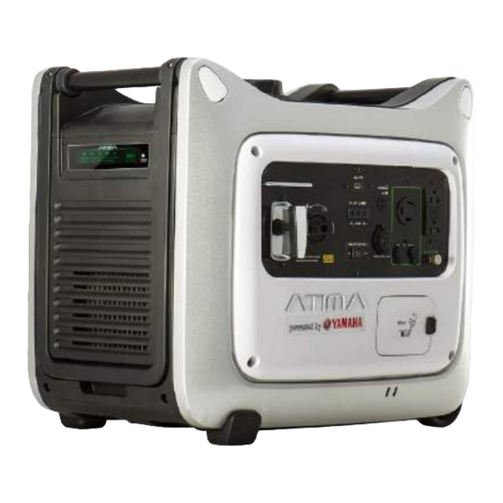
CONNECTION NOTES Avoid connecting the generator to commercial power outlet. Do not try parallel with generators of any other brand. 1.Correct 2.Incorrect CONNECTION WARNING Before the generator can be connected to a build- ing’s electrical system, a licensed electrician must install an isolation (transfer) switch in the build- ing’s main fuse box. - Page 9 3.DESCRIPTION 1.Carrying handles 2.Fuel level gauge 3.Fuel tank cap 4.Muffler 5.Wheels 6.Oil filler cap 7.Engine switch 8.Recoil starter 9.Control panel 10.Display 11.Folding handle 12.Fuel drain pipe...
-
Page 10: Control Panel
CONTROL PANEL FOR AY2500i FOR AY3000i 1.Low oil alarm indicator light 2.Overload indicator light 3.USB 4.Output indicator light 5.DC Circuit breaker 6.AC receptacle 1 7.AC receptacle 2 8.Smart Throttle 9.Cigar lighter 10.Parallel output 11.Ground terminal 12.AC Circuit Protector... -
Page 11: Engine Switch
DISPLAY The toggle button on the LCD screen can display the consumed power, voltage, current and frequency of the electrical appliances, and the total running hours of the generator set as well as the engine speed. When the generator is in normal operation, the right parts of the LCD screen will not display. - Page 12 Parallel Output Parallel Output These output are used for connecting two AY3000i or other ATIMA’s inverter generators for parallel operation . ATIMA approved parallel operation cable kit (optional equipment) is requied for parallel operation. This kit can be purchased from the seller .
- Page 13 GFCI Protector AC RESET METHOD: ENGINE PAUSE RESET TEST GFCI MONTHLY BUTTON ① START ENGINE. ② PUSH TEST BUTTON. TEST ③ RESET BUTTON SHOULD POP OUT. BUTTON ④ IF NORMAL OPERATION IS CONFRIMED. PUSH RESET BUTTON IN. ⑤ IF GFCI FALLS THIS TEST.DO NOT USE TAKE TO SELLER.
-
Page 14: Overload Indicator
OVERLOAD INDICATOR The overload indicator light (Yellow) comes on when an overload of a connected electrical device is detected, the inverter control unit overheats, or the AC output voltage rises. The electronic breaker will then activate, stopping power generation in order to protect the generator and any connected electric devices . The AC pilot light (Green) will go off and the overload indicator light (Yellow) will stay on, but the engine will not stop running. -
Page 15: Folding Handle
FOLDING HANDLE The foldable handle is intended for ease of transportation and should be folded when the generator is stationary.Do not rest objects on the handle when in the transport position. To Extend The Handle Lift the handle upward with both hands. To Fold The Handle Lower the handle with both hands until it clicks into place. -
Page 16: Pre-Operation Check
4.PRE-OPERATION CHECK Pre-operation checks should be made each time the generator is used. WARNING • The engine and muffler will be very hot after the engine has been run. • Avoid touching the engine and muffler while they are still hot with any part of your body or clothing during inspection or repair. -
Page 17: Engine Oil
ENGINE OIL WARNING • Make sure the engine oil is at the upper level of the oil filler hole.Add oil as necessary. Recommended engine oil: YAMALUBE 4 (10W-40), SAE 10W-30 or 10W-40 SAE #30 SAE #20 SAE 10W Recommended engine oil grade: API Service SE type or higher Engine oil quantity: 0.6 L NOTICE... -
Page 18: Operation
5.OPERATION WARNING • Never operate the engine in a closed area or it may cause unconsciousness and death within a short time. Operate the engine in a well ventilated area. • Before starting the engine, do not connect any electric devices. •... - Page 19 NOTICE • Do not allow the starting grip to snap back against the generator.Return it gently to prevent damage to the starter. 4.If the engine switch was turned to the “ ” position to start the engine,turn it to the “ON” position as the engine warms up. 5.If you wish to use the Throttle system,turn the Throttle switch to the “ON”...
- Page 20 CONNECTION Alternating Current (AC) 1.Start the engine. 2.Plug in to the AC receptacle. 3.Make sure the AC pilot light (Green) is on. AC pilot light Overload pilot light 4.Turn on any electric devices. WARNING • Be sure any electric devices are turned off before plugging them in. NOTICE •...
-
Page 21: Ac Parallel Operation
(red) stays on, consult your generator SELLER. During parallel operation, the Eco-Throttle switch should be in the same position on both generators. Connect the parallel operation cable kit between the two AY3000i generators following the instructions supplied with the kit. PARALLEL OPERATION CABLE KIT... - Page 22 30 minutes. Do not try parallel with generators of any other brand. Use only a ATIMA approved parallel operation kit (optional equipment) when connecting two AY3000i generators for parallel operation.
-
Page 23: Battery Charging
To restart charging the battery, turn the DC protector on by pressing its button to “ON”. • If the DC protector turns off again, stop charging the battery immediately and consult a ATIMA SELLER. •Follow instructions in the owner’s manual for the battery to determine the end of battery charging. -
Page 24: Stopping The Engine
Operating range of DC power supply (exclusively for charging 12-V battery) This power source is designed to charge batteries up to 40Ah that are half-discharged. Do not charge batteries of a higher capacity than 40Ah. 12V battery The time required for recharging a battery varies depending on the discharge level of the battery. -
Page 25: Periodic Maintenance
MAINTENANCE CHART WARNING Stop the engine before starting maintenance work. Use only ATIMA specified genuine parts for replacement. Ask an authorized ATIMA seller for further information. Every Preop-... -
Page 26: Spark Plug Inspection
7.Install the side cover and tighten the screws. CARBURETOR ADJUSTMENT The carburetor is a vital part of the engine. adjnsting should be left to an ATIMA seller with the professional kn owledge, specialized date and equipment to do so properly. -
Page 27: Engine Oil Replacement
ENGINE OIL REPLACEMENT WARNING • Avoid draining the engine oil immediately after stopping the engine. The oil is hot and should be handled with care to avoid burns. Warm up the engine for several minutes. Then stop the engine. Place wood blocks 3.5 in (90 mm) or greater under the generator as shown. 3.5 in (90 mm) or greater WOOD BLOCKS... - Page 28 5.Check the oil drain, gasket, oil filler cap and O-ring. Replace them if damaged. 6. Install the oil drain bolt. Oil drain bolt torque: 17 Nm (1.7 m·kgf, 12 ft·lbf) 7. Install the rubber cap on the buttom. Be sure to install securely to prevent from falling off during operation. 8.Add engine oil to the upper level.
-
Page 29: Muffler Screen And Spark Arrester
MUFFLER SCREEN AND SPARK ARRESTER WARNING • The engine and muffler will be very hot after the engine has been run. Avoid touching the engine and muffler while they are still hot with any part of your body or clothing during inspection or repair. 1.Remove the screws and the cover. -
Page 30: Air Filter
AIR FILTER 1. Remove the screws. Then remove the Remmovable service panel. Securing Screws Remmovable Air Filter Service Panel 2. Remove the air cleaner cover screw. Then remove the air cleaner cover. Foam Element Air Cleaner Cover Screw Air Cleaner holder Air Cleaner Cover 3. -
Page 31: Fuel Tank Filter
NOTICE • Do not wring out the foam element. This couldcause it to tear. • Be sure the foam element sealing surface matches the air filter so there is no air leak. NOTICE • The engine should never run without the foam element; excessive piston and cylinder wear may result. -
Page 32: Troubleshooting
Pull the recoil starter and check the Consult an spark plug for spark strength. Add engine oil. (See “ WARNING ”) ATIMA seller WARNING Check the spark plug. To prevent FIRE HAZARDS be 9 Type: BPR4ES sure fuel is not present in the 9 Gap: 0.7–0.8 mm (0.028–0.031 in) -
Page 33: Drain The Fuel
STORAGE Long term storage of your generator will require some preventive procedures to guard against deterioration. DRAIN THE FUEL WARNING Fuel is highly flammable and poisonous. Check SAFETY INFORMATION ” “ carefully. NOTICE Immediately wipe off spilled fuel with a clean, dry, soft cloth, since fuel may deteriorate painted sur faces or plastic parts. - Page 34 4.Tighten the drain screw after clean the fuel. 5.Remove the spark plug, pour about one tablespoon of SAE 10W-30 or 20W-40 motor oil into the spark plug hole and install the spark plug. Recoil start the engine by turning over several times (with ignition off) to coat the cylinder walls with oil. 6.Pull the recoil starter until you feel compression.
- Page 35 TRANSPORTING Do not lay the generator on its side when moving, storing, or operating it. Oil may leak and damage the engine or your property. If the generator has been used, allow it cool for at least 15 minutes before loading the generator on the transport vehicle. A hot engine and exhaust system can burn you and can ignite some material.
-
Page 36: Specifications
7.SPECIFICATIONS Model AY2500i Rated frequency (Hz) Rated voltage (V) Rated current (A) 17.5 Rated rotation speed [r/min] 3300 Rated output (KVA) Max. output (KVA) DC output DC voltage 12V-8A Electric circuit breaker Available Phase number Single phase Engine Model Typ YAMAHA MZ175 Type Single cylinder,air-cooled,4 stroke,gasoline engine... - Page 37 Model AY3000i Rated frequency (Hz) Rated voltage (V) Rated current (A) 21.7 11.3 10.8 Rated rotation speed [r/min] 3600 Rated output (KVA) Max. output (KVA) DC output DC voltage 12V-8A Electric circuit breaker Available Phase number Single phase Engine Model Typ...
-
Page 38: Electric Wiring Diagram
8.ELECTRIC WIRING DIAGRAM...
Need help?
Do you have a question about the AY3000i and is the answer not in the manual?
Questions and answers
Does not start no power at all
The ATIMA AY3000i may not start and have no power due to the following possible causes:
1. Load connected at startup – A load should not be connected when starting the generator. Always start it with nothing plugged in to allow it to idle and warm up.
2. Use of ethanol fuel – Ethanol fuel can cause engine problems. Only non-ethanol fuel should be used.
3. Improper startup procedure – The choke must be set correctly, and the generator may require multiple pulls to start.
4. Battery charging issues – If charging a battery, incorrect connections or using the wrong type of battery (like VRLA) can cause problems.
5. DC protector off – If charging a battery, ensure the DC protector is turned on before connecting.
6. Poor connections – Loose or reversed battery charger leads can prevent proper operation.
Following proper startup and maintenance procedures is key to preventing these issues.
This answer is automatically generated