Table of Contents

Summary of Contents for Splashme SM-AC-1.0
- Page 1 INSTALLATION AND OPERATING INSTRUCTIONS SPLASHME AUTOMATION CONTROLLER 1.0 (SM-AC-1.0) Designed and manufactured in Australia splashmepool.com.au © Nymet Innovations Pty Ltd 2019 Patent Pending PCXT/AU2018/050995 Approval SAA-192316-EA...
- Page 2 SplashMe Automation Controller 1.0 | Installation and Operating Instructions Warnings Auxiliary Inputs: Auxiliary inputs to be connected to a separate 16A circuit and circuit breaker Outputs: Total power consumption of AUX 1, 2 & 3 should not exceed 10A ...
- Page 3 However, Nymet Innovations assumes no responsibility for the use of this material. Nymet Innovations Pty Ltd reserves the right to make changes to the material at any time and without notice. Refer to the SplashMe web site (www.splashmepool.com.au) for the most updated version.
-
Page 4: Section 1: Safety Instructions
It is essential that the installer should be a person with sufficient experience in pool equipment installation and be approved to install the SplashMe Automation Controller, so that all the instructions in this manual can be followed exactly. -
Page 5: Introduction To The Splashme Automation Controller
Users will also be able to see actual electricity cost savings from date of installation when an electricity tariff is included. Download SplashMe App The SplashMe App is available on iOS and Android mobile platforms. Download the App to continue with installation and setup. Google Play Store https://play.google.com/store/apps/details?id=au.com.nymet.splashme... -
Page 6: Symbols
NOTE indicates something of importance that should be acknowledged during the installation process Warning WARNING indicates a hazard which, if not avoided, could result in damage to the SplashMe Automation Controller, it not functioning properly, and/or physical human © Nymet Innovations Pty Ltd 2019 | Revised November 2019... -
Page 7: Led Definitions
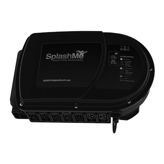
SplashMe Automation Controller 1.0 | Installation and Operating Instructions 1.4 LED definitions Once the SplashMe Automation Controller has been connected to a power source, the blue connection light will blink, and the device is ready for setup. Type Description Blue “slow” blinking Device is in “Direct Access”... -
Page 8: List Of Connected Equipment
SplashMe Automation Controller 1.0 | Installation and Operating Instructions 1.5 List of connected equipment Outlet ID# Connected Appliance Filter Pump AUX 1 AUX 2 AUX 3 AUX 4 AUX 5 AUX 6 AUX 7 AUX 8 pH Doser Notes: © Nymet Innovations Pty Ltd 2019 | Revised November 2019... -
Page 9: Table Of Contents
3.1 – Selecting suitable mounting location .............. 18 3.2 - Installing the multi-probe ................19 3.3 – Mounting to wall .................... 20 3.4 – Fixing the SplashMe Automation Controller to the wall bracket ...... 22 3.5 – Plumbing ....................... 23 3.6 – Pressure sensor connection ................26 3.7 –... - Page 10 SplashMe Automation Controller 1.0 | Installation and Operating Instructions 5.2.1 – Removing and refitting the front cover ........... 42 5.2.2 – Low voltage auxiliary connection ............42 5.2.3 – Roof temperature sensor (if solar is used) ..........44 5.2.4 – Auxiliary connections (actuator valves, equipment, 15A-3phase)... 44 5.2.5 - 12VDC peristaltic pump for acid dosing ..........
-
Page 11: Section 2 - System Overview
(up to 2 kW) into a variable speed pump. Using the pool size entered during setup and the information detected by the flow sensor, the SplashMe Automation Controller will efficiently run the filter pump whilst maintaining water cleanliness. -
Page 12: What's In The Box
SplashMe Automation Controller 1.0 | Installation and Operating Instructions 2.2 – What’s in the box Only use the equipment supplied by Nymet Innovations. Use of non-approved components may result in damage to SplashMe Automation Controller and void warranty Number Description... -
Page 13: Technical Specifications
SplashMe Automation Controller 1.0 | Installation and Operating Instructions 2.3 – Technical specifications Multi-Function Button © Nymet Innovations Pty Ltd 2019 | Revised November 2019... - Page 14 SplashMe Automation Controller 1.0 | Installation and Operating Instructions INPUTS Inputs 1-3: 240V~, 50Hz, 10A Max Input 4: 240V~50Hz, 10A Max WARNING: Auxiliary inputs to be connected to a sperate 16A circuit and circuit breaker OUTPUTS 2 kW water cooled variable frequency drive ...
- Page 15 SplashMe Automation Controller 1.0 | Installation and Operating Instructions pH sensor Operating temperature: 0-60degC pH Range: 0-14 pH Slope: >98% pH sensor: Glass Bullet Accuracy: +- 0.1 pH unit ORP sensor Operating Temperature: 0-60degC ...
-
Page 16: Electrical Specification
SplashMe Automation Controller 1.0 | Installation and Operating Instructions 2.4 – Electrical specification Primary input 240V~, 50Hz, 9.2A, 2000W Auxiliary inputs Input 1-3: 240V~, 50Hz, 10A Max Input 4: 240V~, 50Hz, 10A Max Outputs VSD : 240V~, 9.0A Max AUX 1-3:... -
Page 17: Preparation For Installation
The SplashMe Automation Controller has an inbuilt ORP sensor. It works by measuring the dissolved oxygen in the water. More contaminants in the water result in less dissolved oxygen because the organics are consuming the oxygen and therefore a lower ORP level. - Page 18 SplashMe Automation Controller 1.0 | Installation and Operating Instructions Before proceeding, ensure following items are available to successfully install and connect the SplashMe Automation Controller. Item Description Desirable Essential Android/iOS Smart Data charges may apply phone Wi-Fi Internet...
-
Page 19: Section 3 - Installation
The SplashMe Automation Controller must be mounted within 1.5 m from the power supply. Wi-Fi requirements: The SplashMe Automation Controller must be in range of the home Wi-Fi network if the deivce is to be controlled remotely. The home network may need to be extended to reach to selected mounting location. -
Page 20: Installing The Multi-Probe
SplashMe Automation Controller 1.0 | Installation and Operating Instructions 3.2 - Installing the multi-probe The multi-probe comes installed in a protective cap which contains a storage solution. This storage solution keeps the pH probe glass hydrated and ensures the probe will be ready to use as soon as soon as it is installed. -
Page 21: Mounting To Wall
SplashMe Automation Controller 1.0 | Installation and Operating Instructions 3.3 – Mounting to wall Hollow wall / timber installation Instructions Position the Mounting bracket in the desired location on the wall with the hanging hooks pointing up. Ensure wall bracket is level and mark the 4 outer holes (Fig 2: A, B, C and D) with... - Page 22 SplashMe Automation Controller 1.0 | Installation and Operating Instructions Masonry wall installation Position the Mounting bracket in the desired location on the wall with the hanging hooks pointing up Ensure wall bracket is level and mark the 4 outer holes with a pencil –...
-
Page 23: Fixing The Splashme Automation Controller To The Wall Bracket
3.4 – Fixing the SplashMe Automation Controller to the wall bracket Instructions Remove SplashMe Automation Controller from the box and line up the 3 slots in the rear bracket with the 3 hooks on the wall bracket. Allow the SplashMe Automation Controller to hang on the 3 hooks so the bottom two screw holes align. -
Page 24: Plumbing
The SplashMe Automation Controller comes complete with a flow sensor to monitor exactly how long a filter pump needs to run to maintain a clean pool. For the flow sensor to operate, it is essential that the SplashMe Automation Controller be plumbed in line with the pool filtration equipment. - Page 25 SplashMe Automation Controller 1.0 | Installation and Operating Instructions Now the SplashMe Automation Controller will be ready to plumb into the filter pump water circuit. Locate the pipe that runs from the Return (outlet) of the sand filter/cartridge filter to the next piece of equipment (usually a heater or chlorination cell).
- Page 26 SplashMe Automation Controller 1.0 | Installation and Operating Instructions © Nymet Innovations Pty Ltd 2019 | Revised November 2019...
-
Page 27: Pressure Sensor Connection
The SplashMe Automation Controller has an built-in pressure sensor for real-time monitoring of the main pool filter condition. Working with either a sand filter or cartridge filter, once connected the SplashMe App will alert users when the filter needs to be cleaned or a backwash needs to be performed. -
Page 28: Ph Acid Dosing / Peristaltic Pump Installation
3.7 – pH acid dosing / peristaltic pump installation The SplashMe Automation Controller comes with a 12VDC pH Acid dosing peristaltic pump. Before connecting the pump to the SplashMe Automation Controller, the pump will need to be installed as per below instructions. - Page 29 SplashMe Automation Controller 1.0 | Installation and Operating Instructions Injection point installation The injection point is the last connection before the pipe work returns back to the pool meaning it must be installed inline, after the SplashMe Automation Controller, heaters and solar booster pumps. Instructions...
- Page 30 SplashMe Automation Controller 1.0 | Installation and Operating Instructions Filter Basket, Check Valve and Feed tube installation Next, connect the acid drum to the dose pump. A concentration of 110g/L hydrochloric acid is required for the dosing system. Most hydrochloric acid is sold at a concentration of 330g/L. To achieve correct concentration, dilute 1 litre of hydrochloric acid with 2 litres of tap water.
- Page 31 SplashMe Automation Controller 1.0 | Installation and Operating Instructions © Nymet Innovations Pty Ltd 2019 | Revised November 2019...
-
Page 32: Section 4 - Main Electrical Supply
3 x 10A RCD protected socket outlets each connected to a separate 16A circuit and circuit breaker. The socket outlets need to be mounted within 1.5 m of the SplashMe Automation Controller to ensure the supplied plugs will reach. -
Page 33: Equipotential Bonding Connection
The Australian and New Zealand Standards requires pool equipment to be bonded to each other. Check local codes NEC and/or local installation codes for installation requirements. A 6mm bonding terminal is provided on the back of the SplashMe Automation Controller. This terminal is connected to the earthed water circuit and Note ... -
Page 34: Section 5 - Connecting Equipment
Primary input The Primary Input lead at the rear of the device supplies power to the SplashMe Automation Controller. This plug also supplies power to the single speed filter pump (up to 2 kW). - Page 35 SplashMe Automation Controller 1.0 | Installation and Operating Instructions 5.1.2 - Filter pump VSD (Variable Speed Drive) Output The SplashMe Automation Controller is equipped with a water cooled 2000W single phase variable speed drive. By connecting a new or existing single speed filter pump into the filter...
-
Page 36: Sanitisation Equipment
Saltwater / Mineral chlorinator The SplashMe Automation Controller will automatically maintain a pre-set ORP level entered in the App settings. Whenever the filter pump is functioning, the SplashMe Automation Controller measures the ORP and controls the saltwater chlorinator to achieve the set levels. - Page 37 SplashMe Automation Controller 1.0 | Installation and Operating Instructions Liquid chlorine doser The SplashMe Automation Controller can also control a peristaltic dose pump to accurately dose liquid chlorine to a pool. This is an alternative method to the salt chlorinator system.
-
Page 38: Solar Heating
The SplashMe Automation Controller will then control the solar heating to achieve and maintain the pre-set level. If no filter pump schedule is running, the SplashMe Automation Controller will periodically measure the water temperature by activating the filter pump for several minutes. - Page 39 SplashMe Automation Controller 1.0 | Installation and Operating Instructions Instructions Check the power requirements of the solar pump and connect to the most suitable output using the supplied adaptor. © Nymet Innovations Pty Ltd 2019 | Revised November 2019...
- Page 40 SplashMe Automation Controller 1.0 | Installation and Operating Instructions Filter pump – Booster pump This type of configuration is used when an independent pump cannot be installed. The solar system recirculation is distributed by the existing filter pump. In this case a booster pump is used to pull water from the filter pump suction line and divert it to the roof.
- Page 41 SplashMe Automation Controller 1.0 | Installation and Operating Instructions Instructions Read section 5.2.3 to connect any actuator valves If connecting a booster pump, check the power requirements and connect to the most suitable output using the supplied adaptor. Note ...
-
Page 42: Connecting Additional 240V Equipment
SplashMe Automation Controller 1.0 | Installation and Operating Instructions 5.1.5 – Connecting additional 240v equipment Any of the auxiliary outlets (AUX 1, 2, 3 or 4) can be used to control equipment additional to those mentioned above. Examples of additional 240v auxiliary equipment includes but is not limited to water features, spa blowers, pool and garden lighting and pool cleaners. -
Page 43: Connecting Low Voltage Equipment (Hard Wired)
SplashMe Automation Controller 1.0 | Installation and Operating Instructions 5.2 - Connecting low voltage equipment (hard wired) 5.2.1 – Removing and refitting the front cover Instructions Removal Remove the 8 screws (see diagram) and remove the front cover. Refitting Ensure that the O-Ring is in position and clear of any debris Place the front cover in position and ensure the Multi-Function button has come through the cover and can be pressed. - Page 44 SplashMe Automation Controller 1.0 | Installation and Operating Instructions 5.2.2 – Low voltage auxiliary connection The SplashMe Automation Controller comes with low voltage outputs which can be used to control equipment. See Diagram Any of the auxiliary outlets (AUX 5, 6, 7 & 8) can be used to control equipment additional to those mentioned above.
-
Page 45: Roof Temperature Sensor (If Solar Is Used)
SplashMe Automation Controller 1.0 | Installation and Operating Instructions 5.2.3 – Roof temperature sensor (if solar is used) The SplashMe Automation Controller comes with its own ambient roof temperature sensor. It is generally used by the solar controller to control the solar pump. Even if the solar controller function is not used, it still may be beneficial to install as it will provide a real time reading of the ambient temperature on the app. -
Page 46: Auxiliary Connections (Actuator Valves, Equipment, 15A-3Phase)
5.2.4 – Auxiliary connections (actuator valves, equipment, 15A-3phase) Actuator valves The SplashMe Automation Controller has 4 x volt-free terminal blocks suitable to control actuator valves. These outputs are AUX5, AUX6, AUX7, AUX8. Note the connection outlet number so it can be correctly assigned when setting up the SplashMe App. - Page 47 SplashMe Automation Controller 1.0 | Installation and Operating Instructions Warning All electrical connections and installations to be done by a licenced electrician AUX 5-8 is for the connection of Safety Isolated (SELV) Supply / Loads only © Nymet Innovations Pty Ltd 2019 | Revised November 2019...
- Page 48 1-24V AC/DC that are Safety Isolated (SELV) Supply / Loads only. When using the SplashMe Automation Controller to control larger equipment such as 15A pumps or 3 phase equipment, a licenced electrician will be required to configure a relay/contactor setup to connect to the auxiliary outputs.
-
Page 49: 12Vdc Peristaltic Pump For Acid Dosing
SplashMe Automation Controller 1.0 | Installation and Operating Instructions 5.2.5 - 12VDC peristaltic pump for acid dosing The SplashMe Automation Controller comes fully equipped with a 12V Peristaltic Acid Pump. In a typical swimming pool environment, the tendency is for the pH to increase. Dosing the water with hydrochloric acid is the main method used to lower the pH back into balance. -
Page 50: Gas Heater Or Electric Heat Pump
App settings. Whenever the filter pump is functioning, the SplashMe Automation Controller measures the water temperature using the in-built temperature sensor. The SplashMe Automation Controller will control the pump to heat the water to achieve and maintain the pre-set pH level. -
Page 51: Powering Up
After installing the physical hardware and equipment the SplashMe Automation Controller will be ready to power up. At this point the SplashMe Automation Controller should be mounted to wall (see 3.4) and plumbed in (see 3.5). All equipment should also be connected and ready to power Run the main filter pump manually and check the system for any leaks. -
Page 52: Section 6 - Local Control
When the device beacons out a unique “SplashMe_{example1234}” SSID and can be connected to like any normal Wi-Fi network. To use the device in this mode, users (with mobile device) must be within direct Wi-Fi range of the SplashMe Automation Controller at all times. - Page 53 SplashMe Automation Controller 1.0 | Installation and Operating Instructions 6.2 – Motor error hard reset In the event of a system error the front of the SplashMe Automation Controller will have the RED light illuminated. Refer to the app for info on the error.
-
Page 54: Section 7 - Splashme App
SplashMe Automation Controller 1.0 | Installation and Operating Instructions Section 7 – SplashMe App Once the SplashMe Automation Controller has been installed, the installer will need to download the SplashMe App from either Apple App or Google Play stores. Google Play Store https://play.google.com/store/apps/details?id=au.com.nymet.splashme... -
Page 55: Section 8 - Maintenance
SplashMe Automation Controller 1.0 | Installation and Operating Instructions Section 8 – Maintenance While the SplashMe Automation Controller will be a key piece of equipment for easy, stress- free maintenance, it is recommended owners follow a regular maintenance schedule to keep the pool clean and healthy. -
Page 56: Cleaning Multiprobe
Holding the probe by the cable, gently swirl the probe in a dilute hydrochloric acid solution for two minutes Rinse the probe in clean water and replace into the back of the SplashMe device and hand tighten the black locking nut... -
Page 57: Peristaltic Pump - Servicing Squeeze Tubes
SplashMe Automation Controller 1.0 | Installation and Operating Instructions 8.3 Peristaltic pump - servicing squeeze tubes Peristaltic pump squeeze tubing needs to be replaced every 12 months. If the pool has high chlorine demand or is in a semi commercial/commercial application, squeeze tubing may need to be replaced more frequently. - Page 58 SplashMe Automation Controller 1.0 | Installation and Operating Instructions Check replacement squeeze tube has the supplied barbed nipples attached to each end Insert replacement squeeze tube assembly (tubing with barbed nipples) from input (left side) to output right side. Insert input barbed nipple and align round edge of barbed nipple with locator...
- Page 59 SplashMe Automation Controller 1.0 | Installation and Operating Instructions Insert the output barbed nipple into the locator, round edge first Replace cover and 6 screws © Nymet Innovations Pty Ltd 2019 | Revised November 2019...
-
Page 60: Section 9 - Troubleshooting
SplashMe Automation Controller 1.0 | Installation and Operating Instructions Section 9 – Troubleshooting See SplashMe website (www.splashmepool.com.au/support) for further information © Nymet Innovations Pty Ltd 2019 | Revised November 2019... -
Page 61: Section 10 - Warranty
SplashMe Automation Controller 1.0 | Installation and Operating Instructions Section 10 – Warranty Refer to Warranty Policy on the SplashMe website (www.splashmepool.com.au) © Nymet Innovations Pty Ltd 2019 | Revised November 2019... -
Page 62: Section 11 - Product Support
For user product updates, information and support visit www.splashmepool.com.au or email info@splashmepool.com.au. The contents of this manual will be periodically updated or revised due to product updates. The latest version of the SplashMe Installation/User Guide will be available at www.splashmepool.com.au/support Company contact details Company Nymet Innovations Website www.splashmepool.com.au... - Page 63 SplashMe Automation Controller 1.0 | Installation and Operating Instructions NOTES: © Nymet Innovations Pty Ltd 2019 | Revised November 2019...
- Page 64 SplashMe Automation Controller 1.0 | Installation and Operating Instructions © Nymet Innovations Pty Ltd 2019 | Revised November 2019...
Need help?
Do you have a question about the SM-AC-1.0 and is the answer not in the manual?
Questions and answers