
Related Manuals for Eagle T20CF

Summary of Contents for Eagle T20CF
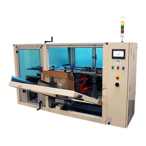
- Page 1 Operations Manual Eagle T20CF Carton Erector READ ALL INSTRUCTIONS CONTAINED IN THIS MANUAL PRIOR TO MACHINE INSTALLATION! - 1 -...
-
Page 2: Table Of Contents
Contents page Safety & Warnings Specifications Setup and Installation Transportation Tape Head Installation Power Supply Operation Standard Operation Case Erector Carton Size Adjustment Feeding Adhesive Tape Control Panel Operation LCD Display Operation Maintenance & Troubleshooting Maintenance Troubleshooting Illustrations & Parts List Replacement Parts Carton Storage Shelf Carton Storage Table... -
Page 3: Safety & Warnings
• Protective shielding and covers are properly installed • Machine is on stable ground and casters are in the locked position. The Eagle T20CF is designed to automatically shut down if the control panel is opened while the machine is in operation. -
Page 4: Specifications
2. Specifications Power Requirement 220VAC, 50/60Hz (Single Phase) Air Supply 85psi (6Kgf/cm Tape Width 2-3in (48-72mm) Working Speed 0-12 cases per minute Carton Length 11-20.5in Carton Width 7-11in Carton Height 11-24in Machine Length 80.7in Machine Width 86.6in Machine Height 53in Weight 882lbs Operational Environment... -
Page 5: Setup And Installation
3. Machine Setup and Installation TAKE CARE TO AVOID DAMAGE TO THE MOTOR AND ASSEMBLY WHILE LIFTING OR TRANSPORTING THE MACHINE! 3.1 Transportation Use a fork lift or tow motor to remove the machine from its shipping container or pallet. 3.2 Tape Head Installation Remove the front supporting shaft. -
Page 6: Operation
4. Operation 4.1 Standard Operation Prior to operating the machine, please confirm that 1. The proper voltage is being supplied to the motor 2. All fasteners and protective covers are securely in place 3. All electronic components are dry Machine Operation 1. -
Page 7: Carton Size Adjustment
4. Operation 4.3 Carton Size Adjustment Width/2 Adjustment Width Adjustment Press Plate Height Adjustment Length + Width Adjustment Length Adjustment Width Adjustment - 7 -... -
Page 8: Feeding Adhesive Tape
4. Operation 4.4 Feeding the Adhesive Tape Adhesive tape Adhesive tape core adjustment button Guide tape roller Unidirectional lozenge pattern roller Guide tape board Press tape board Guide tape roller Rubber roller Adhesive tape 4.5 Control Panel Operation Before operating the machine, the operator should review the features and functions of every switch to ensure the correct and safe operation of the machine. -
Page 9: Lcd Display Operation
4.6 LCD Display Operation Start Screen Once the machine has fully powered up, this screen will be displayed. Continue by pressing the button labeled “CONTINUE”. Automatic Mode There are two automatic operation modes. In the first mode, the machine will run continuously until carton stock has been exhausted. - Page 10 4.6 LCD Display Operation Step-by-Step This screen permits the user to run the machine one step at a time. The first step is to load the carton into the folding position. This is accomplished by pressing the green icon labeled “LOAD BOX INTO FOLDING POSITION”.
-
Page 11: Maintenance & Troubleshooting
5. Maintenance & Troubleshooting 5.1 Maintenance TURN POWER SWITCH TO THE OFF POSITION AND DISCONNECT FROM POWER SUPPLY PRIOR TO PERFORMING ANY MAINTENANCE OR REPAIRS TO THE MACHINE Regular maintenance will prolong machine life and lower the chance of malfunctions. 1. - Page 12 5. Maintenance & Troubleshooting 5.2 Troubleshooting (continued) Carton does not feed properly The base of the carton is not level Adjust carton alignment while erecting to the machine. Suction and placement of carton Air pressure is out of range Adjust supply air pressure to error match machine requirements Suction disk malfunction...
-
Page 13: Replacement Parts
6. Machine Parts & Illustrations 6.1 Replacement Parts Description Part Number Case-Sealing Blade Machine Core Extension Spring Chain Electromagnetic Valve Travel Switch (photoelectric, prox) Fuse Magnetic Inductive Switch Vacuum Suction Disk Motor 10 Belt - 13 -... -
Page 14: Carton Storage Shelf
6. Machine Parts & Illustrations 6.2 Carton Storage Shelf Description Part Number Carton Storage Table Carton Storage Table Lifting Body - 14 -... - Page 15 6. Machine Parts & Illustrations 6.3 Carton Storage Table Assembly - 15 -...
- Page 16 6. Machine Parts & Illustrations 6.3 Carton Storage Table Assembly (continued) Description Part Number Drag Hook Base CF-20TX-159 Drag Hook CF-20TX-60 Guide Carton Board Filler Strip CF-20TX-57 Guide Carton Board CF-20TX-56 Send Carton Guide Rod CF-20TX-58 Baring Base SBLF 202 Work Table Screw Rod I CF-20TX-62 Screw Nut...
- Page 17 6. Machine Parts & Illustrations 6.4 Carton Pre-Storage Table Lifting Body Assembly - 17 -...
-
Page 18: Carton Pre-Storage Table Lifting Body
6. Machine Parts & Illustrations 6.4 Carton Pre-Storage Table Lifting Body Assembly (continued) Description Part Number Chain Lifting Screw Rod Chain Wheel FJ-1A-130 Lifting Supporting Board CF-20TX-69 Bearing 6004 Linear Slide Base I CF-01-04-047.1 Lifting Screw Nut Base FJ-1A-150 Sliding Bush CF-20TX-178 Work Table Supporting Rod CF-20TX-84... -
Page 19: Back Cover Carton Push & Fold
6. Machine Parts & Illustrations 6.5 Back Cover Carton Fold & Push Device - 19 -... - Page 20 6. Machine Parts & Illustrations 6.5 Back Cover Carton Fold & Push Device (continued) Description Part Number Pearl Eye Joint SC40 Linear Bearing LM25UU Linear Sliding Base CF-20TX-38 Linear Filling Strip CF-20TX-21 Push Carton Cylinder Front Shaft CF-20TX-28 Push Carton Rod Combination CF-20TX-33 Molding Bent Rod CF-20TX-36...
-
Page 21: Machine Frame
6. Machine Parts & Illustrations 6.6 Machine Frame - 21 -... - Page 22 6. Machine Parts & Illustrations 6.6 Machine Frame Description Part Number Machine Frame CF-20TX-174 Foot Cup Side Sealing Plate CF-20TX-180 Electrical Box CF-20T-2-3 Chain Lid Plate CF-20TX-96 End Sealing Plate I CF-20TX-181 End Sealing Plate II CF-20TX-183 Top Beam CF-20TX-118 Stand Rod Combination CF-20TX-123 10 Stand Rod L Plate...
- Page 23 6. Machine Parts & Illustrations 6.7 Front Cover-Folding Assembly Description Part Number Machine Core Support Plate CF-20TX-15 Cylinder MAL32x30-CA Folding front Cylinder Back Shaft CF-20TX-4 Connecting Rod CF-01-04-190 Transition Plate Fixing Bar CF-20TX-13 Bearing 6004 Transition Plate CF-20TX-14 Folding Front Gear CF-20TX-3 Folding Front Plate Combination CF-20TX-7...
- Page 24 14 Brush Shelf CF-20T-201 15 Hair Brush 16 Press Plate FJ-2A-134 6. Machine Parts & Illustrations 6.8 Conveyer Belt Assembly - 24 -...
-
Page 25: Conveyer Belt
6. Machine Parts & Illustrations 6.8 Conveyer Belt Assembly (continued) Description Part Number Bearing Base SBLF 204 Chain Left & Right Screw Rod I FJ-1A-55 Handle Drive Chain Wheel CF-01-05-3.1 Left & Right Screw Rod II CF-20TX-12 Side Input Top Plate CF-20TX-11 Cover Plate Supporting Post CF-18T-159... - Page 26 6. Machine Parts & Illustrations 6.9 Vacuum-Assisted Carton Placer Assembly - 26 -...
-
Page 27: Vacuum-Assisted Carton Placer
6. Machine Parts & Illustrations 6.9 Vacuum-Assisted Carton Placer Assembly (continued) Description Part Number Large Pulley CF-20TX-127 Connecting Rod Assembly CF-20TX-132 Small Pulley CF-20TX-128 Pulley Shaft Cf-20TX-133 Linear Sliding Base I CF-01-04-047.1 Width Guide Rod CF-20TX-94 Guide Rod L Plate CF-20TX-93 Vacuum Disc Upright Sliding Rod CF-20TX-92... - Page 28 - 28 -...
- Page 29 6. Machine Parts & Illustrations 6.10 Blocking Pin & Press Plate Assembly - 29 -...
-
Page 30: Blocking Pin & Press Plate
6. Machine Parts & Illustrations 6.10 Blocking Pin & Press Plate Assembly (continued) Description Part Number Lifting Body FJ-1A-30 Upright Pose Roller Wheel FJ-1A-105 Screw Nut FJ-1A-106 Supporting Plate FJ-1A-69 Bearing 61905 Lifting Screw Rod FJ-1A-71 Handle Carton Rack Upper Block CF-20TX-100 Blocking Pin CF-20TX-98... - Page 31 6. Machine Parts & Illustrations 6.11 Left & Right Cover Folder Assembly - 31 -...
-
Page 32: Left & Right Cover Folder
6. Machine Parts & Illustrations 6.11 Left & Right Cover Folder Assembly (continued) Description Part Number Left / Right Folding Base CF-20TX-150 Bearing Base Padding Block CF-20TX-136 Conveyor Gear CF-20TX-135 Bearing Base UCPA 204 Clamping Block CF-20TX-134 Left / Right Folding Rod CF-20TX-144 Folding Rod Closure Head CF-20TX-141... - Page 33 6. Machine Parts & Illustrations 6.12 Carton Sealer - Front Roller Assembly - 33 -...
-
Page 34: Carton Sealer - Front Roller
6. Machine Parts & Illustrations 6.12 Carton Sealer - Front Roller Assembly (continued) Description Part Number Bracket FJ-01-09 Front & Back Roller Shaft FJ-00-10 One-Way Roller Shaft FJ-E-38-01 Front Rubber Roller Wheel FJ-E-41-01 Front Roller Wheel Press Spring FJ-H-02 Front Roller Wheel Washer FJ-04-06 Cross Flat Trench Screw M4x12... -
Page 35: Carton Sealer - Rear Roller
6. Machine Parts & Illustrations 6.13 Carton Sealer - Rear Roller Assembly Description Part Number Rear Connecting Plate FJ-01-13 Front & Back Roller Shaft FJ-00-10 Back Rubber Roller Wheel FJ-40-03 Main Shaft FJ-00-06 Main Shaft Sleeve FJ-02-05 Back Locating Ring FJ-02-06 Bearing 6800Z (26800) -
Page 36: Carton Sealer - Roller
6. Machine Parts & Illustrations 6.14 Carton Sealer - Roller Assembly Description Part Number Lock Nut Washer FJ-02-03 Bearing HF1216 Roller FJ02-00-03 Shaft FJ-00-04 Spacer FJ-02-01 - 36 -... -
Page 37: Guide Pulley
6. Machine Parts & Illustrations 6.15 Guide Pulley Assembly Description Part Number Guide Pulley Shaft Axle Sleeve Washer FJ-02-03 Flip Washer HF1216 Hex Socket Head Screw FJ02-00-03 - 37 -... -
Page 38: Tape Knife
6. Machine Parts & Illustrations 6.16 Tape Knife Assembly Description Part Number Knife Back Plate Shaft FJ-00-00 Torsion Spring FJ-H-01 Blade Carrier Cover FJ-01-06 Sponges Knife Board FJ-40-04 Blade Blade Carrier Block FJ-01-07 Hex Socket Screw M4x16 10 Cross Flat Touch Screw M4x12 - 38 -... -
Page 39: Tape Dispenser
6. Machine Parts & Illustrations 6.17 Tape Dispenser Assembly Description Part Number Tape Head Frame FJ-05-01 Tape Wheel Axle Sleeve FJ-02-12 Antiskid Washer FJ-50-01 Tape Wheel FJ-8-40-01 Packing Washer FJ-05-02 Pressure Spring FJ-H-08 Hand Nut FJ-00-14 Carrier Ring FJ-02-08 Washer 10 Lock Nut M5x40 - 39 -... -
Page 40: Tape Guide
6. Machine Parts & Illustrations 6.18 Tape Wheel Assembly Description Part Number Shaft FJ-00-09 Knurled Shaft Sleeve FJ-02-14 Tape Guide Wheel FJ-02-13 - 40 -... - Page 41 6. Machine Parts & Illustrations 6.19 Tape Press Assembly Description Part Number Shaft FJ-00-09 Tape Press Board FJ-01-05 Spring FJ-H-03 - 41 -...
- Page 42 6. Machine Parts & Illustrations 6.20 Tape Guide Assembly Description Part Number Spacer FJ-02-02 Shaft FJ-00-10 Shaft Sleeve FJ-02-10 Guide FJ-01-08 - 42 -...
-
Page 43: Electrical Diagrams
6. Machine Parts & Illustrations 6.21 Electrical Diagrams - 43 -... - Page 44 6. Machine Parts & Illustrations 6.20 Electrical Diagrams - 44 -...
- Page 45 6. Machine Parts & Illustrations 6.20 Electrical Diagrams - 45 -...
- Page 46 - 46 -...
- Page 47 6. Machine Parts & Illustrations 6.20 Electrical Diagrams - 47 -...
- Page 48 6. Machine Parts & Illustrations 6.20 Electrical Diagrams - 48 -...
- Page 49 6. Machine Parts & Illustrations 6.20 Electrical Diagrams - 49 -...
- Page 50 6. Machine Parts & Illustrations 6.20 Electrical Diagrams - 50 -...
Need help?
Do you have a question about the T20CF and is the answer not in the manual?
Questions and answers