Table of Contents
Advertisement
Advertisement
Table of Contents

Related Manuals for Field Tuff ATV-48ATVPS

Summary of Contents for Field Tuff ATV-48ATVPS
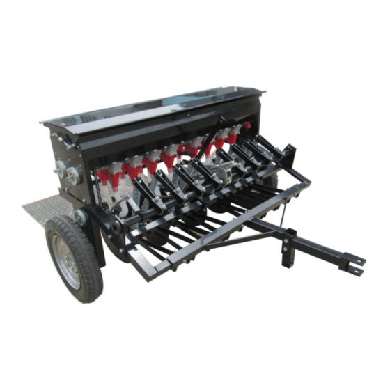
- Page 1 ATV Seeder OWNER’S MANUAL WARNING: Read carefully and understand all ASSEMBLY AND OPERATION INSTRUCTIONS before operating. Failure to follow the safety rules and other basic safety precautions may result in serious personal injury. Model # ATV-48ATVPS 20180601...
-
Page 2: Intended Use
Thank you very much for choosing this product! For future reference, please complete the owner’s record below: Model: Purchase Date: _______________ Save the receipt, warranty and these instructions. It is important that you read the entire manual to become familiar with this product before you begin using it. This product is designed for certain applications only. -
Page 3: Work Area
SAVE THESE INSTRUCTIONS WORK AREA • Keep work area clean, free of clutter and well lit. Cluttered and dark work areas can cause accidents. • Keep children and bystanders away while operating a seeder. Distractions can cause you to lose control, so visitors should remain at a safe distance from the work area. •... - Page 4 SAFETY PRECAUTIONS AND OPERATION RULES Note the following in order to avoid fertilizer burn: The seed rate should be controlled according to your field condition. Always inspect, maintain or adjust the seeder after each use. 3. While operating the seeder, keep area clean, free of clutter and well lit. Keep children and bystanders away.
- Page 5 ASSEMBLY Step #1: Remove the seeder from the crate. Step #2: Connect the Support seat (#2) to the Seeder Rack (#1), using four Hex Bolts M10*60(#29) and four Hex Lock Nuts M10 (#23); Step #3: Connect the Connecting base (#3) to the Support seat (#2),using two Hex Bolts M12*80(#30) and two Hex Lock Nuts M12 (#31);...
- Page 6 Step #5: Connect the Connecting base (#3) to the ATV; Step #6: Pull the Handle component (#G11), to raise the seeder coulters (#12) off the ground, then drive ATV to the destination. Step #7: Connect the Drag Mat (#46) to the Seeder Rack (#1). Page of 15...
- Page 7 Step #8: Open the material box ‘s cover plate, Close the two hose plate covers (#I2), then Close the front eight plate covers (#H6), put the fertilizer into Hopper I, and close other eight plate covers (#H6), put the seed into Hopper II. Close the material box. Step #9: Turn the Control hand wheel (#E8) to adjust the seed rate, turn clockwise to reduce the rate, counter clockwise to increase the rate.
- Page 8 Step #11: Open the sixteen plate covers (#H6) to prepare to seed. Step #12: Drive the ATV, Pull the Handle component (#G11) to lower the seeder coulters (#12) into the ground. Then begin to seed. Step #13: Close the sixteen plate covers (#H6), and open the two hose plate covers (#I2), to clear the seed and fertilizer.
-
Page 9: Part Diagrams
PART DIAGRAMS Page of 15... - Page 10 Part List Part # Description Part # Description Seeder Rack Hex bolt M10*60 Support seat Hex bolt M12*80 Connecting base Hex Lock Nut M12 Hopper Guiding pad Adjustment for seeding Block piece Seeding component Spring Discharge component Rod A for spring Clutch component Rod B for spring Intermittent Component...
- Page 11 Right Wheel Component Diagram Part # Description Hex bolt M14*25 Tire Fixed base B for tire Hex Lock Nut M14 Hex bolt M10*55 Bearing housing Deep groove ball bearing Shaft ring Ø35 Hex Lock Nut M10 Hex Lock Nut M8 Chain wheel Hexagon socket head cap screw...
- Page 12 Clutch Component Diagram Description Part # Cotter Ø5*45 Flat Chain wheel Round pin Ø10*30 Master spoon Flat key Subordinate spoon Clutch Spring Cotter Ø2*16 Threaded rod Hex Lock Nut M10 Connecting Part Oil zerk Adjustment For Seeding Diagram Part # Description Flat Ø16 Cotter Ø4*35...
- Page 13 Pull Plate Diagram Description Part # Hex Lock Nut M10 Sleeve A Sleeve B Hex bolt M10*25 Steel Cable Baffle Ring Bush Oil zerk Pipe Intermittent Components Diagram Part # Description Part # Description Cotter Ø5*45 Tension spring Flat Cotter Ø2*16 Shaft ring Ø110 Intermittent driving components Oil zerk...
- Page 14 Seeding Component Diagram Description Part # Seeding pipe Seeding funnel Seeding component Blocking part Seeding wheel Plate Cover Hexagonal axis bolt Hex bolt M6*16 Hex Lock Nut M6 Cotter Ø3*55 Hex bolt M6*20 Discharge component Diagram Part # Description Hose Hose Plate Covers Hex bolt M6*16 Hose opening...
-
Page 15: Warranty
Hopper Diagram Part # Description Part # Description Left side plate Left plate Right side plate Right plate Clapboard Hex bolt M8*25 Hopper body Hex bolt M8*35 Hopper Cover Hex nut M8 Hex bolt M6*12 Hex Lock Nut M8 Hex Lock Nut M6 Flat washer Ø8 Gas spring For technical questions, Please call 218-943-6296...
Need help?
Do you have a question about the ATV-48ATVPS and is the answer not in the manual?
Questions and answers