
Summary of Contents for Sulzer 16E
- Page 1 16E / 16E-H / 16E-P Spray Gun Combustion Wire Spraying Product Manual MAN 96150 EN 01 © Sulzer Metco June 2009...
- Page 2 Sulzer Metco US, Inc. 1101 Prospect Avenue Westbury, NY 11590 +1 516 334 1300 +1 516 338 2414 www.sulzermetco.com...
- Page 3 16E / 16E-H / 16E-P Spray Gun Intended Use The 16E / 16E-H / 16E-P Spray Gun is a hand-held combustion ther- mal spray gun for applying flame spray coatings using metalizing wire. DANGER It is compatible with all commonly available combustion gas fuels Do not use the 16E / including acetylene, hydrogen, propane, natural gas, and MAPP/MPS.
- Page 4 16E / 16E-H / 16E-P Spray Gun Intended Audience All personnel who work with the 16E / 16E-H / 16E-P Spray Gun shall be familiar with the material in this manual. The specific topics of inter- est are outlined in the table below.
-
Page 5: Table Of Contents
16E / 16E-H / 16E-P Spray Gun Table of Contents Safety Safety Symbols....................7 Authorized Use ....................9 General Safety Regulations................9 Specific Safety Regulations................9 Product Description Technical Data....................15 Component Descriptions ................16 2.2.1 Gas Head Assembly..................17 2.2.2 Front End......................17 2.2.3 Turbine and Speed Control ................18 2.2.4 Countershaft and Bearing Assembly ...............18... - Page 6 16E / 16E-H / 16E-P Spray Gun Sticking Wire....................39 Lighting Flow Check ..................40 Maintenance General Gun Care ...................41 Siphon Plug .....................41 Nozzles......................41 Gas Head Valve ....................42 Countershaft / Bearing Lubrication ..............42 Hoses ......................43 Scheduled Maintenance ..................44 Replacing Common Parts................45 6.8.1 Front End Hardware ..................45 6.8.2 Drive Rolls and Gears ..................47...
-
Page 7: Safety
Observe all safety regulations. 1.1 Safety Symbols The following safety symbols may be found in Sulzer Metco documen- tation, such as technical manuals and product labeling, to alert the user to the presence of important operating instructions, safety consid- erations and special instructions. - Page 8 16E / 16E-H / 16E-P Spray Gun Additional Symbols Personal Protection Sound attenuating ear protection must Hand protection must be worn. be worn. Respiratory protection must be worn. Face protection (welding gear) must be worn. Protective clothing must be worn.
-
Page 9: Authorized Use
Use of Sulzer Metco original spare parts is strongly recommended. Use of non-OEM parts may void Sulzer Metco's warranty and result in reduced performance of the equipment. It is recommended that all personnel connected with thermal spraying... - Page 10 16E / 16E-H / 16E-P Spray Gun Ear Protection The noise emission of greater than 85 dB caused by the spray gun can damage hearing. Personal protective equipment in accordance with a hearing conservation program is necessary. The HVOF spray WARNING process can produce noise levels as high as 136 dB.
- Page 11 16E / 16E-H / 16E-P Spray Gun Hazardous Materials OSHA and groups such as the American Conference of Government Industrial Hygienists (ACGIH) and other government agencies have developed extensive lists of hazardous materials and have set work- place exposure limits. Inasmuch as standards change and new infor-...
- Page 12 16E / 16E-H / 16E-P Spray Gun Compressed Gases Local, state and federal regulations relative to in-building use and stor- age of gas cylinders should always be observed. The improper stor- age, handling or use of gas cylinders can result in a serious safety hazard.
- Page 13 16E / 16E-H / 16E-P Spray Gun If a tank has been stored outside in a cold environment, allow the tank to warm up at least one hour prior to use. A liquid tank (e.g., propylene) will require up to 4 hours to reach room temperature.
-
Page 14: Product Description
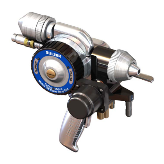
16E / 16E-H / 16E-P Spray Gun Product Description 16e_overview The 16E / 16E-H / 16E-P Spray Gun is a hand-held, wire-fed, combus- tion thermal spray gun. The spray gun is capable of using all com- monly available combustion fuel gases, with oxygen to produce flame sprayed coatings from Sulzer Metco metallizing wires. -
Page 15: Technical Data
“Hardware Selection” on page 26. 2. Wire sizes are listed in SI units for reference only. Wires for the 16E / 16E-H / 16E-P Spray Gun are supplied in standard US units or average wire gauge (AWG). MAN 96150 EN 01... -
Page 16: Component Descriptions
16E / 16E-H / 16E-P Spray Gun 2.2 Component Descriptions Drive Roll Carrier Wire Grip Mechanism Rear Wire Guide & Snubber Countershaft & Bearing Assembly Gas Head Assembly with Safety Handle & Valve Return Turbine & Speed Control Front End... -
Page 17: Gas Head Assembly
16E / 16E-H / 16E-P Spray Gun 2.2.1 Gas Head Assembly Supply hoses for air, oxygen and fuel gas connect to the hose block on the bottom of the gas head assembly. The gas head valve has three positions: •... -
Page 18: Turbine And Speed Control
The reduction ratio through the shafts and gears is not important, except to note that the 16E-H (high-speed) gun has a different turbine shaft and countershaft gear for higher range of feed rate. Additionally, the upper and lower drive rolls and gears can be changed to accommodate different gauges of wires. -
Page 19: Wire Grip Mechanism And Drive Roll Carrier
16E / 16E-H / 16E-P Spray Gun 2.2.5 Wire Grip Mechanism and Drive Roll Carrier The wire grip mechanism is a piston that forces the drive roll carrier to grip and start feeding the wire. The piston is actuated by the wire feed valve on the handle. -
Page 20: Principles Of Operation
16E / 16E-H / 16E-P Spray Gun 2.3 Principles of Operation Air Cap Nozzle Air Cap Body 127 mm (5”) Minimum 203 mm (8”) Maximum Air Envelope Atomized Spray Oxy- Wire Fuel Melting Wire Sprayed Material Characteristic luminous white Substrate... -
Page 21: Wire Feeding
16E / 16E-H / 16E-P Spray Gun 2.3.3 Wire Feeding When wire feeding is stopped, the wire will melt to a point inside the air cap just beyond the nozzle face. This is the ideal position of the wire to resume feeding or for lighting the gun. -
Page 22: Spray Gun Options
16E / 16E-H / 16E-P Spray Gun 2.4 Spray Gun Options 2.4.1 3XT Spray Gun Extensions 3XT-1 3XT-2 3XT-3 16e_3xt Spray gun extensions are available in 305 mm (1’), 610 mm (2’) and 915 mm (3’) lengths. The spray gun extension directly replaces the spray gun’s standard front end hardware and provides access to work-... -
Page 23: Auxiliary Equipment
16E / 16E-H / 16E-P Spray Gun 2.5 Auxiliary Equipment The 16E / 16E-H / 16E-P Spray Gun is the central component of the flame spray system. A complete flame spray system requires support- ing equipment to control compressed air, oxygen and fuel gas, and to feed the metalizing wire. - Page 24 16E / 16E-H / 16E-P Spray Gun 3GR Regulators 16e_3gr The 3GRA, 3GRO and 3GRP regulators are used to control the gas pressure for acetylene, oxygen and propane supply tanks, respec- tively. Refer to AUX 73498. 3GF Gas Flowmeter 16e_3gf The 3GF Gas Flowmeter controls and monitors the oxygen and fuel gas flow rates to the combustion thermal spraying system.
- Page 25 16E / 16E-H / 16E-P Spray Gun Spray Booth and Exhaust A fixed, permanent, indoor installation must include an exhaust hood or plenum, dust collector and a dedicated ventilation system. The installation might also include an acoustical spray booth and one or more manipulators such as a lathe, turntable or robot.
-
Page 26: Hardware Selection
16E / 16E-H / 16E-P Spray Gun 2.6 Hardware Selection The 16E / 16E-H / 16E-P Spray Guns are supplied, standard, with hardware that will meet the needs of the most common combustion wire. The specific hardware requirements are determined by combus- tion gas, wire type, wire size, and conditions of use. - Page 27 16E / 16E-H / 16E-P Spray Gun Siphon Plug / Nozzle / Air Cap Selection Chart Start-Stop Operation Babbit, Tin Normal Spraying Start-Stop Operation Low Melting-Point All Wire Aluminum & Zinc Alloys Alloys Siphon Non-Load Non-Load Non-Load Fuel Gas Wire Size...
- Page 28 16E / 16E-H / 16E-P Spray Gun Siphon Plug / Nozzle / Air Cap Selection Chart (Continued) Start-Stop Operation Babbit, Tin Normal Spraying Start-Stop Operation Low Melting-Point All Wire Aluminum & Zinc Alloys Alloys Siphon Non-Load Non-Load Non-Load Fuel Gas...
-
Page 29: Wire Guides, Drive Rolls And Drive Gears
16E / 16E-H / 16E-P Spray Gun 2.6.2 Wire Guides, Drive Rolls and Drive Gears Rear Upper Wire Drive Upper Drive Gear Guide Roll (Always 11E33) Front Wire Guide Rear Snubber Assembly Lower Lower Drive Drive Gear Roll 16e_guides_rolls_gears Selection of the wire guides, drive rolls and drive gears is determined by wire size. -
Page 30: Installation
16E / 16E-H / 16E-P Spray Gun Installation • See “Technical Data” on page 15 for facility compressed air and gas requirements. • Install and set up all auxiliary equipment in accordance with their instructions. (See “Auxiliary Equipment” on page 23.) •... -
Page 31: Connection
16E / 16E-H / 16E-P Spray Gun 3.3 Connection A typical 16E / 16E-H / 16E-P Spray Gun installation is shown in the following illustration. Wire 3GRO Oxygen 3GRA/3GRP Oxygen Fuel Gas Fuel Gas Fuel Compressed Air Supply 5k_connect •... - Page 32 16E / 16E-H / 16E-P Spray Gun • By convention, fuel gas hoses and fittings have left-hand threads. All other hoses and fittings are right-handed. 1. Turn on exhaust system and blow out all hoses into exhaust hood or plenum using dried/filtered compressed air. Make sure there is CAUTION no oil or dust in any of the hoses.
-
Page 33: Operation
16E / 16E-H / 16E-P Spray Gun Operation 4.1 Operating Controls Wire Speed Control Ring WIRE ON-OFF FEED LIGHT CLOSED Safety Valve 16e_operation Handle Gas Head Valve The gas head valve has an automatic safety return which closes the gas valve whenever the safety handle is released. The gas head valve has three positions: •... - Page 34 16E / 16E-H / 16E-P Spray Gun Safety Handle The safety handle keeps the gas head valve in the run or light position. Releasing it allows the gas head valve to close. Always start by mov- ing the gas head valve to the full run position; then, engage the safety INFO handle.
-
Page 35: Operating Procedures
16E / 16E-H / 16E-P Spray Gun 4.2 Operating Procedures • Ensure that system installation (“Installation” on page 30) is com- plete. • Be familiar with safety regulations under “Safety” on page 7 and always wear personal protective equipment (PPE). -
Page 36: Lighting
16E / 16E-H / 16E-P Spray Gun 4.2.2 Lighting There must always be wire in the nozzle when lighting the gun. If not, the gun may flash back through the rear wire guide. The wire should extend just past the front of the nozzle but not into the opening of the DANGER air cap. -
Page 37: Spraying
16E / 16E-H / 16E-P Spray Gun 4.2.3 Spraying Once the gun is lit and the turbine is up to speed, you may begin feed- ing wire and spraying. Make final adjustments to gas flows and pres- sures to obtain an optimal flame. -
Page 38: Troubleshooting
16E / 16E-H / 16E-P Spray Gun Troubleshooting Where troubleshooting procedures call for disassembly, inspection, assembly and replacement of parts, see “Maintenance” on page 41. 5.1 Avoiding Trouble • Most common problems are avoided by keeping the spray gun clean and lubricated. See “General Gun Care” on page 41. -
Page 39: Flashback / Backfire
16E / 16E-H / 16E-P Spray Gun 5.3 Flashback / Backfire Symptom: Gun will appear to go out or fail to light with a “pop” and will burn back in the siphon plug. Possible Causes: • Leak at the wire nozzle o-rings (see “Nozzles” on page 41) •... -
Page 40: Lighting Flow Check
16E / 16E-H / 16E-P Spray Gun 5.5 Lighting Flow Check Normal gas flow ranges with the gas head valve in the lighting position are given below. Flows lower than those shown indicate a possible blockage on a valve core bleeder port. Higher flows may mean a leaky valve seal. -
Page 41: Maintenance
The lubricant is required to ensure a proper seal and makes assembly easier. WARNING • Use only Krytox® on all o-rings. Do not use Sulzer Metco Valve- Damage! lube or Ringlube. Use only Krytox® on all o-rings in the 16E / 16E- •... -
Page 42: Gas Head Valve
6.5 Countershaft / Bearing Lubrication To lubricate a dry gun, use no more than 1 fluid oz (30 ml) of Sulzer Metco Gearlube to fill the gear case. To do this, remove the oil filler plug from the back of the central housing. Pour in the correct amount of Gearlube. -
Page 43: Hoses
16E / 16E-H / 16E-P Spray Gun 6.6 Hoses The following hose conditions will cause problems: • Obstructions in hoses will reduce the flow of oxygen and fuel gas and upset the flame balance. Blow out hoses with compressed air before connecting them. -
Page 44: Scheduled Maintenance
16E / 16E-H / 16E-P Spray Gun 6.7 Scheduled Maintenance This section provides information to help maximize service life and performance of the gun. Speed and load of gun, frequency of lighting, temperature at which gun operates affect service frequency of the spray gun. -
Page 45: Replacing Common Parts
16E / 16E-H / 16E-P Spray Gun 6.8 Replacing Common Parts This section describes how to remove and install parts that may wear out from normal use and parts that are configurable for different spray- ing applications. (See “Hardware Selection” on page 26.) For com- plete overhaul of the spray gun, see “Disassembly”... - Page 46 16E / 16E-H / 16E-P Spray Gun 5. Carefully press nozzle (23) into front of siphon plug (20). Be care- ful that nozzle o-rings are not twisted or torn and ensure that noz- zle shoulder is flush with front of siphon plug.
-
Page 47: Drive Rolls And Gears
16E / 16E-H / 16E-P Spray Gun 6.8.2 Drive Rolls and Gears Drive Roll Spanner 16e_rolls_gears Upper Drive Roll/Gear Removal/Disassembly 1. Press and turn pivot pin (105) clockwise and remove pivot pin. 2. Remove drive roll carrier (104) from spray gun. - Page 48 16E / 16E-H / 16E-P Spray Gun 3. Install screw (107) through bottom of drive roll carrier (104) and thread into drive roll axle (105). Tighten screw securely. 4. Install drive roll carrier (104) on spray gun. Make sure that piston rod of drive roll mechanism engages groove in drive roll carrier.
-
Page 49: Rear Wire Guide And Snubber
16E / 16E-H / 16E-P Spray Gun 6.8.3 Rear Wire Guide and Snubber 16e_snubber Removal/Disassembly 1. Remove set screw (9) and remove wire guide insert (1) (or strain relief assembly (11)). 2. Remove set screw (10) (from wire drive mechanism flange) and remove wire guide and snubber assembly (3-8) from central hous- ing (129). -
Page 50: Disassembly
16E / 16E-H / 16E-P Spray Gun 6.9 Disassembly Disassembly of the spray gun for service or overhaul can be done in any order except where noted. If a part must be removed for access, the prerequisite procedure is referenced. -
Page 51: Gas Head Assembly
16E / 16E-H / 16E-P Spray Gun 6.9.2 Gas Head Assembly The gas head assembly may be completely disassembled and ser- viced without removing it from the spray gun. To remove the gas head assembly, remove one screw (86) and two screws (91) securing the gas head assembly to the central housing (129). - Page 52 16E / 16E-H / 16E-P Spray Gun 3. Remove three screws (74) securing torsion ring cover (75) and remove torsion ring cover. 4. Remove screw (76) from end cap (77) and end cap pin (78). 5. Carefully rotate torsion ring (79) counterclockwise, slightly, increasing tension on torsion spring (81).
-
Page 53: Handle And Wire Feed Valve
16E / 16E-H / 16E-P Spray Gun 6.9.3 Handle and Wire Feed Valve 1. Remove screw (183) securing front handle to rear handle (182) and remove front handle. 16e_handle 2. Remove two screws (91) securing rear handle (182) and wire feed valve assembly to central housing (129). -
Page 54: Speed Control And Turbine
16E / 16E-H / 16E-P Spray Gun 6.9.4 Speed Control and Turbine Speed Control 1. Remove handle and wire feed valve (“Handle and Wire Feed Valve” on page 53) or wire feed valve shaft (“Accessing Lower Tur- bine Cover Screw” on page 53). - Page 55 16E / 16E-H / 16E-P Spray Gun Turbine 1. Remove oil plug (127) from back of central housing (129) and drain oil from spray gun. 16e_turbine_remove 2. Remove two screws (169) securing bearing cover (168) to gear cover (165) and remove bearing cover, gasket (170) and bearing follower (167).
-
Page 56: Countershaft, Drive Shaft And Bearings
16E / 16E-H / 16E-P Spray Gun 6.9.5 Countershaft, Drive Shaft and Bearings All bearings are press-fit onto shafts and seats. When removing a bearing, press only on the inner race. 1. Remove drive roll carrier, lower drive roll and lower drive gear. - Page 57 16E / 16E-H / 16E-P Spray Gun 5. Remove countershaft plug (157) from countershaft bearing retainer (160). 6. Hold countershaft assembly (9, 162 & 164) with glove or cloth and remove nut (158) from countershaft (164). Disassemble counter- shaft bearing retainer (160) and ball bearing (159) from counter- shaft assembly.
-
Page 58: Central Housing
The central housing assembly (129) should not be disassembled unless absolutely necessary to replace parts. The housing pump (130) requires critical alignment with the countershaft. This alignment can only be done properly by Sulzer Metco as part a factory overhaul. CAUTION Do not remove housing pump from central housing. -
Page 59: Assembly
16E / 16E-H / 16E-P Spray Gun 6.10 Assembly Before assembly, clean and inspect all parts. Replace damaged or worn parts. Do not clean o-rings with solvent. Apply a light coating of Krytox® to all o-rings. 6.10.1Countershaft, Drive Shaft and Bearings 1. - Page 60 16E / 16E-H / 16E-P Spray Gun 4. Install plug (171) and o-ring (94) in front of gear cover (156). 5. Apply gasket sealant (Loctite 587 Blue, or equivalent) to both sides of gasket (176). 6. Install gear cover (165) and gasket (176) on central housing (129) and secure with four screws (156).
-
Page 61: Speed Control And Turbine
16E / 16E-H / 16E-P Spray Gun 6.10.2Speed Control and Turbine Turbine 1. Install two o-rings (94 and 153) on turbine seal (152). 16e_turbine_assy 2. Slide turbine seal (152) onto turbine shaft (154) with smaller end of turbine seal near turbine shaft bushing. - Page 62 16E / 16E-H / 16E-P Spray Gun 8. Install turbine assembly (145-154) through central housing (129) and bearing in gear cover (165). 16e_turbine_remove 9. Install nut (158) on turbine shaft (154). 10. Apply gasket sealant (Loctite 587 Blue, or equivalent) to both sides of gasket (170).
- Page 63 16E / 16E-H / 16E-P Spray Gun Speed Control 1. Apply a light coating of Krytox® to inner threads of control ring (142) and outer threads of spider assembly (144). 16e_speedcont_assy 2. Assemble control ring (142), turbine cover (143) and spider assembly (144) with plastic brake shoe of spider assembly facing open side of turbine cover.
-
Page 64: Handle And Wire Feed Valve
16E / 16E-H / 16E-P Spray Gun 6.10.3Handle and Wire Feed Valve 1. Install o-ring (120) on valve shaft (177). 16e_handle 2. Apply a light coating of Krytox® to valve shaft (177) and install valve shaft and valve spring (178) in valve block (179). -
Page 65: Gas Head Assembly
16E / 16E-H / 16E-P Spray Gun 6.10.4Gas Head Assembly The gas head assembly may be assembled on or off the spray gun. To install the gas head assembly, install o-ring (134) on central housing (129) and secure gas head assembly to central housing with one screw (86) and two screws (91). - Page 66 16E / 16E-H / 16E-P Spray Gun 3. Install torsion spring (81) in flange of gas head subassembly (85). The spring’s longer free end fits in the slot of the flange and the shorter free end points downward. 4. Install spring bushing (80) on torsion spring (81).
- Page 67 16E / 16E-H / 16E-P Spray Gun 15. Install air plunger (95) in gas head subassembly (85). 16. Install one o-ring (99) each on two fuel gas and oxygen plungers (98). 17. Install fuel gas and oxygen plungers (98) in gas head subassem- bly (85).
-
Page 68: Wire Grip Mechanism
16E / 16E-H / 16E-P Spray Gun 6.10.5Wire Grip Mechanism 1. Install one o-ring (121) and two o-rings (120) on piston rod (116). 16e_wire_grip 2. Install o-ring (122) on piston (115). 3. Assemble piston (115) and piston rod (116) and secure with retain- ing ring (114). -
Page 69: Index
16E / 16E-H / 16E-P Spray Gun Index ........14 description ........15 dimensions ........50 disassembly Numerics countershaft, drive shaft, bearings ........22 14EWGM ....51 gas head assembly ..53 handle and wire feed valve ........ 14 description ... - Page 70 16E / 16E-H / 16E-P Spray Gun ......42 maintenance ........33 operation ......33 operating controls ...... 13 gas hoses and piping ....... 35 operating procedures ......15 gas requirements ........33 operation ......... 41 gun care ......22...
- Page 71 16E / 16E-H / 16E-P Spray Gun ....49 removal/replacement wire guides ........15 ........29 specifications selection ........34 speed control ........63 assembly ........ 18 description ......54 disassembly ......22 spray gun options ......... 37 spraying ........19...
- Page 72 16E / 16E-H / 16E-P Spray Gun This page intentionally left blank. MAN 96150 EN 01...
Need help?
Do you have a question about the 16E and is the answer not in the manual?
Questions and answers