Table of Contents
Advertisement
Quick Links
Advertisement
Table of Contents

Summary of Contents for Enapter EL2.0
- Page 1 EL2.0 Hydrogen Generator (35 bar) Installation Manual Rev. 08 – Mar 2020...
- Page 2 Version Document Title Release Date EL2.0 – Installation Manual 2020-03-18 EL 2.0 Installation Manual Rev. 08 March 2020 Enapter Srl Registered office: Via Lavoria 56/G 56040 Crespina (PI) Italy VAT no. 13404981006 All rights reserved. No parts of this manual may be reproduced, stored in a data retrieval system or transmitted by any means without the prior written permission of the issuer.
-
Page 3: Table Of Contents
Safety Area ................................24 EL2.0 – MANUAL OPERATION ......................26 ELECTROLYSER MONITORING TOOLS ..................27 Mobile Application ..............................27 Programming Ports ..............................27 TRANSPORT, MAINTENANCE AND RECYCLING ................ 28 Maintenance Routine .............................. 28 EL2.0 Installation Manual – Rev.08 Mar 2020... - Page 4 TECHNICAL SPECIFICATIONS ......................29 APPENDIX A: SYSTEM INTEGRATION ..................30 Management of Air Flows ............................30 Cabinet ..................................30 Gas and Water Connections ............................ 31 Electrical and Signals Connections .......................... 31 Hydrogen Storage ..............................31 EL2.0 Installation Manual – Rev.08 Mar 2020...
-
Page 5: Welcome
If you have any further question on the installation of the device, please contact the Enapter Srl Help Centre. Quote the system serial number when contacting us; you will find the serial number on the type plate placed on the rear side of the module. -
Page 6: Warnings And Hazards
Warns of physical damage to the product Do not open or dismantle Keep away from sources of heat and ignition No naked flames No smoking Minimum two persons required to handle the item Wear Personal Protective Equipment EL2.0 Installation Manual – Rev.08 Mar 2020... -
Page 7: General Safety Instructions
10. Never store the unit at temperatures below 2 °C with liquid inside the internal pipeline. This will cause irreversible damage to the electrolytic cells. 11. Only use demineralized water according to the specification stated in this manual. 12. Only operate the unit in a room with sufficient ventilation. EL2.0 Installation Manual – Rev.08 Mar 2020... -
Page 8: Hazards Description
✓ In the case of escaping gas, keep away and keep inflammable materials away. ✓ Prevent electrostatic charges. ✓ Ensure proper installation of the hydrogen supply. ✓ Check the hydrogen lines and connectors regularly for leak tightness. EL2.0 Installation Manual – Rev.08 Mar 2020... -
Page 9: Mechanical Hazards
EL2.0 – Installation Manual 2020-03-18 MECHANICAL HAZARDS As for the generic mechanical hazard that can occur during operations requiring the use of hand tools, Enapter Srl recommends wearing appropriate Personal Protective Equipment (PPE) and to use suitable tools. Operator’s protection When performing any operation, the operators must wear the appropriate PPE, such as cut resistant gloves, safety shoes, protective goggles etc. -
Page 10: Electrical Hazards
✓ Never use the product if any part of it has been immersed in water. WARNING! Any servicing, other than cleaning and user maintenance, must be performed by specialist personnel and with the power supply switched off. EL2.0 Installation Manual – Rev.08 Mar 2020... -
Page 11: Chemical Hazards
Do not flush to sewer. Dispose of the liquid in compliance with local and national regulations. WARNING! Observe all warnings and precautions listed in the accompanying Safety Material Data Sheet. EL2.0 Installation Manual – Rev.08 Mar 2020... -
Page 12: Thermal Hazards
The device has been designed for use in standard ambient conditions. The EL2.0 has not been designed for outdoor use and it is the user’s responsibility to protect the system and all its accessories against exposure to direct sunlight, rain, snow, lightening and the impact of seismic or hydrogeological events of particular intensity. -
Page 13: Unpacking
The unit must be returned according to the shipping instruction provided in this manual. In case there are any faulty or damaged parts, do not use them in order to not compromise the EL2.0 efficiency and safety. Address to an after-sales centre to replace faulty parts. -
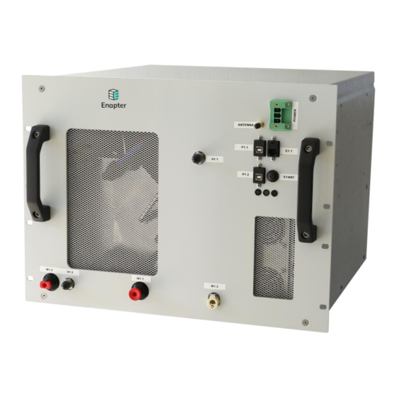
Page 14: Product Overview
W1.3 - Drain John Guest 6 mm quick coupling connector Power Antenna Fan Intake Programming Ports Start/Stop H1.1 Status LEDs Fan Intake W1.1 W1.2 W1.3 H1.2 References: Swagelok parts: www.swagelok.com John Guest parts: www.johnguest.com EL2.0 Installation Manual – Rev.08 Mar 2020... -
Page 15: El2.0 - Rear View
Document Title Release Date EL2.0 – Installation Manual 2020-03-18 EL2.0 - REAR VIEW The rear of the electrolyser features two hot air fan exhausts and a factory reset button. Fan Outlet Fan Outlet Reset EL2.0 Installation Manual – Rev.08 Mar 2020... -
Page 16: Assembly
5/8 combination wrench Stainless steel pipe cutter ¼” stainless steel hand tube bender Water connections: Plastic pipe cutter Electrical connections: Flat-blade screwdriver Crimping plier Cable section: 26 → 22 AWG Modules installation: Phillips head screwdriver EL2.0 Installation Manual – Rev.08 Mar 2020... -
Page 17: Accessories/Spare Parts
1/4” X 0,89 Water connections: 8 mm (outer diameter) LLDPE pipe 10 mm (outer diameter) LLDPE pipe Conditioning solution: KOH Potassium Hydroxide 99.99 % purity 40 g PC-EL communication Ethernet cable (LAN cable) EL2.0 Installation Manual – Rev.08 Mar 2020... -
Page 18: Gas And Water Connections
WARNING In order to supply the EL2.0 with clean DI water for refilling, water must be present in the electrolyser water refilling pipe at a pressure between 0.75 bar and 4 bar. If the EL2.0 does not detect the water pressure the system may not be able to refill itself. -
Page 19: Gas Connections
3. Pull on the tube to check it is secure. Test the system before use. 4. To disconnect, ensure the system is depressurized, push the collet square against the fitting. With the collet held in this position the tube can be removed. EL2.0 Installation Manual – Rev.08 Mar 2020... - Page 20 4. The solution starts flowing out immediately. Collect liquid in an appropriate container and place in a chemical waste container. Do not flush to sewer. Dispose of the liquid in compliance with local and national regulations. 5. To disconnect, push the button and pull the connector. EL2.0 Installation Manual – Rev.08 Mar 2020...
-
Page 21: Electrical Connections
GROUND CONNECTION The EL2.0 must be connected to ground to prevent user contact with dangerous voltage and to allow the correct functioning of the device. The grounding system must comply with the local and national regulations. -
Page 22: Commissioning
• Ensure Wi-Fi accessibility in the commissioning area Solution Included in Shipment The initial solution to fill the process tank inside the EL2.0 is shipped with the device, barring restrictions from the courier or local laws. Before powering on the device, please finish reading the rest of the manual. Carefully prepare your work area for the commissioning of the electrolyser. -
Page 23: First Filling Of The Process Tank
Notice: the pump draws up to 1 meter in height, keep the solution elevated so that filling is performed faster. 4. Plug the power cable into the EL2.0. Press the start/stop button and continue to apply pressure to it. Start supplying power to the EL2.0. Continue to hold the start/stop button down. -
Page 24: Installation
SAFETY AREA The operator of the EL2.0 must define a safety area which must be free of any source of ignition. This area should be located at a height of 3 metres above ground or higher. The lines from the ports H1.1, hydrogen output, H1.2, hydrogen purge and W1.1, O2 vent/overfilling must be led into the safety area. - Page 25 The customer may follow the recommendations of Enapter. This comprises the use of a standardized blowout pipe. The resulting explosive area, created by the released hydrogen, is cylindrical and has a height H of 8,8 m and a radius R of 1.3 m.
-
Page 26: El2.0 - Manual Operation
EL2.0 start-up and ramp If the conditioning solution inside the module is within the operating temperature range, the EL2.0 will first enter a 90 second hydration cycle, in which the process pump begins to cycle electrolyte around the module. Otherwise, a short heating and hydration cycle will take place first. -
Page 27: Electrolyser Monitoring Tools
P1.1 - This USB port acts as the primary board programming port that allows wired firmware upgrades for the EL board. These updates are performed by Enapter Srl. Please do not use it without previous agreement with the supplier. P1.2 - This USB port acts as the acquisition board programming port that allows wired firmware upgrades for the communication board. -
Page 28: Transport, Maintenance And Recycling
2 °C at any time. DISPOSAL The EL2.0 is a cradle to cradle product, please return it to Enapter at the end of life, where we will fully recycle the system. By ensuring this product is disposed of correctly, you will help to prevent potential negative consequences for the environment and human health. -
Page 29: Technical Specifications
Solve 40 g KOH in 4 L of demineralized water Max water consumption: 0.40 l/h Water input pressure: 0.75-4 bar Net Weight: 54 kg EL 2.0 Module EL 2.0 module dimensions (WxDxH): 483x490x354 mm (8U) Index of protection: IP22 EL2.0 Installation Manual – Rev.08 Mar 2020... -
Page 30: Appendix A: System Integration
APPENDIX A: SYSTEM INTEGRATION Since the EL2.0 hydrogen generator can be integrated into cabinets or other systems, the scope of this chapter is to provide technical information in order to allow a safe and proper integration. The user/integrator must comply with the manufacturer’s instructions described hereafter. -
Page 31: Gas And Water Connections
The liquid must be gathered in an appropriate container and disposed of in compliance with local and national regulations. ELECTRICAL AND SIGNALS CONNECTIONS The cabinet must be designed making sure there is enough space at the front of the EL2.0’s front plate to attach piping and the power supply cables. HYDROGEN STORAGE... - Page 32 Version Document Title Release Date EL2.0 – Installation Manual 2020-03-18 Enapter Srl Via Lavoria 56/G - 56040 Crespina (PI) – Italy Tel. +39 050 644 281 www.enapter.com EL2.0 Installation Manual – Rev.08 Mar 2020...
Need help?
Do you have a question about the EL2.0 and is the answer not in the manual?
Questions and answers