Table of Contents
Advertisement
Advertisement
Table of Contents

Subscribe to Our Youtube Channel
Summary of Contents for Secure PT3 Series
- Page 1 PT3 transducer range Technical reference manual BGX701-014-R03...
- Page 2 Copyright © 2020, SIHPL Page 2 of 40 BGX701-014-R03, User Manual for PT3 Transducers Public...
-
Page 3: Table Of Contents
Table of Contents Preface ............................5 Purpose and audience ..........................5 Abbreviations ..............................5 Related documentation ..........................5 Disclaimer ............................ 6 Important safety information ...................... 7 Safety during installing/ uninstalling and servicing ..................7 Disposal ................................. 7 Maintenance ..............................7 Introduction to three-phase transducers ................... - Page 4 11 Frequently asked questions (FAQs) ..................38 Page 4 of 40 BGX701-014-R03, User Manual for PT3 Transducers Public...
-
Page 5: Preface
1 Preface 1.1 Purpose and audience This manual provides the information necessary to configure, install, and use the PT3 range of transducers. The information in the manual is intended for use by technically qualified commissioning and operating personnel in power systems and process industries. Troubleshooting suggestions and answers to FAQs are included to assist in the installation and operation of the PT3 transducers. -
Page 6: Disclaimer
2 Disclaimer Secure Meters assumes no responsibility for damages caused to the PT3 transducer unit under following circumstances: 1. Improper maintenance/installation 2. Normal (or abnormal) wear and tear of insulation 3. Accidental contact with hazardous elements Page 6 of 40... -
Page 7: Important Safety Information
3 Important safety information Local best practice and regulatory stipulations must always be observed. In addition, safety precautions recommended for installation of electrical equipment should be strictly adhered to. Transducers should be installed by trained personnel only. The following symbols have been used in this document or appear on the product. Risk of electric Caution Alternating current... -
Page 8: Introduction To Three-Phase Transducers
4 Introduction to three-phase transducers The PT3 transducer is suitable for measuring, monitoring and analysing three-phase industrial and supply applications. It is available with up to four analogue outputs and can accurately measure electrical quantities such as current, voltage, active power, reactive power and power factor by converting them into proportional DC current or voltage analogue signals (For e.g. -
Page 9: Physical Features
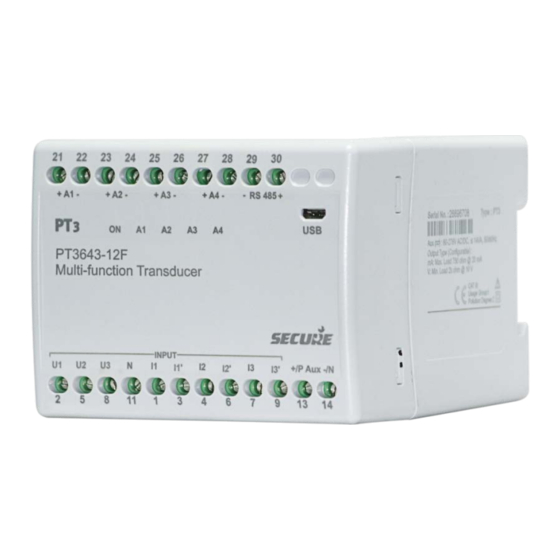
4.1 Physical features The figure below provides an illustrated reference to the main parts of the PT3 transducer device. Figure 1: PT3 transducer physical features Note: A terminal will be marked as ‘NC’ when it is not available for use. NC refers to a non-connected terminal. 4.2 Communication ports (RS-485 and USB) The PT3 is equipped with a micro USB port. -
Page 10: Technical Specifications
5 Technical specifications Environmental and safety specifications II (double insulation) EN 61010-1 Protection class Pollution degree Protection enclosure - IP 40, terminals and USB - IP 20 Ingress protection (EN 60529) ° ° Operating range C to + 55 Temperature Limit range for °... - Page 11 (Applicable for accuracy class 1.0 and 0.5) 0-1 mA and 0-2 mA (Applicable for accuracy class 1.0) -5 to +5 V and -10 to +10 V type (Applicable for accuracy class 1.0, 0.5 and 0.2) current Input (I ) current 1 to 5 A Measuring current range 0 to 150% I...
- Page 12 -1 to +1 mA and -2 to +2 mA, (Applicable for accuracy class 1.0) -5 to +5 V and -10 to +10 V V type (Applicable for accuracy class 1.0, 0.5 and 0.2) Scale factor 0.5 to 1.5 (active power at unity power factor) 0.3 to 1 (reactive power at reactive power factor >0.8 or unity) Input voltage (U...
- Page 13 (Applicable for accuracy class 1.0, 0.5 and 0.2) -5 to +5 mA (Applicable for accuracy class 1.0 and 0.5) -1 to +1 mA and -2 to +2 (Applicable for accuracy class 1.0) V type -5 to +5 V and -10 to +10 V (Applicable for accuracy class 1.0, 0.5 and 0.2) Input voltage (U...
- Page 14 Measurement range 45 Hz to 55 Hz (on 50 Hz), or 55 Hz to 65 Hz (on 60 Hz) Output curve mA type -20 to +20 mA, 4-20mA and -10 to +10 mA (Applicable for accuracy class 1.0, 0.5 and 0.2) -5 to +5 mA (Applicable for accuracy class 1.0 and 0.5)
-
Page 15: Pt3 Output Signals
Response time At 5 cycles measurement ≥100 ms to ≤ 220 ms Ripple < 0.4% peak to peak, at 20 mA Mechanical specifications 100 mm x 75 mm x 105 mm Product dimensions (W x H x D) Weight 0.7 kg (approx.) Material Flame-retardant polycarbonate (PC-FR), UL94 V-0 Mounting... - Page 16 zero) Example 4-6-20 mA Example (-10)-0-10 mA Example 0-5-10 mA corresponding to 0-8-12 kV corresponding to (-100) -0-100 corresponding to (-100) -0-100 kW Figure 2: PT3 transducer output curves Page 16 of 40 BGX701-014-R03, User Manual for PT3 Transducers Public...
-
Page 17: Configuring Pt3 Transducers
6 Configuring PT3 transducers Configuration means setting up the programmable features in a device, in order to make it suitable for a particular application. To configure PT3 transducers, you must have the latest version of ConfigView software installed on your PC or laptop device. This software may be downloaded free of charge from our website: www.securemeters.com. -
Page 18: Procedure To Configure Pt3 In Offline Mode
Note: Please refer the ConfigView user manual for detailed settings that can be configured in the PT3 transducers. 6.2 Procedure to configure PT3 in Offline mode In this mode, a configuration file is generated in ConfigView and saved in the computer or laptop. This configuration can be transferred to the transducer device by establishing a physical connection at any later time. - Page 19 To print/export the label from ConfigView, do the following: • Click the icon in the toolbar. • The printer settings can be adjusted, or the file can be exported in Word, Excel or PDF formats. • To export the file, click the icon in the Print screen toolbar.
-
Page 20: Installing Pt3 Transducers
7 Installing PT3 transducers 7.1 PT3 transducer dimensional details The overall dimensions of PT3 transducers are shown below. Figure 6: PT3 transducer dimensions 7.2 Mounting the PT3 transducer on a DIN rail To mount the PT3 transducer on a DIN rail, hook one edge of the rail with the top edge of the cut out located at the rear of the device. -
Page 21: Demounting The Pt3 Transducer
Check that the device is securely fixed. Figure 8: PT3 transducer mounted on DIN rail 7.3 Demounting the PT3 transducer To remove or reposition the transducer device, lever up the release clip with a screwdriver, and then lower the device off and away from the rail. Figure 9: Demounting the PT3 transducer Page 21 of 40 BGX701-014-R03, User Manual for PT3 Transducers... - Page 22 Note: To prevent damage to the screw heads when tightening the screws, it is highly recommended to use a torque controlled screw driver with appropriate bit size. A recommended screw driver with bit size is illustrated below. Page 22 of 40 BGX701-014-R03, User Manual for PT3 Transducers Public...
-
Page 23: Pt3 Network Connections
8 PT3 network connections Physical connections to the PT3 with the network are made on the front of the transducer. The connections are: measuring voltages, measuring currents, analogue outputs, auxiliary power and connections to RS-485 communication module. The connections must be performed in accordance with the measurement method and wiring settings configured in the transducer. - Page 24 Four-wire system, three element balanced load (U1-I1) Direct connected Direct connected voltage and external current transformer External voltage and current transformers Three-wire system, two element asymmetric load (D) Direct connected Direct connected voltages and external current transformers Page 24 of 40 BGX701-014-R03, User Manual for PT3 Transducers Public...
- Page 25 Two external voltage and current Three external voltage transformers and transformers two current transformers Three-wire system, two element balanced load (U12-U23-L1) Direct connected Direct connected voltages and external current transformer External voltages and current transformers Page 25 of 40 BGX701-014-R03, User Manual for PT3 Transducers Public...
- Page 26 Three-wire system, two element balanced system (U12-L1) Direct connected Direct connected voltage and external current transformer External voltage and current transformers Three-wire system, two element balanced system (U23-L1) Direct connected Direct connected voltage and external current transformer Page 26 of 40 BGX701-014-R03, User Manual for PT3 Transducers Public...
- Page 27 External voltage and current transformers Three-wire system, two element balanced system (U31-L1) Direct connected Direct connected voltage and external current transformer External voltage and current transformers Page 27 of 40 BGX701-014-R03, User Manual for PT3 Transducers Public...
- Page 28 Single phase system Direct connected Direct connected voltage and external current transformer External voltage and current transformers Note: Please connect a 750 ohm resistor across any unused analogue outputs. Page 28 of 40 BGX701-014-R03, User Manual for PT3 Transducers Public...
-
Page 29: Modbus Mapping
9 Modbus mapping 9.1 Introduction The PT3 multi-function transducer variant is included with an RS-485 port to enable reading of instantaneous parameters such as line voltages, current and power over Modbus protocol. The data stored in various holding registers can be read from the transducer device at any given time by sending a request through a supported controller device. -
Page 30: Modbus Function Codes
9.3.5 Modbus function codes The transducer supports the function code ‘03’ to read holding registers. To read parameter values stored in holding registers, a controller device sends a request to the slave device (transducer). This request specifies the start register address and the number of registers to be read out. The start register is numbered from zero (for example, 40001 = zero, 40002 =one, etc.). - Page 31 9.3.6.2 Standard registers (For instantaneous parameters) All calculated values are represented as two consecutive Modbus registers. The value of a quantity is represented as a single precision floating point number according to IEEE 754, in SI unit. Register address Size (in bytes) Parameter Format (in decimal)
-
Page 32: Supported Reading Parameters For Different Pt3 Network Connections
9.4 Supported reading parameters for different PT3 network connections The following table shows a list of parameters that can be read for each network type. Values of parameters not supported by a specific network can be read but may not be displayed correctly. Such parameters are not marked with any symbol in the table. -
Page 33: Reading Holding Registers
Apparent Power (Ph2) Apparent Power (Ph3) Power Factor (Ph1) Power Factor (Ph2) Power Factor (Ph3) Power Factor (angle 1) Power Factor (angle 2) Power Factor (angle 3) System Voltage ... - Page 34 The following table shows the Read Holding Registers request and response packet formats, and an example transaction. Read Register Request Packet Read Register Response Packet (Controller to Transducer) (Transducer to Controller) Unit ID/Slave Address (1 byte) Unit ID/Slave Address (1 byte) 03 -Function code (1 byte) 03 (Function Code)
- Page 35 Sr. No. Error description Error code Illegal function Illegal address Illegal frame size CRC fail Example: Error response when read invalid address The transducer is configured as a Modbus slave device, with a slave address of 240. If the Master requests to read holding registers 42020, which is the invalid address.
-
Page 36: Troubleshooting
10 Troubleshooting Problem Possible cause Check The transducer does not Auxiliary power Check the auxiliary supply. The ON LED on the front panel seem to be working. may not be glows green when the unit is powered by the auxiliary connected or supply. - Page 37 connected. The current The output level is about Check the selection for Current Secondary. input one fifth or five times the configuration Current and derived power values will be reported low if a expected value, although secondary may CT with 1 A secondary is connected to inputs set for 5 A. the input signal is healthy, be set They will be reported high if the condition is reversed.
- Page 38 11 Frequently asked questions (FAQs) When installing a PT3 This is a very flexible process, which can be done in a number of ways, but transducer, what is the best the simplest sequence is as follows: order in which to do things? 1.
- Page 39 lower down in the output range. What does a breakpoint on Without a breakpoint, the transfer characteristic between input and output is a transfer characteristic do? purely linear. A breakpoint allows the curve to be adjusted for non-linear characteristics. For example, this can be done to apply a correction for a deficiency in a sensor, or to ‘roll off’...
- Page 40 www.securemeters.com...
Need help?
Do you have a question about the PT3 Series and is the answer not in the manual?
Questions and answers