Table of Contents
Advertisement
Quick Links
AS-Interface
X20IF10A1-1 user's
manual and data sheet
Version: 2.00 (February 2018)
Model no.: MAX20IF10A1-1-ENG
Translation of the original manual
All values in this manual are current as of its publication. We reserve the right to change the contents of this manual
without notice. B&R Industrial Automation GmbH is not liable for technical/editorial errors or incomplete information
in this manual. In addition, B&R Industrial Automation GmbH shall not be liable for incidental or consequential
damages in connection with or arising from the furnishing, performance or use of this material. The software names,
hardware names and trademarks used in this document are registered by their respective companies.
Advertisement
Table of Contents

Related Manuals for B&R X20IF10A1-1

Summary of Contents for B&R X20IF10A1-1
- Page 1 AS-Interface X20IF10A1-1 user's manual and data sheet Version: 2.00 (February 2018) Model no.: MAX20IF10A1-1-ENG Translation of the original manual All values in this manual are current as of its publication. We reserve the right to change the contents of this manual without notice.
-
Page 2: Table Of Contents
4 The AS-Interface......................8 4.1 EDS device description file..........................8 4.2 Settings in Automation Studio........................9 4.2.1 Creating an Automation Studio project..................... 9 4.2.2 Adding and configuring the interface module..................10 4.3 Slave addressing............................14 AS-Interface X20IF10A1-1 user's manual and data sheet 2.00... -
Page 3: General Information
A 2-conductor cable is used instead, which transfers both power and information at the same time. • AS-Interface master • Electrically isolated • 4-pin bus connector AS-Interface X20IF10A1-1 user's manual and data sheet 2.00... -
Page 4: Order Data
1x terminal block TB704 sep- arately! Required accessories Terminal blocks 0TB704.9 Accessory terminal block, 4-pin, screw clamps 2.5 mm² 0TB704.91 Accessory terminal block, 4-pin, cage clamps 2.5 mm² Table 1: X20IF10A1-1 - Order data AS-Interface X20IF10A1-1 user's manual and data sheet 2.00... -
Page 5: Technical Data
Protection per EN 60529 IP20 Environmental conditions Temperature Operation Horizontal installation -25 to 60°C Vertical installation -25 to 50°C Derating Storage -40 to 85°C Transport -40 to 85°C Table 2: X20IF10A1-1 - Technical data AS-Interface X20IF10A1-1 user's manual and data sheet 2.00... -
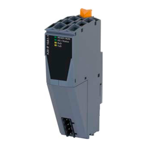
Page 6: Operating And Connection Elements
Table 2: X20IF10A1-1 - Technical data 3.2 Operating and connection elements LED status indicators IF1 - AS-Interface 3.3 AS-Interface (IF1) Interface Pinout Terminal Explanation ASi+ ASi+ ASi- ASi- 4-pin male multipoint connector AS-Interface X20IF10A1-1 user's manual and data sheet 2.00... -
Page 7: Usage With Powerlink Bus Controllers
The module comes with preinstalled firmware. The firmware is a component of Automation Studio. The module is updated to this version automatically. To update the firmware contained in Automation Studio, the hardware must be upgraded (see "Project manage- ment / Workspace / Upgrades" in Automation Help). AS-Interface X20IF10A1-1 user's manual and data sheet 2.00... -
Page 8: The As-Interface
Storage of the address or extended ID code 1 Permanent memory Volatile memory Peripheral error state occurred No error occurred Error occurred Undefined Error occurred while reading a permanent memory area. No error occurred Error occurred AS-Interface X20IF10A1-1 user's manual and data sheet 2.00... -
Page 9: Settings In Automation Studio
● Select the hardware in the next step if "Define a new hardware configuration manually" was selected. In order to simplify the search, different filters can be set in the Hardware Catalog. Lastly, highlight the required hardware create the Automation Studio project by clicking on "Finish". AS-Interface X20IF10A1-1 user's manual and data sheet 2.00... -
Page 10: Adding And Configuring The Interface Module
● The module is added to the project via drag-and-drop or by double-clicking on the interface card. ● AS-i slaves from the Hardware Catalog containing the required AS-i profile can now be connected to the AS-i master. AS-Interface X20IF10A1-1 user's manual and data sheet 2.00... - Page 11 Input or output type Length Number of bytes inserted (IB, QB, IW or QW). Address Input or output data offset address The input and output address table can also be exported as a CSV file. AS-Interface X20IF10A1-1 user's manual and data sheet 2.00...
- Page 12 • Auto address assignment - If enabled, the master assigns a slave the address of a missing slave if it has an identical I/O, ID, ID1 and ID2 code and address 0. — Overwrite configuration database If enabled, the master overwrites the database when receiving configuration commands from the interface. AS-Interface X20IF10A1-1 user's manual and data sheet 2.00...
- Page 13 "EDS device description file" on page Signal configuration The name and data type of the I/O data point can be adjusted here. The names can also be changed with the master (see "Process data" on page AS-Interface X20IF10A1-1 user's manual and data sheet 2.00...
-
Page 14: Slave Addressing
AS-interface of the master and selecting → Additional functions → Set station address. First, the slave to be addressed is selected and the desired new address is specified. A new address can be assigned using "Set address". AS-Interface X20IF10A1-1 user's manual and data sheet 2.00...
Need help?
Do you have a question about the X20IF10A1-1 and is the answer not in the manual?
Questions and answers