
Related Manuals for Humbaur HTK Series

Summary of Contents for Humbaur HTK Series
- Page 1 Operating Instructions Construction transporter HTK three-way tipper (10 t - 18 t) humbaur.com 10000 Series...
- Page 5 Ensure that the operating manual is vehicle and its modules. work. Only with this information is it included when the trailer is sold, for Humbaur GmbH accepts no liability for possible to avoid errors and ensure fault- example. any damage, injuries or malfunctions free operation.
- Page 6 Contents of this operating manual Identification Dimensions, weights and performance data can be found in the trailer's registra- tion documents. Vehicle type Version Three-way tipper, tandem (total weight 10.5 t) HTK 104522 Three-way tipper, tandem (total weight 10.5 t) HTK 105024 Three-way tipper, tandem (total weight 10.5 t) HTK 105524...
- Page 7 Contents of this operating manual Keyword index 4 Operation of the chassis 7 Inspection, care and Use the keyword index, starting on page 5, to search for specific topics. maintenance The chapter entitled "Operation of the chassis", starting on page 77, provides In the chapter "Inspection, care and 1 Safety everything you need to know about the...
- Page 8 Contents of this operating manual...
- Page 9 Index Operation body Lubricating grease Operation of the chassis Contact Safety Humbaur Service Partners Access aids Troubleshooting Parts logistics Address Check when parking Technical customer service Manufacturer Clean Duo-Matic coupling Coupling Replacement parts Cleaning Hydraulic line Service Cleaning alloy wheels...
- Page 10 Axle/wheel maintenance Lashing points Certificate of general inspection/safety Lettering assessment Fixings Lettering work Support equipment maintenance Fixings, cable clips Licence plate light Draining the compressed air tank Folding support Lighting Driving off Form-fit load securing Filament lamps Driving on ramp planks Friction-lock load securing Limit light Front platform gate...
- Page 11 Draw pipe height adjustment system Compressed air tank Front platform gate locks Draw pipe height adjustment system Operating manual instructions Front side central locking system Electrical system Operating platform gate attachments Pivot hinge Licence plate light "standard" Operating platform gates Rear side central locking system Lighting Operating ramp planks...
- Page 12 Pin couplings Safety Spare wheel transport Plug connections (standard) Safety instructions Spindle support identification Plug connections 2x7-pin (optional) Screw parking brake Spring-loaded parking brake Pressure level Securing loading platform Emergency release Prohibition signs Tilting bearing Stability Putting lifting device into position Securing the load Stanchions (load securing) Covering net...
- Page 13 Toolbox Unloading Changing 304 Track width Traction test Proper Trailer Reasonably foreseeable misuse Disposal Using steel grate attachments Securing Using support frame Taking out of operation Trailer materials Vehicle identification numbers Troubleshooting versions of towing eye Axles Brake system Electrical system Hydraulics/electro-hydraulic unit Warning signs Loading/driving performance...
- Page 15 MACHT’S MÖGLICH Safety...
- Page 16 – Operation only in the range of the the HUMBAUR vehicle itself or to other total permitted payload property. HUMBAUR vehicles/bodies –...
- Page 17 – Loading with exceeded payload – Unauthorised maintenance/repair of Humbaur GmbH – Exceeding the maximum permissible safety-relevant components which Mercedesring 1 axle/bearing/trailing load must only be maintained or repaired...
- Page 18 620.00127 Fig. 1 Warning panel on the trailer In the event of non-compliance with any of the above or failure to provide the results of a traction test, any warranty claims made against Humbaur GmbH will be invalidated. 12 Safety...
- Page 19 – The original parts or the conversion parts/accessories approved by – approvals have been granted by Humbaur GmbH being replaced by public authorities. other components. – Subsequent alterations have been made to the trailer (e.g. new holes made in the frame or existing bore holes enlarged).
- Page 20 For this reason, in spite of the most Unauthorised modifications to the trailer or built- varied types of machining and coating, it is on accessories not approved by Humbaur GmbH subject to natural, weather-dependent stretching will invalidate the warranty. Non-observance of or shrinkage, which can lead to distortions.
- Page 21 Defects that can be traced back to the conse- If the service intervals are not observed, quence of a repair carried out by a non-approved including those for Humbaur-fitted parts such as workshop. axle, brake, overrunning equipment, hydraulic Defects that can be traced back to structural systems, etc.
- Page 22 Personnel qualifications HUMBAUR vehicles and bodies and their operating components may only be used and maintained by personnel who have received instruction with regard to: – This operating manual – The trailer with the associated towing vehicle – The suppliers' operating and maintenance manuals –...
- Page 23 Check, adjust and secure before every journey Sources of danger It is essential that you are aware of the – Excessive steering during – Standing under a raised loading following source of danger: manoeuvring. bridge. – Overloading of the trailer, axes and –...
- Page 24 Check, adjust and secure before every journey In the chassis frame area – Drain the compressed air tanks Around the vehicle body Important general information: – Check the licence plate and signs Close and secure all vehicle body components, such as: –...
- Page 25 Safety instructions Signal words Text emphasis General mandatory sign. DANGER Indicates information that has to You will find the following symbols in be heeded and complied with for Indicates an immediate danger front of some lines or paragraphs in the safe use.
- Page 26 Safety instructions Warning signs used The following warning signs can be used Risk of crushing injuries! Risk of chemical burns! in this manual and on the product. For limbs such as: Escaping battery acid. hands/fingers/feet Heed these warning signs and proceed with particular caution.
- Page 27 Personal protective equipment/rules and prohibited activities Personal protective equipment Instruction signs Wear the prescribed personal protective Keep to and heed the following rules and equipment (PPE) for all the work prompts for all the work described in this described in this manual. manual.
- Page 28 Personal protective equipment/rules and prohibited activities Prohibition signs Other important pictograms Heed these prohibited activities. Observe the following pictograms for correct disposal as well as first aid in the Climbing up prohibited. case of emergency. Reaching in prohibited. Problem waste! Disposal with domestic waste not allowed.
- Page 29 MACHT’S MÖGLICH General Information...
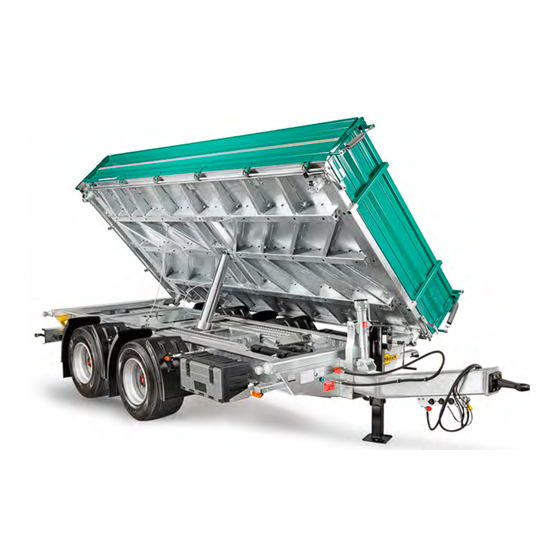
- Page 30 HTK product description HTK 10.5 t Fig. 1 Tube drawbar with towing eye Compressed air connect.: Supply, brake Spindle support Screw parking brake, manual Service brake release valve Axles/wheels Side platform gates Platform gate lifting spring Front platform gate 10 Height setting device 11 Central locking system 12 Front platform gate locks 13 Rear platform gate...
- Page 31 Basic components HTK 13.6 t I - 004 Fig. 4 Side view I - 005 Fig. 5 tilted: to the side and rear General Information 25...
- Page 32 Basic components HTK 18 t I - 006 Fig. 6 Front view I - 007 Fig. 7 tilted: to the side and rear 26 General Information...
- Page 33 Basic components Specifications of HTK three-way tipper The HTK is a construction transporter The platform walls to the side and the with a height-adjustable tube drawbar. rear feature a central locking system for the pendulum mode. The tube drawbar is supported in the front with a reinforced spindle support for up to 12 t.
- Page 34 Basic components HTK, special design The HTK three-way tipper can be delivered with various structures on request. Here are a few examples: I-048 Fig. 8 HTK with stationary ramps Ramps, split 28 General Information...
- Page 35 Basic components HTK as a agricultural trailer e.g. for silo transport I-049 Fig. 9 HTK with steel grate body and roller curtains Roller curtains Steel grate body Access platform General Information 29...
- Page 36 Various models/accessories Ramp planks, retracted Shut-off cable for loading bridge Rotatable towing eye I - 008 I-010 I-009 Fig. 10 Ramp plank bays in chassis Fig. 12 Loading bridge tilted to the side Fig. 14 D=40 mm or D=50 mm Platform gate lifting springs Ramp plank safety device Covering net safety device...
- Page 37 Various models/accessories Covering net Steel grate attachment, low Dosing slider with pipe outlet I-050 I - 055 I-014 Fig. 16 Loading platform with covering net Fig. 18 With dual lifting springs Fig. 20 Rear side Arrangement: Centre or right/left Support frame Steel grate attachment, 1 m high Dosing slider I-013...
- Page 38 Various models/accessories Platform gate attachment Front wall attachment Spindle support I-017 I - 036 I-015 Fig. 22 Steel Fig. 24 Steel Fig. 26 Support equipment, front side Steel grate front wall attachment Support foot, hydraulic Platform gate attachment I-044 I - 037 I-052 Fig.
- Page 39 Various models/accessories Swivel support Spare wheel Spare wheel I-054 I-018 I-043 Fig. 28 Swivelable support equipment for Fig. 30 Spare wheel holder on the front wall Fig. 32 Loose spare wheel on the loading through-load option platform Access ladder Raise/lower system Raise/lower system I-016 I-021...
- Page 40 Various models/accessories Securing the load Swinging doors Toolbox I-026 I-022 I-023 Fig. 34 Lashing ring, can retract in pocket Fig. 36 Rear platform gate as swinging door Fig. 38 On the side, under chassis Securing the load Securing the load Toolbox I-025 I-024...
- Page 41 Various models/accessories Safety chain Service support Front platform wall, foldable I-027 I-031 I-031 I - 040 I - 040 Fig. 40 On rear platform gate Fig. 42 Under loading bridge Fig. 44 Through-load option Platform gate door stay Side posts on loading platform Draw pipe height adjustment I-030 I - 041...
- Page 42 Various models/accessories Folding support Working light Roller curtains I-019 I-046 I-046 I-047 Fig. 46 At rear, manual Fig. 48 Rear side, single, double Fig. 50 Roller curtains on steel grate body Rotating light LED lights Dual lifting springs I-045 I-051 I-053 Fig.
- Page 43 Various models/accessories Pedestal with ladder I-056 Fig. 52 On the front platform gate Lashing pocket cover I-057 Fig. 53 Lashing pockets covered General Information 37...
- Page 44 Vehicle identification numbers (VIN) VIN - engraved Item 10-17 Nameplate Nameplate/weight specifications Front side, rack Item Explanation 1-3= International code for Humbaur GmbH 4-9= Filler character chosen by manufacturer 10-17= Sequential numbering Tab. 1 Example - VIN number 38 General Information...
- Page 45 Support equipment identification Spindle support For A nameplate is attached to the Manufacturer of the spindle support: spindle support to identify it. haacon hebetechnik gmbh Josef- Haamann-Strasse 6 If you have any questions about D-97896 Freudenberg the spindle support, specify the factory no.
- Page 46 EC declaration of conformity Humbaur GmbH hereby confirms compliance with all rel- evant EC guidelines for the certification and safe operation of HTK trailers. You can separately request an EC Dec- laration of Conformity from us. I - 035 Fig. 57 EC declaration of conformity...
- Page 47 MACHT’S MÖGLICH Operation...
- Page 48 General Towing eye NOTICE Exceeding the permissible tilt angle max. 20° When driving over slopes and descents, the maximum permissible inclination angle of the towing eye and pin coupling max. 20° can be exceeded. Trailer, towing eye, and pin coupling can be damaged.
- Page 49 Stability NOTICE WARNING Loss of stability during loading and Driving the trailer unloading When driving the trailer or if the The rear axle and the chassis can get load distribution is not uniform, damaged/overloaded. the trailer can tip to the side - risk of striking/crushing! ...
- Page 50 Stability B - 004 Fig. 4 Driving the trailer The warning panels on the ramp WARNING planks must be observed and adhered to! Overloading ramp planks The ramp planks can get deformed. The vehicle can fall/tip over - risk B - 036 of striking/crushing! Fig.
- Page 51 Stability B - 037 B - 037 B - 038 Fig. 6 Ramp planks with securing hooks Fig. 8 Ramp planks with securing hooks Fig. 10 Ramp planks with retaining pin B - 057 B - 035 B - 005 Fig.
- Page 52 Loading and unloading Loading and unloading vehicles Procedure: WARNING Place the trailer on firm ground to Limited visibility prevent it from sinking in or toppling When driving in reverse, over. persons could be overlooked Secure the trailer from rolling away. and run over.
- Page 53 Loading and unloading Loading and unloading WARNING WARNING Entering loading platform Shifted loading goods There is a risk of falling when There is an increased danger of injury climbing on/off the loading during loading and unloading. platform/the chassis, over mud This can result in cutting and crushing guards, side guards, tube injuries.
- Page 54 Loading and unloading WARNING Loading/load-securing elements on the loading platform The loading platform can be misaligned with loading goods, squared timber, ratchet straps and pallets - risk of tripping! Make sure there is enough light on the B - 007 B - 008 loading platform.
- Page 55 Loading and unloading B - 009 Fig. 16 Tilting loading platform/danger areas Procedure: Also make sure that traffic is not Keep personnel away from the danger Never walk on the loading platform or blocked. zone. chassis during the tilting process. ...
- Page 56 Loading and unloading After loading and unloading The body must be completely WARNING Prerequisites for safe driving closed and secured during the with trailer: drive. Driving with unsecured ramp planks/ open platform gates, flaps The load must be properly Comply with the total weight, axle lashed/secured.
- Page 57 Load distribution/max. weight Permissible weights and load distribution B - 010 Fig. 17 Load definition S Drawbar load The maximum payload of the trailer can A1 Axle load - 1st axle only be reached if the overall load centre A2 Axle load - 2nd axle of the load is within the permissible range.
- Page 58 Load distribution/max. weight ca. 2,37 m (104522) ca. 2,79 m (105024) ca. 3,29 m (105524) B - 011 Fig. 19 Example 10 t - Load distribution plan Distance of the load centre of gravity from the loading platform front wall Centre of gravity of the load Loads Max.
- Page 59 Load distribution/max. weight ca. 2,85 m (135024) ca. 3,10 m (135524) B - 012 Fig. 20 Example 13 t - Load distribution plan Distance of the load centre of gravity from the loading platform front wall Centre of gravity of the load Loads Max.
- Page 60 Load distribution/max. weight ca. 2,85 m (185024) ca. 3,10 m (185524) B - 013 Fig. 21 Example 18 t - Load distribution plan Distance of the load centre of gravity from the loading platform front wall Centre of gravity of the load Loads Max.
- Page 61 Connection element: Towing eye General In order to connect the trailer to a towing machine, a towing eye is attached to the tube drawbar. DANGER Damaged connection element The trailer could detach from the towing machine during the drive - risk of accident! B - 014 Fig.
- Page 62 Connection element: Towing eye Possible Versions of towing eye Do regular visual inspections of the towing eye (see page 269). Only allow a qualified specialist to carry out repair work on the towing eye. Never do welding or adjustment work yourself on the towing eye.
- Page 63 Connection element: Towing eye Rotatable towing eye (option) The rotatable towing eye can be used for coupling varieties on the towing machine with diameter D40 mm or D50 mm. The rotatable towing eye is secured with the following mounting elements: –...
- Page 64 Connection element: Towing eye Releasing Rotating B - 020 B - 022 B - 021 Fig. 29 Towing eye locked at bottom Fig. 31 Rotating the towing eye Fig. 30 Removing fastening bolt Wing nut Fastening bolt Spacer sleeve Bracket Shim rest ...
- Page 65 Connection element: Towing eye Securing Securing towing eye (D50) B - 023 B - 024 B - 025 Fig. 32 Towing eye D50 locked at bottom Fig. 33 Securing the towing eye D50 at Fig. 34 Towing eye D50 secured bottom Fastening bolt Bracket...
- Page 66 Connection element: Towing eye Securing towing eye (D40) B - 026 B - 027 B - 028 Fig. 35 Towing eye D40 locked at top Fig. 36 Securing towing eye (D40) Fig. 37 Towing eye D40 secured Fastening bolt Wing nut Bracket Spacer sleeve Towing eye (D40)
- Page 67 Connection element: Towing eye Incorrectly secured towing eyes NOTICE Incorrectly securing the towing eye The towing eye bushing may be damaged - premature wear. Secure the towing eye properly. Insert the fastening bolt only in the pockets of the bracket - not directly on the towing eye.
- Page 68 Connecting trailer to the towing vehicle/detaching from the towing vehicle Connecting the towing machine to the trailer and detaching the trailer from the towing vehicle are two of the most dangerous procedures when operating Make sure danger area Never allow a trailer to run the trailer.
- Page 69 Connecting trailer to the towing vehicle/detaching from the towing vehicle CAUTION Pin coupling is difficult to access Hand/fingers can be crushed when operating the pin coupling. You could hit your head. Before operating the pin coupling, check that there is enough free space for safe operation.
- Page 70 Coupling Available versions of Pin couplings B - 032 B - 033 B - 034 Fig. 41 Manual Fig. 42 Electrical Fig. 43 Pneumatic Operating lever Electric motor Control system Catcher Control display The pin is operated purely manually In addition, the state of the coupling You will find information on using using the operating lever.
- Page 71 Coupling Preparation B - 059 Fig. 44 Coupling trailer Before coupling for the first time, - Does the position of the drawgear on check that the towing vehicle - trailer the trailer and the height of the pin connection is permissible. coupling match so that the towing eye is horizontal on flat surfaces in the coupled state?
- Page 72 Coupling Coupling B - 044 B - 043 B - 046 Fig. 45 Screw parking brake, manual Fig. 46 Parking brake, pneumatic Fig. 47 Parking brake, raising/lowering system Crank Spring-loaded parking brake (red) Securing cable with hook Service brake release valve (black) Spring-loaded parking brake (red) Front wall/chassis Service brake release valve (black)
- Page 73 Coupling B - 048 B - 049 B - 042 Fig. 48 Wheel chocks positioned Fig. 49 Height equalisation/alignment Fig. 50 Height equalisation/alignment Wheel chock Tube drawbar - height Spindle support base, cranking down Spindle support Spindle support base, cranking up ...
- Page 74 Coupling B - 045 B - 047 B - 050 Fig. 51 Driving up Fig. 52 Height adjustment of the draw pipe Fig. 53 Height adjustment false Towing eye Crank Towing eye Pin coupling (catcher) Securing cable Pin coupling (catcher) Central axis Draw pipe Central axis...
- Page 75 Coupling Coupling process B - 051 Fig. 54 Coupling Towing eye Pin coupling (catcher) Central axis If the pin coupling does not engage: If the coupling is not properly locked: Open the pin coupling (Fig. 54/2). You can correct the height using the ...
- Page 76 Coupling After coupling B - 052 Fig. 55 Create connection Brake line (yellow) Supply line (red) Lighting cable (electrical system) EBS / ABS - cable (brake) Hydraulic line (1 circuit) Connect the lines to the towing If applicable, connect the hydraulic vehicle, in this order: line to the towing vehicle.
- Page 77 Uncoupling Uncoupling B - 054 B - 053 Fig. 56 Correctly coupling trailer Procedure: Disconnect the lines from the towing Unlock and open the pin coupling on Apply the trailer parking brake and the vehicle, in this order: the towing vehicle (see page 64).
- Page 78 Check before departing and when parking Departure check – The trailer is properly coupled. – Ramp planks are stowed and secured. – Braking and supply line are connected. – Wheel chocks are secured in the holders. – Electrical lines and & EBS cable are connected.
- Page 79 Check before departing and when parking Check when parking – The trailer is properly uncoupled. – Parking brake is activated. – Wheel chocks are under the wheels. – Landing gear is extended and secured. – Brake and supply lines are disconnected and parked.
- Page 80 Driving in a team Circling and cornering B - 055 Fig. 57 HTK while driving Pay special attention to: – Bending of the trailer to the towing vehicle when driving around tight – Length of the vehicle team curves (max. 90° possible) –...
- Page 81 Driving in a team Observe maximum height B - 056 Fig. 58 Total height of the loaded trailer If applicable, measure the total height Comply with the national regulations Before driving through underpasses of the loaded trailer before starting the regarding the permissible maximum and tunnels, pay attention to the journey.
- Page 82 Driving in a team 76 Operation...
- Page 83 MACHT’S MÖGLICH Operation of the chassis...
- Page 84 Controls F - 001 Fig. 1 Operation of the chassis Support equipment/spindle support Screw parking brake, manual Service brake with release valve Underrun guard Folding supports (at rear) Wheel chocks Door stay Operating console: Parking brake, pneumatic Service brake release valve Toolbox 10 Operating console: Parking brake, pneumatic...
- Page 85 Service brake system General The Humbaur GmbH braking system is WARNING an electronic braking system (EBS) and complies with Directive ECE R13. EBS connection cable not connected The automatic braking force regulation is Driving without one of these out of operation, the wheel could block connections and/or driving during braking.
- Page 86 Service brake system Duo-Matic quick-release coupling DANGER system as an option Incorrect order during coupling/uncoupling the lines If the supply line is connected before the brake line, the service brake releases. This releases the brake. This can result in persons being crushed P - 024 or run over - risk of accident! Fig.
- Page 87 Service brake system Coupling/uncoupling lines Coupling Uncoupling F - 003 F - 004 F - 005 Fig. 6 Connections parked Fig. 7 Coupling Fig. 8 Uncoupling Supply line (red) "Brake" coupling head (yellow) Parking sockets for coupling heads Brake line (yellow) "Supply"...
- Page 88 Service brake system Operating the service brake for manoeuvring A coupled trailer, but without connected WARNING WARNING lines, can be manoeuvred by releasing the service brake. Deactivating service brake Parking trailer only with with release valve activated service brake The trailer is automatically braked with the service brake by venting the supply The trailer may start moving The service brake function may...
- Page 89 Service brake system Service brake deactivation Service brake activation Service brake (optional) F - 007 F - 008 F - 006 Fig. 9 Releasing service brake Fig. 10 Service brake in drive position Fig. 11 Operating console Release valve, pressed in Release valve pulled out Service brake release valve Spring-loaded parking brake...
- Page 90 Screw parking brake Operating the screw parking brake B - 044 F - 009 F - 010 Fig. 12 Screw parking brake secured in drive Fig. 13 Applying the screw parking brake Fig. 14 Screw parking brake secured position Crank Crank Crank Securing cable with hook...
- Page 91 Screw parking brake F - 011 Fig. 15 Releasing the screw parking brake Crank Releasing Release the hook (Fig. 14/2) from the crank (Fig. 15/1). Rotate the crank (Fig. 14/1). Rotate the crank anti-clockwise as far as it will go. The trailer is unbraked.
- Page 92 Screw parking brake WARNING Driving with unsecured crank The crank may be ripped off during driving - risk of striking! Check before driving that the crank is secured with the securing cable. F - 012 Fig. 16 Screw parking brake secured Crank Securing cable with hook Securing in drive position...
- Page 93 Spring-loaded parking brake Operating the spring-loaded parking brake (optional) The spring-loaded parking brake is Securing trailer "WABCO" System pneumatically controlled and is applied via the spring-loaded diaphragm brake cylinders. If spring-loaded parking brake is engaged and released several times, the pressure in the system sinks.
- Page 94 Operating consoles with raising/lowering system Spring-loaded parking brake "KNORR" System "WABCO" System F - 013 Fig. 19 Operating console Spring-loaded parking brake (red, square) Service brake release valve (black, round) Engage the spring-loaded parking brake (Fig. 19/1). This brakes the trailer. Releasing ...
- Page 95 Spring-loaded parking brake F - 014 Fig. 20 Operating console Spring-loaded parking brake (red, square) Service brake release valve (black, round) Engage the spring-loaded parking brake (Fig. 20/1). This brakes the trailer. Releasing Engage the spring-loaded parking brake (Fig. 20/1). The trailer is unbraked.
- Page 96 Quick-release coupling Duo-Matic (option) Operating quick-release coupling Removing Coupling Humbaur GmbH vehicles can be optionally equipped with the Duo-Matic automatic quick-release coupling system. With this type, the supply and brake lines are always connected or disconnected at the same time, due to their design and construction.
- Page 97 Quick-release coupling Duo-Matic (option) Uncoupling Parking F - 017 Fig. 23 Duo-Matic, uncoupled Fig. 24 Duo-Matic, parked Handle End cap, Duo-Matic coupling Quick-release coupling on the towing Securing chain with spring pin vehicle Duo-Matic coupling head Pull the handle (Fig. 23/1) of the Duo- ...
- Page 98 Compressed air tank Pressure level in the compressed air tank The compressed air conveyed via the supply line from the towing vehicle to the trailer (up to 10 bar) has a maximum operating pressure of 8.5 bar (depending on the switch-off pressure of the compressor in the towing vehicle).
- Page 99 Compressed air tank Draining the compressed air tank On trailers fitted with manual CAUTION drainage valves, the tanks must be regularly drained and leaking Working under the trailer drainage valves must be You could hit your head. replaced. With automatic water drain valves, ...
- Page 100 Raising/lowering system for height equalisation General WARNING Actuating the raising/lowering valve of a braked trailer The trailer can make a jerky motion upwards or downwards when the brake is released - risk of crushing/striking! P - 004 P - 005 ...
- Page 101 Raising/lowering system for height equalisation Fig. 30 Chassis in drive position P - 020 P - 021 Fig. 31 Chassis, lowered Fig. 32 Chassis, raised Operation of the chassis 95...
- Page 102 Raising/lowering system for height equalisation "WABCO" raising/lowering valve WARNING Impermissible vehicle height STOP The driving height of the trailer can be set STOP too high for street traffic. This negatively affects the driving performance. The trailer can exceed the maximum height of bridges, lights and P - 010 P - 009...
- Page 103 Raising/lowering system for height equalisation Lowering the trailer Lifting trailer STOP STOP P - 012 P - 011 Fig. 36 Lowering the trailer (on block) Fig. 35 Lifting trailer Valve lever Valve lever Turn the valve lever clockwise Turn the valve lever (Fig. 34/5) anti- (Fig.
- Page 104 "KNORR" raising/lowering valve Raising/lowering system for height equalisation WARNING Impermissible vehicle height The driving height of the trailer can be set STOP STOP too high for street traffic. This negatively affects the driving performance. The trailer can exceed the maximum height of bridges, lights and P - 013 P - 014...
- Page 105 Raising/lowering system for height equalisation Lowering the trailer Lifting trailer Trailer in drive position STOP STOP P - 017 P - 018 P - 016 Fig. 41 Lowering the trailer (on block) Fig. 40 Lifting trailer Fig. 42 Trailer in drive position Valve lever Valve lever Valve lever pulled in...
- Page 106 Hydraulics supply Hydraulic system The trailer telescope cylinder for tilting WARNING Teleskop-Zylinder / Hydraulik the loading platform is hydraulically actuated. Lines are under pressure Max. Nennlast (Zuladung) 16.000 kg By default, the hydraulic system is built The hydraulic line is under pressure Rated load as a 1-circuit system.
- Page 107 Hydraulics supply F - 023 F - 02 F - 022 Fig. 44 Hydraulic line for towing vehicle Fig. 46 Hydraulics as 2-circuit system Parking socket "PRESSURE" hydraulic line Line connection (SVK BG3) "RETURN" hydraulic line F - 021 Fig. 45 Hydraulics as 1-circuit system Parking socket Line connection (SVK BG3) Operation of the chassis 101...
- Page 108 Hydraulics supply Coupling Tilting loading platform Uncoupling F - 024 F - 025 F - 026 Fig. 47 Connecting hydraulic system Fig. 48 Tilted loading platform Fig. 49 Parking hydraulic line Line connection Towing vehicle Parking socket Loading platform Hydraulic connection ...
- Page 109 Operating loading platform (tilting forward/back) Securing loading platform Tilting bearing A (normal bore hole) Tilting bearing B (smaller bore hole) F - 027 F - 028 Fig. 50 Loading platform tilting bearing Fig. 51 Tilting bearing Tilting bearing, front (rocking ball bearing) Ball bearing, on chassis F - 030 Loading platform...
- Page 110 Operating loading platform (tilting forward/back) bearings A & B). This rules out diagonal securing of the loading platform. Securing tilting bearings WARNING Safety latch Tilting bearing shell Tilting loading platform Spring pin forwards The load slides forwards. The Inserting loading platform/platform gate/ chassis deform - risk of striking/ ...
- Page 111 Operating loading platform (tilting forward/back) Securing Stick the spring pin (Fig. 56/5) through the bore hole in the socket pin. The socket pin is secured against falling. Unlocking Remove the spring pin (Fig. 56/5). Turn the socket pin (Fig. 55/1) so that the pin (Fig.
- Page 112 Operating loading platform (tilting forward/back) Marking out for tilting backwards F - 035 F - 034 F - 036 Fig. 57 Socket pin at rear inserted Fig. 58 Tilting loading platform backwards Fig. 59 Loading platform completely tilted Socket pin A Socket pin A, inserted Loading platform completely raised Socket pin B, with indent...
- Page 113 Operating loading platform (tilting forward/back) Marking out for tilting sideways F - 037 F - 038 F - 039 Fig. 60 Socket pins inserted in left direction of Fig. 61 Loading platform tilted to the side Fig. 62 Socket pins inserted in right direction travel of travel Socket pin A, inserted...
- Page 114 Folding support Operating folding supports WARNING CAUTION WARNING Loading/unloading without Operating the folding Sinking support feet folding supports retracted supports The support legs can sink into Loading/unloading without Danger of fingers/hands being soft /sagging ground. folded down support feet can crushed between the chassis The trailer can tip over - risk of lead to loss of stability.
- Page 115 Pulling the container supports out Folding support Adjusting F - 040 Fig. 63 Folding support folded out F - 042 F - 041 Levelling foot Fig. 64 Adjusting levelling foot Fig. 65 Folding support folded down Socket pin with guide Levelling foot Distance to ground (approx.
- Page 116 Pushing the container supports in Folding support Checking position F - 043 Fig. 66 Folding in folding support F - 044 Spring bars Fig. 67 Drive position Folding support Spring bar, snapped in Folding support, folded up Socket pin, inserted/secured ...
- Page 117 Support equipment on drawbar In general, note that: – The support equipment may only be operated with the crank handle. – The support feet of the support equipment must be moved downwards until they touch the ground. – When cleaning with a high-pressure cleaner, avoid spraying water directly F - 048 F - 049...
- Page 118 Spindle support Operating spindle support Lowering Activating low gear Secure the crank handle with the securing cable (Fig. 72/3). F - 046 F - 045 Fig. 70 Support foot extended Fig. 71 Switching on low gear Crank handle Crank handle Support foot Crankshaft ecuring cable...
- Page 119 Retracting/securing Spindle support F - 047 Fig. 72 Support foot retracted Crank handle Support foot ecuring cable Crank the support foot (Fig. 72/2) to the top in overdrive. Press the crankshaft (Fig. 71/2) into low gear. Wrap the securing cable (Fig. 72/3) around the crank handle and secure it with the hook.
- Page 120 Hydraulic support Operating hydraulic support Observe the sticker for operation Optionally, the HTK three-way tipper can Switch lever Operating lever be equipped with a hydraulically- (Fig. 74/3) on the front side. Support foot operated support. The support is supplied with hydraulics Switching over hydraulic supply by the towing vehicle.
- Page 121 Swivel support (optional) Operating swivel support Unlocking Rotating Unlocking crank handle F-050 F-051 F - 052 Fig. 75 Swivel support/drive position Fig. 76 Rotating swivel support Fig. 77 Swivel support - support position Locking lever, engaged Swivel support Retaining plate Lock bore hole Crank handle Locking lever, unlocked...
- Page 122 Swivel support (optional) Lowering Retracting/securing crank handle Securing swivel support F - 055 F - 053 F - 054 Fig. 80 Securing swivel support Fig. 78 Swivel support/support position Fig. 79 Support foot retracted Locking lever, disengaged Crank handle Support foot Swivel support Support foot Crank handle...
- Page 123 Underrun guard Underrun guard F - 056 Fig. 81 Rear of the trailer Underrun guard The underrun guard (Fig. 81/1), a safety Driving with a deformed/ component, prevents vehicles from damaged underrun guard is not being pulled under the chassis in the allowed.
- Page 124 Spare wheel storage Using spare wheel You must observe the local WARNING WARNING regulations, safety rules and fundamental principles when Unsecured spare wheel Working under the trailer removing/returning the spare The spare wheel can fall during the This can result in striking and wheels, and when maintaining journey - risk of injury! crushing injuries.
- Page 125 Spare wheel storage WARNING Spare wheel on the loading platform Risk of falling from the loading platform when trying to ply the spare wheel out of its storage space! Carefully attach/move/remove the spare wheel - do not let it roll. ...
- Page 126 Spare wheel storage Removing Unscrew all 4 spare wheel nuts (Fig. 82/3). Hold the spare wheel firmly in the process. With a second person helping, remove the spare wheel from the bracket (Fig. 82/2). If necessary, use an auxiliary aid for this purpose.
- Page 127 Spare wheel storage Spare wheel transport on the loading platform F - 058 F - 059 Fig. 84 Spare wheel, unsecured Fig. 85 Spare wheel secured Spare wheel. loose Spare wheel Lashing equipment (e.g. tensioning strap) Lashing point Fasten the spare wheel (Fig. 85/1) on Spare wheels being transported (on the loading platform) must the loading platform to the lashing...
- Page 128 Wheel chocks General Wheel chocks can be attached to WARNING CAUTION different parts of the trailer, depending on the version and the optional equipment Parking trailer on a slope Operating wheel chocks of the trailer. under the chassis The service brake can give way With the HTK three-way tipper, wheel and the trailer starts moving - You could hit your head on the...
- Page 129 Wheel chocks Using wheel chocks F - 061 F - 062 F - 063 Fig. 86 Wheel chock, parked Fig. 87 Wheel chock holder Fig. 88 Wheel chocks in place Retaining bolt Spring pin Wheel chock Spring pin (with washer) Retaining bolt Wheel chock Washer...
- Page 130 Wheel chocks F - 064 F - 065 Fig. 89 Inserting wheel chock Fig. 90 Wheel chock, secured Support screw Retaining bolt Wheel chock tip Washer Spring pin Inserting wheel chock Securing wheel chock Fit the wheel chock onto the retaining ...
- Page 131 Toolbox Operating toolbox WARNING General Unlocked toolbox Objects could fall during the journey. The lid can be torn off - risk of accident! Check that the toolbox is closed and secure before departure. The toolbox is used to stow tie-down straps, tools, cleaning utensils, etc.
- Page 132 Toolbox Setting up toolbox Opening Closing F - 069 F - 068 F - 070 Fig. 93 Setting up toolbox Fig. 94 Toolbox open Fig. 95 Toolbox closed Intermediate base plate Locks Swing the lid up. If necessary, insert the intermediate ...
- Page 133 Warning panel (optional) Parking warning panels The parking warning panels can be installed at the front and rear of trailer in the direction of travel. These make it easier to see/identify the parked trailer. WARNING Driving with parking warning panels extended Extended parking warning panels can F - 071...
- Page 134 Warning panel (optional) The pressure protection (Fig. 96/3) automatically engages in the locking mechanism (Fig. 96/1). F - 076 Fig. 99 Parking warning panel, aluminium plate Screw cap, CLOSED F - 075 Warning panel (lower half) Fig. 98 Parking warning panel, aluminium Lock opening plate Screw cap...
- Page 135 MACHT’S MÖGLICH Operation: body...
- Page 136 General notes The construction mainly consists of: – Side platform gates WARNING – Rear platform gate Unsecured/shifted loading – Front platform gate Loads can fall out of the trailer – Ramp planks when opening the clamping elements - risk of crushing/ –...
- Page 137 General notes A - 002 A - 003 A - 004 Fig. 2 Body - components Fig. 3 Body - components Fig. 4 Body - components Locks Central locking system 14 Pendulum lock for rear platform gate Rear platform gate, swinging / folding Lashing rings, retractable 15 Rubber limit position, for rear platform Pendulum locks...
- Page 138 General notes The optional structures are mainly used to secure the load. These enable safe transport of loading goods as well as form-fit load securing. A - 006 A - 007 Fig. 7 Body accessories Fig. 9 Body accessories Support frame Steel grate attachment A - 009 A - 008...
- Page 139 Platform gates Operating platform gates The platform games make form-fit load WARNING securing possible. Driving with partially disassembled Driving with unlocked or partially platform gates disassembled platform gates is illegal. The platform gates cannot be secured - risk of accident! Platform gates are heavy! ...
- Page 140 Platform gates A - 111 Fig. 12 Operating locks CAUTION CAUTION CAUTION Operating locks Platform gates under loading Disassembled platform gates pressure Fingers/hands can get crushed Disassembled platform gates when opening/closing locks. The platform gates can shoot up can become obstacles - risk of when opening - risk of striking! tripping! ...
- Page 141 Platform gates Front platform gate The front platform gate enables form- fitting securing of the loading goods. The side platform gates are secured on the front platform gate. The front platform gate (Fig. 13/1) is fixed down on the chassis. The front platform gate is plugged into two side posts (Fig.
- Page 142 Platform gates Front platform wall, foldable The front platform gate can come in a foldable version as an option. The function can be used to through-load the loaded goods. The height adjustment setting is attached horizontally on the central tube. The front platform gate (Fig.
- Page 143 Platform gates Side platform gates A - 015 Fig. 17 Side platform gate Underneath, the platform gates are Lock WARNING Platform gate, steel secured with the pendulum locking Pendulum locking points points (Fig. 17/3) via the central locking Completely unlocking Self-aligning bearings system (Fig.
- Page 144 Platform gates Folding mode of side platform gates A - 016 A - 017 A - 018 Fig. 18 Lock secured Fig. 19 Lock unfastened Fig. 20 Platform gate folded down Bearing pin Bearing pin Locks, open Lock lever Lock lever Platform gate lifting spring, tightened Lock safeguard Lock safeguard...
- Page 145 Platform gates Close the locks (Fig. 23/ 1 & Fig. 23/2) Lock, open Platform gate, folded down one after another. Hold the platform gate firmly. Press the lock lever (Fig. 18/2) shut Closing the platform gate with your hand flat. The lock safeguard (Fig.
- Page 146 Platform gates Platform gate door stay The side platform gates can be equipped with a door stay as an option. The door stay is positioned at the front right and left sides. The door stay is used to secure the side platform gates when folded down.
- Page 147 Platform gates Pendulum mode of side platform gates A - 024 A - 025 Fig. 26 Platform gate in pendulum mode Fig. 27 Central locking system unlocked Side platform gate, swinging Pendulum locking points WARNING Central locking system, unlocked Transfer rod Unlocking platform gate with The side platform gates can be swung CAUTION...
- Page 148 Platform gates A - 026 A - 027 A - 028 Fig. 28 Unlock central locking system Fig. 29 Platform gate unlocked Fig. 30 Lock central locking system Lever Lock lugs Lever Lock hook. CLOSED Lock hook, OPEN Unlocking Locking The locking points release the side plat- ...
- Page 149 Platform gates Disassembling side platform gates The side platform gates are secured with locks in the upper area, in the front on the front platform gate and on the side posts. The side platform gates are held with the central locking system in the lower area. Side platform gates are heavy! A - 050 A - 052...
- Page 150 Platform gates A - 051 A - 053 A - 054 Fig. 33 Disassembling platform gate Fig. 34 Disassembling platform gate Fig. 35 Platform gate lifting spring secured Platform gate folded down Bearing point side post Locking pin Platform gate lifting spring, loose Lock, top Washer Pendulum central locking system...
- Page 151 Platform gates Rear platform gate A - 029 Fig. 36 Rear platform gate Lock WARNING WARNING Rear platform gate, steel Pendulum locking points Opening rear platform gate Completely unlocking Central locking system with tilted loading platform platform gates Bearing pin The rear platform gate can shoot If the upper locks and the central up due to load pressure - risk of...
- Page 152 Platform gates Folding mode of rear platform gate A - 030 A - 017 A - 031 Fig. 37 Lock secured Fig. 38 Lock unfastened Fig. 39 Rear platform gate, folded down Bearing pin Bearing pin Locks, open Lock lever Lock lever Rear platform gate, bottom Lock safeguard...
- Page 153 Platform gates The lock safeguard (Fig. 37/3) snaps Lock, open Rear platform gate, folded down shut. The bearing pin (Fig. 37/1) is locked. Closing rear platform gate The platform gate is secured at top Check that the locks (Fig. 41/1) are with both locks.
- Page 154 Platform gates Pendulum mode of rear platform gate A - 035 A - 036 Fig. 43 Rear platform gate in pendulum mode Fig. 44 Central locking system unlocked Rear platform gate, swinging Pendulum locking points WARNING Central locking system, unlocked Transfer rod Unlocking platform gate with The rear platform gate can be swung...
- Page 155 Platform gates A - 037 A - 038 A - 039 Fig. 45 Central locking system Fig. 46 Central locking system unlocked Fig. 47 Rear platform gate unlocked Lever Lever, open Lock lugs Transfer rod Lock hook Torsion bars Lock hook Lock lugs Unlocking rear platform gate The central locking system for pendulum...
- Page 156 Platform gates A - 040 A - 041 A - 042 Fig. 48 Pendulum mode Fig. 49 Rear platform gate closed Fig. 50 Central locking system, locked Rear platform gate, pendulum mounted Rear platform gate, folded down Lever, closed on top Lock hook, open Lock hook, retracted Lever, in open position...
- Page 157 Platform gates Central locking system with semi-automatic unlocking A - 055 Fig. 51 Central locking system with semi-automatic unlocking for pendulum mode Optionally, the HTK three-way tipper can The rear platform gate would stay locked Lock hook Release lever be equipped with a central locking until the loading platform is tipped and Lock plate system and "semi-automatic unlocking"...
- Page 158 Platform gates Procedure for tipping process WARNING WARNING The loading platform tipping process can Driving with semi-automatic Soiled components of the be done in: unlocking system open semi-automatic locking – Pendulum mode system The loading goods can press against the rear platform gate. The rear The semi-automatic locking system does –...
- Page 159 Platform gates Pendulum mode with semi-automatic unlocking system A - 056 A - 057 A - 058 Fig. 52 Drive position- unlocking fixed Fig. 53 Position for pendulum mode: Fig. 54 Rear platform gate unlocked Lever, closed Lever, open Release lever, extended Locking pin 1, extended Locking pin 1, retracted Lock plate...
- Page 160 Platform gates A - 041 A - 059 A - 060 Fig. 55 Rear platform gate closed Fig. 56 Closing central locking system Fig. 57 Central locking system secured Rear platform gate, folded down Lever, closed Locking pin 1, extended Lock hook, open Locking pin 1, retracted Closing rear platform gate...
- Page 161 Platform gates Folding mode with semi-automatic unlocking system A - 056 A - 061 A - 062 Fig. 58 Central locking system in drive Fig. 59 Fastening unlocking system Fig. 60 Fixed position position Retainer plate Retainer plate, fixed Lever, closed Locking pin 2, retracted Locking pin 2, extended Locking pin 1, extended...
- Page 162 Platform gates Rear platform gate as swinging gate, one-piece A - 043 Fig. 61 Rear platform gate as swinging gate WARNING CAUTION Swinging gate open Hinge Tipping loading platform with Opening/closing swinging Door stay opened swinging gate gate The door stay would not be able Fingers/hands can get crushed.
- Page 163 Platform gates A - 044 A - 045 A - 046 Fig. 62 Swinging gate unlocked Fig. 63 Moving swinging gate Fig. 64 Swinging gate secured Central locking system, bottom Swinging gate Holder Lock, top Hinge side Door stay Swinging gate Unlocking swinging gate Opening swinging gate Securing swinging gate...
- Page 164 Platform gates A - 047 A - 048 A - 049 Fig. 65 Ramp planks positioned Fig. 66 Close swinging gate Fig. 67 Swinging gate secured Swinging gate open/secured Door stay, parked Bearing pin Ramp plank Lock, open Lock lever, closed Swinging gate Lock hook, retracted Central locking, unlocked...
- Page 165 Platform gates Swinging gate, one-piece, in pendulum mode A - 094 Fig. 68 Swinging gate in pendulum mode Unlocking rear platform gate Locking rear platform gate Central locking, unlocked Pendulum locking points, OPEN Unlock the lower right lock (Fig. 68/4). ...
- Page 166 Platform gates Swinging gate, one-piece, in folding mode A - 095 Fig. 69 Swinging gate in folding mode Unlocking rear platform gate Locking rear platform gate Lock, top, right/left Lower right lock, locked Unlock the upper right and left lock ...
- Page 167 Platform gates Rear platform gate as swinging gate, two-piece A - 085 Fig. 70 Rear platform gate as swinging gate, WARNING two-piece Folding mode is not possible with the two-piece swinging gate version. Left swinging gate, open Tipping loading platform with Right swinging gate, open opened swinging gates CAUTION...
- Page 168 Platform gates A - 086 A - 087 A - 088 Fig. 71 Locking lever secured Fig. 72 Swinging gate unlocked Fig. 73 Swinging gate secured Locking plate Lock pin Swinging gate Locking lever Lock hook Holder Retaining plate Swinging gate, right Door stay Unlocking locking lever Unlocking swinging gate...
- Page 169 Platform gates A - 090 A - 091 A - 092 Fig. 74 Ramp planks positioned Fig. 75 Closing swinging gate Fig. 76 Swinging gate secured Swinging gate open/secured Swinging gate, left Upper lock hook Ramp planks positioned Swinging gate, right Lower lock hook Door stay, parked Locking plate...
- Page 170 Platform gates Swinging gate, two-piece, in pendulum mode A - 093 Fig. 77 Central locking system for pendulum mode: Central locking system lever See page 144 for opening and closing CAUTION Pendulum locking points the rear platform gate. Centre locking mechanism (swinging Swinging gate not locked in gate) pendulum mode...
- Page 171 Platform gates Rear platform gate secured with safety chains The rear platform gate can be equipped with 2 safety chains as an option. The safety chains hold the open rear platform gate in a horizontal position. This makes it possible to drive with the rear platform gate open.
- Page 172 Platform gates Using securing option 1 A - 079 A - 080 A - 081 Fig. 80 Rear platform gate, open Fig. 81 Rear platform gate secured Fig. 82 Removing safety chain Lock Carabiner hook on post Carabiner hook on post Rear platform gate Eyelet on post Carabiner hook on rear platform gate...
- Page 173 Platform gates Using securing option 2 A - 082 A - 083 A - 084 Fig. 83 Rear platform gate, open Fig. 84 U-bracket lock released Fig. 85 Rear platform gate secured Carabiner hook U-bracket Rear platform gate Lock Threaded bolt Bearing pin Safety chain U-bracket, secured...
- Page 174 Dosing slider on rear platform gate Dosing slider The rear platform gate can be equipped WARNING with one or two dosing sliders. Driving with unsecured operating The dosing sliders can be attached to the lever left/right side or centre. The unsecured operating lever with dual A dosing slider can be manufactured with dosing slider can fall during the journey - a pipe outlet as an option (see Fig.
- Page 175 Dosing slider on rear platform gate A - 064 A - 067 Fig. 87 Dual dosing slider Fig. 89 Dosing slider with pipe outlet Transfer rod Lever Sliding flap, left Pipe outlet flap, closed Operating lever, loose Sliding flap, right The pipe outlet flap is used to unload Wing bolt loaded goods in a controlled manner via...
- Page 176 Dosing slider on rear platform gate Operating single dosing slider A - 068 A - 069 A - 070 Fig. 90 Unlocking dosing slider Fig. 91 Dosing slider, open Fig. 92 Closing dosing slider Wing bolt Wing bolt Drive slot Sliding flap Sliding flap Operating lever...
- Page 177 Dosing slider on rear platform gate Operating dual dosing slider A - 071 A - 072 A - 073 Fig. 93 Operating lever, secured Fig. 94 Removing operating lever Fig. 95 Unlocking dosing slider Holder Holder Operating lever, inserted Operating lever Operating lever, loose Transfer rod Spring pin...
- Page 178 Dosing slider on rear platform gate A - 074 A - 075 A - 076 Fig. 96 Dosing slider, open Fig. 97 Closing dosing slider Fig. 98 Operating lever, secured Wing bolt Drive slot Transfer rod Sliding flap Spring pin, inserted Operating lever Operating lever, secured Opening and securing...
- Page 179 Platform gate attachment Operating platform gate attachments Platform gate attachments increase the WARNING CAUTION loading volume of the trailer. Driving with inserted corner post Folding platform gate The platform gate attachment consists of attachments, without platform gate attachments up/down 4 platform walls (400 mm or 500 mm attachments high) and 2 corner post attachments in Persons could crush their hands/...
- Page 180 Platform gate attachment DANGER Driving with unlocked platform gate attachments The platform gate attachments can swing and be ejected during the journey - risk of striking/accident! Check that the platform gate attach- ments (hinges/locks/bolts) are completely locked before departing. A - 096 A - 098 Fig.
- Page 181 Platform gate attachment A - 114 A - 115 A - 097 Fig. 101 Swinging gate function Fig. 102 3-part body Fig. 103 Aluminium platform gate attachment Base platform gate combined with Base platform gate Corner post attachments, rear side platform gate attachment Platform gate attachment Rear platform gate attachment...
- Page 182 Platform gate attachment Operating platform gate attachment hinges A - 099 A - 100 A - 102 Fig. 104 Platform gate attachment hinges Fig. 105 Unfastening hinges Fig. 106 U-bracket, parked Socket pin with spring clamp Base platform gate hinge bearing Hinge bearing Platform gate attachment hinge bearing U-bracket...
- Page 183 Platform gate attachment Socket pin with spring clamp Rear hinge Hinge bearing U-bracket Securing Check that all hinges of the platform gate attachments (Fig. 109/1 & Stick the U-bracket (Fig. 108/3) into Fig. 109/2) are connected and the hinge bearing (Fig. 108/2). secured to the base platform gates If necessary, use a plastic hammer to before departing.
- Page 184 Platform gate attachment Pendulum mode when combined (side) A - 105 Fig. 110 Side platform gates swinging combined with platform gate attachment Central locking system, open Base platform gate, unlocked Platform gate attachment locks, CLOSED Hinges, secured Platform gate attachment, swinging Base platform gate locks, OPEN Opening Closing...
- Page 185 Platform gate attachment Pendulum mode when combined (rear) A - 108 Fig. 111 Rear platform gates swinging combined with platform gate attachment Central locking system, open Rear platform gate unlocked Platform gate attachment locks, CLOSED Hinges, secured Platform gate attachment, swinging Rear platform gate locks, OPEN Opening Closing...
- Page 186 Platform gate attachment Folding mode of the platform gate attachment (side) A - 106 Fig. 112 Platform gate attachment folded to the side Central locking system, CLOSED Base platform gate, CLOSED Platform gate attachment locks, OPEN Hinges, secured Platform gate attachment, folded down Base platform gate locks, CLOSED Opening Closing...
- Page 187 Platform gate attachment Folding mode of the base platform gate (side) A - 110 Fig. 113 Base platform gate folded down/platform gate attachment swinging Central locking system, CLOSED Base platform gate, folded down Platform gate attachment locks, CLOSED Hinges, released/parked Opening Closing Platform gate attachment, swinging...
- Page 188 Platform gate attachment Folding mode of the platform gate attachment (rear) A - 107 Fig. 114 Rear platform gate attachment, folded down Central locking system, CLOSED Rear platform gate, CLOSED Platform gate attachment locks, OPEN Hinges, secured Platform gate attachment, folded down Rear platform gate locks, CLOSED Opening Closing...
- Page 189 Platform gate attachment Folding mode of rear platform gate (rear) A - 109 Fig. 115 Rear platform gate/platform gate attachment swinging Central locking system, CLOSED Rear platform gate, folded down Platform gate attachment locks, CLOSED Hinges, released/parked Platform gate attachment, swinging Opening Closing Rear platform gate locks, OPEN...
- Page 190 Platform gate attachment Disassembling platform gate attachment (rear) A - 113 Fig. 116 Rear platform gate/platform gate attachment disassembled Opening Closing Central locking system, CLOSED Rear platform gate, folded down Release the hinges of the platform Fold up the rear platform gate Rear platform gate locks, OPEN gate attachment (Fig.
- Page 191 Platform gate attachment Operating swinging gate with platform gate attachment (rear) A - 116 Fig. 117 Rear platform gate as swinging gate WARNING CAUTION Platform gate attachment swinging gate, open Tipping loading platform with Opening/closing swinging Base platform gate swinging gate, open opened swinging gate gate Hinges...
- Page 192 Platform gate attachment A - 117 Fig. 118 Opening rear platform gate with platform gate attachment as swinging gate Opening Closing Central locking system, OPEN Base platform gate, OPEN Unlock the central locking system Pull on the door stay (Fig. 118/8) and Platform gate attachment, OPEN (Fig.
- Page 193 Platform gate attachment Swinging gate combination in pendulum mode A - 118 Fig. 119 Swinging gate combination in pendulum mode Unlocking swinging gate combina- Locking swinging gate combination Central locking system, OPEN Base platform gate locks, OPEN tion Close the central locking system Right platform gate attachment lock, ...
- Page 194 Platform gate attachment Folding mode of rear platform gate (rear) as swinging gate A - 119 Fig. 120 Rear platform gate/platform gate attachment swinging Opening Closing Central locking system, CLOSED Rear platform gate locks, OPEN Release the hinges of the platform ...
- Page 195 Platform gate attachment with dual lifting gear Platform gate attachment with dual lifting gear (variant 1) Unhooking Loosen the clamping bolt (Fig. 122/1) with the hexagon key. The dual tension springs slacken. Twist the socket pins (Fig. 122/4) out of the fork heads (Fig.
- Page 196 Platform gate attachment with dual lifting gear Platform gate attachment with dual lifting gear (variant 2) The dual lifting gear is necessary with steel platform gate attachment for easy operation by 1 person. The lifting gear must be unhooked for pendulum mode when combined.
- Page 197 Platform gate attachment with dual lifting gear Open the clamping bolt completely Carefully rotate the lifting gear Screw on the clamping bolt (Fig. 125/1) with the lever. (Fig. 126/1) downwards. (Fig. 127/2) and tighten the lifting springs. The lever is swivel-mounted. ...
- Page 198 Platform gate attachment with dual lifting gear Folding mode of the platform gate attachment (side) A - 122 Fig. 128 Platform gate attachment folded to the side Central locking system, CLOSED Opening Closing Lifting springs, suspended Platform gate attachment locks, OPEN ...
- Page 199 Platform gate attachment with dual lifting gear Folding mode of the platform gate attachment combined with base platform gate (side) A - 123 Fig. 129 Base platform gate combined with platform gate attachment folded down Base platform gate locks, OPEN Opening Closing Base platform gate, folded down...
- Page 200 Platform gate attachment with dual lifting gear Folding mode of the base platform gate, platform gate attachment swinging (side) A - 125 Fig. 130 Base platform gate combined with platform gate attachment folded down Central locking system, CLOSED Opening Closing Lifting springs, suspended Base platform gate locks, OPEN ...
- Page 201 Platform gate attachment with dual lifting gear Swinging mode of the base platform gate with folded down platform gate attachment (side) A - 124 Fig. 131 Base platform gate with folded down platform gate attachment swinging Opening Closing Base platform gate locks, CLOSED Lifting springs, unhooked ...
- Page 202 Platform gate attachment with dual lifting gear Swinging mode of the base platform gate combined with platform gate attachment (side) A - 126 Fig. 132 Base platform gate with folded down platform gate attachment swinging Central locking system, OPEN Opening Closing Lifting springs, unhooked Base platform gate locks, OPEN...
- Page 203 Front platform gate attachments Front platform gate attachments The front platform gate attachments can optionally be put on the front platform gate. The front platform gate attachments can get deformed if they are not in use. The front platform gate attachments are used to secure the load.
- Page 204 Front platform gate attachments Mounting/securing front platform gate attachment A - 129 A - 130 A - 131 Fig. 135 Preparing installation Fig. 136 Installing front platform gate Fig. 137 Front platform gate attachment attachment secured Base platform gate side post Platform gate attachment side post Platform gate attachment, inserted Spring cotter stud, removed...
- Page 205 Front platform gate attachments Disassembling front platform gate attachment A - 132 A - 133 A - 134 Fig. 138 Unlocking Fig. 139 Disassembling steel grate Fig. 140 Base platform gate without attachment front platform gate attachment Base platform gate side post Spring cotter stud Steel grate attachment Caps...
- Page 206 Support frame Support frame The support frame can optionally be put on the front platform gate. It is used to accommodate, for example, a dredging shovel or a wheel loader. It can be disassembled if it is not needed. WARNING Lashing load to the support frame The support frame is not designed to A - 135...
- Page 207 Support frame Mounting/securing Support frame mount Spring cotter stud Insert the support frame mount (Fig. 144/1) into the posts (Fig. 143/2). Insert the spring cotter stud (Fig. 144/2) through the bore holes in the posts. The support frame is secured. A - 137 Fig.
- Page 208 Steel grate attachment Steel grate attachments Steel grate attachments (1000 mm high) CAUTION increase the loading volume of the trailer. Unlocking steel grate The steel grate attachment consists of 4 attachments steel grate walls and 2 corner post attachments in the rear area. The steel grate attachments sit on the base platform gates.
- Page 209 Steel grate attachment Folding mode of the base platform gate, steel grate attachment swinging (side and at rear) Opening Release the hinges (Fig. 147/4). Unfasten the locks (Fig. 147/2) of the base platform gate. Hold the base platform gate (Fig.
- Page 210 Steel grate attachment Swinging mode of the steel grate attachment combined with platform gate attachment (side and at rear) Opening Unlock the central locking system (Fig. 149/1). Unfasten the locks (Fig. 149/3) of the base platform gate. The base platform gate with steel gate attachment swings in the locking pins of the steel gate attachment.
- Page 211 Steel grate attachment Assembling/disassembling steel grate attachments The steel grate attachments can get deformed if they are not in use. When disassembling the steel grate attachments, the corner posts at the rear must also be disassembled! WARNING A - 145 A - 146 Assembling/disassembling Fig.
- Page 212 Steel grate attachment A - 147 A - 148 A - 149 Fig. 153 Locks, released Fig. 154 Disassemble corner posts Fig. 155 Steel grate attachment, front side Steel grate attachment Corner posts, steel grate attachment Steel grate attachment Lock, steel grate attachment Hexagon screw with lock nut Front wall side posts Corner posts, base platform gate...
- Page 213 Ramp planks Ramp planks Technical data Type VFR 105 Ramp angle approx.15° Weight per piece 55 kg Length approx. 3570 mm Width approx. 400 mm B - 008 A - 157 Fig. 156 Ramp planks Fig. 157 Ramp plank nameplate Ramp plank Nameplate Ramp plank bay...
- Page 214 Ramp planks WARNING Positioning ramp planks They can crush fingers/hands/ feet. B - 058 Fig. 158 Warning label Use Grip the ramp planks with both plans. B - 041 Fig. 159 Walking on ramp planks Ramp planks are heavy! Working in pairs is recommended.
- Page 215 Ramp planks Removing ramp planks A - 039 A - 151 A - 152 Fig. 160 Ramp plank bay, CLOSED Fig. 161 Ramp plank bay, opening Fig. 162 Ramp plank bay, OPEN Spring bars Locking lever attachment Flap Flap Ramp plank Attachment for padlock Pin arm Retaining bolt...
- Page 216 Ramp planks Set the ramp planks down on the Ramp plank for 18 t Handle ground slowly and safely - do not drop them. Grab the handle (Fig. 164/2) and pull the ramp plank (Fig. 164/1) out a bit. ...
- Page 217 Ramp planks Load bearing capacity / load limits Nameplate Check the ramp planks for deformation/cracking - defective ramp planks must not be used. Make sure that the vehicle to be loaded does not exceed the max. load A - 156 bearing capacity (Fig.
- Page 218 Ramp planks Positioning ramp planks Ramp planks come in one of two For securing ramp planks with securing For securing ramp planks with retaining safeguard versions. hooks. pins. – With securing hooks – With retaining pins The loading platform edge has holes or not, depending on the version.
- Page 219 Ramp planks Positioning ramp planks with securing hooks A - 162 A - 163 A - 164 Fig. 173 Opening the locking lever Fig. 174 Locking lever unsecured Fig. 175 Locking lever opened Run-on plate Locking lever Ramp plank, turned over Locking lever Retaining bolt Securing hook, opened...
-
Page 220: Table Of Contents
Ramp planks A - 165 A - 166 A - 167 Fig. 176 Chassis loading platform edge Fig. 177 Locking lever opened Fig. 178 Repositioning the locking lever Loading platform edge Ramp plank Retaining bolt Run-on plate Locking lever Locking lever Loading platform edge ... -
Page 221: Ramp Planks
Ramp planks Spring pin Locking lever Insert the spring pin (Fig. 179/1) into the retaining bolt (Fig. 179/1). The locking lever is secured against unlocking of its own accord. A - 169 Fig. 180 Securing hook secured Cover plate, loading platform edge Securing hook ... -
Page 222: Loading Platform Edge
Ramp planks Positioning the ramp planks with retaining bolts A - 170 A - 172 A - 173 Fig. 181 Chassis loading platform edge Fig. 182 Setting up ramp planks Fig. 183 Setting up ramp planks Loading platform edge Retaining pin Retaining pin in hole Perforation Run-on plate... -
Page 223: Ramp Plank
Ramp planks Setting track width A - 176 A - 174 A - 175 Fig. 184 Ramp planks positioned at an angle Fig. 185 Positioning ramp planks Fig. 186 Positioning ramp planks WARNING Check which track width the vehicle to Before the vehicle to be loaded is driven on the ramp planks, be loaded has. - Page 224 Ramp planks Driving on ramp planks Driving on the ramp planks is only permitted when there is a direct line of sight between the driver and the wheels. If there is no line of sight, do so only with the supervision of a banksman. Avoid sudden stopping and restarting when driving on the ramp planks!
-
Page 225: Locking Lever
Ramp planks Stowing ramp planks Swing the locking lever (Fig. 190/1) The ramp plank bay serves to Locking lever Retaining bolt transport the ramp planks only. towards the retaining bolt (Fig. 190/2) Spring pin and attach it to the retaining bolt. Carrying other objects in the ... - Page 226 Ramp planks A - 181 A - 182 A - 183 Fig. 192 Closing rear platform gate Fig. 193 Sliding in the ramp planks Fig. 194 Sliding in ramp planks Rear platform gate Run-on plate Ramp planks Ramp plank Flap Setting ramp planks down Sliding in ramp planks ...
- Page 227 Ramp planks Flap, closed Spring bars, locked Padlock Lock the flap (Fig. 196/1) with the spring bar (Fig. 196/2). If necessary, close the flap with a combination lock (Fig. 196/3) as theft protection. A - 184 The ramp planks are secured. Fig.
- Page 228 Securing the load General information Legal fundamentals/legal require- Guidelines of series VDI 2700 ments These are the state of the art of the Many accidents are still attributable to accepted engineering standards. deficiencies in loading safety. Loading safety is regulated in Germany by the legal authorities in the following Correctly secured loads prevent: –...
- Page 229 Securing the load Physical fundamentals The forces acting on the consignment § 3 of StVO (German Road Traffic Regu- during the journey are those due to lations) "Speed" contains a passage on starting and braking as well as change of "adapting the driving speed on the prop- 0 , 5 direction.
- Page 230 Securing the load Tab. 2 Load securing force (F Inertia F Force which counters any change in the state of movement A - 187 Load securing force FS: Force which must be absorbed by the lashing method or by the vehicle body Friction FR: Coefficient of friction x weight Formula: FS = F –...
- Page 231 Securing the load Types of load securing Form-fit load securing Friction-lock load securing NOTICE Supporting the load in stacks one on top Direct anchoring and tying down the load Exceeding lashing forces/ of the other as well as body components with lashing equipment is called "friction- exceeding the lashing angle such as the front platform gates or on...
- Page 232 Securing the load Friction-lock load securing Force specifications WARNING DIN Zurrpunkte Impermissible tensile loads/ 3000 (kg) lashing angles Lashing equipment break/tear. The load is not sufficiently secured - risk of accident! min. 30 ° Comply with the maximum values for force specifications.
- Page 233 Securing the load Lashing point arrangement A - 189 A - 190 A - 191 Fig. 201 Example: HTK xx4522 Fig. 202 Example: HTK xx5024 Fig. 203 Example: HTK xx5524 Lashing ring 6 t (right 4x, left 4x) Lashing ring 6 t (right 5x, left 5x) Lashing ring 6 t (right 6x, left 6x) Loading platform Loading platform...
- Page 234 Securing the load Using lashing ring A - 194 A - 193 Fig. 205 Lashing ring folded out Fig. 204 Lashing ring folded in Pocket, sunk Lashing ring Loading platform Raise the lashing ring (Fig. 204/2). Fasten the sling on the lashing ring. 224 Operation: body...
- Page 235 Securing the load Using blade lashing shackle Press the blade lashing shackle (Fig. 207/2) down from the corner and pull it out from the other side. The blade lashing shackle stays vertical. Lower the unneeded lashing points in the loading platform or fold them in.
- Page 236 Securing the load Form-fit load securing The HTK trailer with the closed box form with platform gates can be used for form- fit load securing by arranging the loaded goods in a certain way. A combination of form-fit and friction-lock securing is achieved with: –...
- Page 237 Securing the load Covering net A - 197 Fig. 209 Loading platform with taut covering net Covering net The covering net is pulled over the The covering net may only be CAUTION loading platforms and secured to the used if the platform gates are round buttons with an expander cord.
- Page 238 Securing the load Attaching covering net A - 198 A - 199 A - 200 Fig. 210 Affixing round buttons Fig. 211 Stretching out covering net Fig. 212 Covering net at corner posts Round button Expander cord Lock/corner post Platform gate Round button Expander cord ...
- Page 239 Ladders Access aids The rear platform gate can be equipped with a folding step as an option. You can step on the folding step and leave the loading platform. The folding step is located on the inner side of the rear platform gate near the corner post.
- Page 240 Ladders Operating folding step A - 205 A - 206 A - 207 Fig. 216 Folding step, folded out Fig. 217 Folding step, folded down Fig. 218 Folding step, folded down Folding step Folding step Folding step, secured Rear platform gate Folding down folding step Walking on folding step Folding up folding step...
- Page 241 Ladders Operating the access ladder A - 202 A - 203 A - 204 Fig. 219 Unlocking ladder Fig. 220 Folding out ladder Fig. 221 Access ladder folded out Securing hook Bracket with slot Fixed part of the ladder Foldable part of the ladder Foldable part of the ladder Foldable part of the ladder Folding out ladder...
- Page 242 Ladders Foldable part of the ladder Slide the foldable part (Fig. 223/2) downwards to a vertical position. The foldable part engages in the slot (Fig. 223/1). A - 208 Fig. 222 Folding up ladder Foldable part of the ladder Folding up ladder ...
- Page 243 Stanchions (optional) Stanchions CAUTION Using stanchions The stanchions are heavy. They can crush fingers/hands/ feet. They can fall from the loading platform when moved. A - 216 Use Fig. 225 Example: Stanchions When moving the stanchions, make Stanchion Loading platform sure that your hands/feet are not under the stanchions.
- Page 244 Stanchions (optional) Using stanchions A - 217 A - 218 A - 219 Fig. 226 Releasing stanchion Fig. 227 Removing stanchion Fig. 228 Inserting stanchion Stanchion Stanchion Stanchion Lock button Side post pocket Side post pocket Lock button, extended Press the lock button (Fig. 226/2). ...
- Page 245 Tensioning strap (optional) Tensioning strap ratchet (optional) A - 220 A - 222 A - 221 Fig. 229 Example: Tensioning strap ratchet Fig. 230 Under the loading platform Fig. 231 Winding up tensioning strap Tensioning belt with lashing ring, Square neck bolt for torque wrench Tensioning strap wound up Perforation for tommy bar...
- Page 246 Tensioning strap (optional) 236 Operation: body...
- Page 247 MACHT’S MÖGLICH Electrical system...
- Page 248 Securing pin connections Lighting system/brake module Connecting EBS/ABS WARNING WARNUNG EBS / ABS WARNING Failure of electrical function Driving performance and the braking distance can worsen - risk of accident! Check that all electrical connections are established before departing. EBS ALB (LSV/CDF) ABS ...
- Page 249 Securing pin connections Plug connections (standard) E - 002 E - 003 E - 025 Fig. 3 Connection cable Standard Fig. 4 Park position on tongue Fig. 5 7-pin to 13-pin adapter 7-pin EBS/ABS plug (ISO 7638) EBS/ABS plug parking socket (7P) 13-pin (socket) 15-pin electrical plug (ISO 12098) Electrical plug parking socket (15P)
- Page 250 Securing pin connections Plug connections: 2 x 7-pin (optional) Plug, 7-pin Open the cover (Fig. 8/1). Pull the plug (Fig. 8/3) out of the parking socket (Fig. 8/2) - do not pull on the cable. Connect the plug to the towing vehicle.
- Page 251 Securing pin connections Connecting electrical system/ Handling plugs Driving with damaged/dirty plug Securing pin connections is illegal. Pull on the cliplock (Fig. 9/2). The clip lock twists out of the locking CAUTION nubs. Coupling/uncoupling cables Pull the plug (Fig. 9/3) out of the You can crush your fingers in the parking socket (Fig.
- Page 252 Securing pin connections Parking plug E - 028 E - 029 Fig. 11 Securing the plug Fig. 12 Plug, parked Locking nubs Parking socket/cover Cliplock Cliplock Securing pin Park console After uncoupling the trailer, insert the Parked plug connections are protected plugs into the respective parking from damage/contamination.
- Page 253 Securing pin connections Multi-voltage version 12 V - 24 V E - 032 E - 036 E - 034 Fig. 13 Plug console 12 V - 24 V Fig. 14 Multi-voltage label Fig. 15 Empty socket open Console, connected Warning label Empty socket console Empty socket console Label: Empty sockets...
- Page 254 Securing pin connections Electrical system (7P) - DIN ISO 1724 (12 Create connection Plug the required 12 V or 24 V plug in the lower multi-voltage socket (Fig. 16/1 & Fig. 17/1) on the console. Insert the unneeded plug in the empty socket (Fig.
- Page 255 Contact assignment 15-pin connector ISO 12098 - 24 V Function Cross Colour Image/arrangement section Turn indicator, left 1.5 mm² Yellow ISO 12098 Turn indicator, right 1.5 mm² Green Rear fog lights 1.5 mm² Blue Earth 2.5 mm² White Tail light left 1.5 mm²...
- Page 256 Contact assignment 7-pin plug connection DIN ISO 1724 - 12 V Function Cross Colour Image/arrangement section Turn indicator, left (L) 1.5 mm² Yellow DIN ISO 1724 Fog light (54g) 1.5 mm² Blue Earth (31) 2.5 mm² White Turn indicator, right (R) 1.5 mm²...
- Page 257 Contact assignment 13-pin connector DIN 72570, ISO 11446 - 12 V Function Cross Colour Image/arrangement section Turn indicator, left (L) 1.5 mm² Yellow DIN 72570, ISO 11446 Fog light (54g) 1.5 mm² Blue Earth (31) for contacts no. 1-8 2.5 mm² White Turn indicator, right (R) 1.5 mm²...
- Page 258 Contact assignment 7-pole EBS plug connection ISO 7638 (brakes) Function Cross Colour Image/arrangement section Positive solenoid valve 4 or 6 mm² Red (KL30) ISO 7638 Positive (KL15) 1.5 mm² White/red Minus electronics (KL31b) 1.5 mm² Brown/blue Minus solenoid valve (KL31) 4 or 6 mm² Brown Warning device 1.5 mm²...
- Page 259 Contact assignment 7-pin plug connection ISO 3731 (White) - 24 V Function Cross Colour Image/arrangement section Earth (31) 2.5 mm² White/black ISO 3731 Not assigned (58L) 1.5 mm² Violet Reversing light (L) 1.5 mm² Grey Continuous positive power (54) 2.5 mm² Brown/blue Control over earth (R) 1.5 mm²...
- Page 260 Contact assignment 4-pin plug connection DIN ISO 72575 (6 - 24 V) Function Cross Colour Image/arrangement section Earth (31) 2.5 mm² White/black DIN ISO 72575 Fog light (58R) 1.5 mm² Blue Reversing light (54) 1.5 mm² Grey Not assigned (58L) E - 014 ISO 72575 E - 015...
- Page 261 Tail light with peripheral light Tail light with peripheral light 24 V The rear multi-functional light are WARNING equipped with a peripheral light. Non-functioning tail lights The multi-functional tail light is equipped The road users cannot correctly gauge/ with the following functions: identify the vehicle - risk of injury! –...
- Page 262 Tail light with peripheral light LED tail light with peripheral light The rear LED light are equipped with a the following functions – Fog and reversing light – Tail lights with reflectors, brake light and indicator – Peripheral light E - 017 E - 018 WARNING Fig.
- Page 263 Marking/limit lights Marking/ Limit lights The limit lights, white, are installed on the front side of the chassis. The marking lights, orange, are installed on the side of the chassis. The marking/limit lights are LED lights supplied by the electrical system. E - 019 WARNING Fig.
- Page 264 Licence plate light Licence plate light E - 020 E - 021 Fig. 23 Licence plate light, 24 V standard Fig. 24 "LED" licence plate lights lamps, 24 V lights "LED" lamps Licence plate holder Licence plate holder It is required by law that the licence plate be illuminated.
- Page 265 Working lights (optional) Working light The working lights illuminate the work environment at the rear of the trailer. They increase work safety when loading/ unloading when it is dark. The working lights are switched on and off through the towing vehicle. The light device can be adjusted separately.
- Page 266 Rotating light (option) Rotating light Open the cover of the socket The rotating light is placed at the rear Connection cable magnetically on the rear platform gate. (Fig. 28/1) and insert the plug (Fig. 28/3). The electrical plug connection is located ...
- Page 267 MACHT’S MÖGLICH Inspection, care and maintenance...
- Page 268 – Damaged and non-functioning trailer You can find the regular intervals on components must be replaced with – Support equipment page 260 "Maintenance intervals". original Humbaur GmbH replacement – Axles parts. – Clamping device e.g. tensioning strap ratchet. 258 Inspection, care and maintenance...
- Page 269 Safety tests Certificate of general inspection/ Axle/wheel maintenance Support equipment maintenance safety assessment W - 001 W - 002 W - 003 Fig. 1 Inspection log book for trailer Fig. 2 Maintenance log book for axle unit Fig. 3 Operating and service manual for support equipment HU = General inspection ZU Intermediate inspection...
- Page 270 Maintenance intervals Maintenance regulations Maintenance includes regular controls of The rhythm must be adapted to user The following specifications refer to individual components and behaviour. normal use of the trailer at max. 20,000 corresponding action based on checks. km per year. Defective trailer parks must be replaced by original spare parts.
- Page 271 Maintenance intervals Maintenance work Ever Axle and wheel brake : Check state and wear Wheel nuts: Check they are secure and adjust if necessary Towing eye: Lubricating Lighting system: Check for damage Wheels: Check air pressure, tyre wear Compressed air system: Check for leaks/crack formations Hydraulic system/hoses: Check for leaks/crack formations Shock absorber/telescope cylinder Check for leaks, oil leaks Towing eye/draw pipe/tilting bearing: Check for wear and if they are secure...
- Page 272 Tightening torques Tightening torques for screw connections Thread Strength Strength Thread Strength Strength 10.9 10.9 Tightening torque Tightening torque 5,5 Nm 8,1 Nm 425 Nm 610 Nm 9,6 Nm 14 Nm M20x1.5 475 Nm 980 Nm 23 Nm 34 Nm 580 Nm 820 Nm M8x1...
- Page 273 Tightening torques Tightening torques for special attachments Name Thread Strength class Tightening torque Valve clamp (pneumatic control stage) M 12 10.9 73 Nm Mud guard clamp 10 Nm Mud guard pipe M 16 85 Nm Side guard M 12 10.9 73 Nm Spare wheel holder, cage M 12...
- Page 274 Lubrication Implementation instructions Lubricating grease Without a central lubrication system, all CAUTION the following lubrication work has to be Lubrication point Lubricant carried out. Contact with lubricants – Towing eye Multi-purpose Use only high-pressure grease guns that Lubricants can cause skin reactions. grease in acc.
- Page 275 Lubrication Draw pipe height adjustment system W - 004 W - 005 W - 006 Fig. 4 Lubricating draw pipe height Fig. 5 Distribute grease Fig. 6 Remove excess grease adjustment system Crank Bearing bolts Guide tube Gear wheels Crank inlet Crank ...
- Page 276 Lubrication Tilt feet W - 007 W - 008 W - 009 Fig. 7 Tilt feet lubrication points Fig. 8 Lubricating tilt feet Fig. 9 Remove excess grease Lubrication nipple Lubrication nipple Bearing point Locking handle bearing point Locking handle Lubrication nipple Folding foot, folded up ...
- Page 277 Lubrication Support winch W - 010 W - 011 W - 012 Fig. 10 Gear-supported jack on chassis Fig. 11 Swivel support on tongue Fig. 12 Lubricating cable winch Lubrication nipple Lubrication nipple Bolt securing point, Crank Crank for vertical position Bolt securing point, for horizontal position Observe/adhere to the...
- Page 278 Lubrication Spindle parking brake W - 013 W - 014 W - 015 Fig. 13 Lubricating spindle parking brake Fig. 14 Lubrication point Fig. 15 Transfer mechanism Stroke linkage Lubrication nipple Guide pulley Guide pulley Lever Transfer cable Transfer rod ...
- Page 279 Lubrication Towing eye ISO 50 DIN 40 W - 016 W - 017 W - 018 Fig. 16 Lubricate towing eye Fig. 17 Inner diameter of bushing Fig. 18 Thickness of towing eye Wear bushing Towing eye Draw pipe Clean the wear bushing (Fig. 16/1) Towing Diameter Thickness...
- Page 280 Lubrication W - 019 W - 020 Fig. 19 Lubricating towing eyes/wear Fig. 20 Towing eye connection inspection Threaded bolt (M16) Wear bushing Flange/contact surfaces Towing eye Check the towing eye for damage. The towing eye bolt connection must be re-tightened after ...
- Page 281 Lubrication Rotatable towing eye W - 022 W - 021 W - 023 Fig. 21 Lubricating rotatable towing eye Fig. 22 Lubrication point Fig. 23 Remove excess grease Swivel axis Lubrication nipple Towing eye If necessary, remove grease from the ...
- Page 282 Lubrication Front platform gate locks/ Pivot hinge W - 024 W - 025 W - 026 Fig. 24 Lubrication points Fig. 25 Locks Fig. 26 Rear platform gate as revolving door Lubrication point locks Lubrication/bearing points Hinge mounting Lubrication point central locking system Lock Lubrication points The perfect, smooth function of...
- Page 283 Lubrication Rear side central locking system W - 027 W - 028 Fig. 27 Platform gate at rear Fig. 28 Central locking system at rear Hinges/lubrication points Lubrication/bearing points, torsion bars Lock lugs Fork head on torsion bars Lock hook Transfer rod Fork head on lever W - 029...
- Page 284 Lubrication Front side central locking system W - 030 W - 031 Fig. 30 Side platform gates Fig. 31 Central locking system at rear Hinges/lubrication points Lubrication/bearing points, torsion bars Lock lugs Fork head on torsion bars Lock hook Transfer rod Fork head on lever W - 032 Fig.
- Page 285 Lubrication Tilting bearing W - 033 W - 034 W - 035 Fig. 33 Tilting bearing ball Fig. 34 Opening tilting bearing Fig. 35 Tilting bearing secured Tilting bearing ball, welded on Tilting bearing shell Roller Roller Socket pin, inserted and secured Depending of the intensity of use and ...
- Page 286 Hydraulics Maintaining hydraulic system Hydraulic connections Trailers with hydraulic systems require WARNING special maintenance. Working under loading bridge Maintenance/repair work on hydraulic systems must be done The loading bridge can fall and only be qualified specialists. crush persons. Check that the service support is Observe the national regulations, e.g.
- Page 287 Hydraulics Telescope cylinder CAUTION Standing under the loading bridge You could hit your head. Move carefully under a raised loading bridge - do not make any quick or hasty movements. W - 037 The loading bridge must be Fig. 37 Service support in drive position secured with the service support Tube drawbar before doing maintenance work.
- Page 288 Hydraulics W - 039 W - 040 W - 041 Fig. 39 Checking/maintenance of telescope Fig. 40 Bottom bearing Fig. 41 Top bearing cylinder Lubrication nipple, bearing block Ball bearing Top cylinder bearing, lubrication nipple Telescope cylinder Console Cylinder, extended Slewing ring Bottom cylinder bearing, bearing points ...
- Page 289 Hydraulics Tilt the loading bridge upwards completely (Fig. 42/1) - up to the switch-off point. The service support is released. Fold the service support (Fig. 42/2) down. Completely insert the service support. Secure the service support in the chassis - see page 277.
- Page 290 Lift limitation of the loading bridge Switch-off/safeguard mechanism W - 044 W - 045 Fig. 44 Loading bridge, tilted to the side Fig. 45 Loading bridge, tilted to the rear Arrestor/securing cable Arrestor/securing cable Lift limitation cable Lift limitation cable Cut-off lever/valve Cut-off lever/valve The lift limitation system of the loading...
- Page 291 Platform gates Tightening platform gate lifting springs W - 047 W - 048 W - 049 Fig. 46 Single lifting springs Fig. 47 Removing lifting spring Fig. 48 Adjusting/installing lift spring Towing eye Upper bolt (front platform gate) Towing eye Locking pin/washer Lock nut Lock nut...
- Page 292 Tyres/wheels: Tyre types W - 046 W - 046 Fig. 49 Tyre - wheel combination Observe the maximum load of Steel rims Tyres the tyre in the tyre pressure table. The strain on the wheels depends on the size of the rim/tyre, the load index and the speed index.
- Page 293 Tyres/wheels: Tyre pressure in bar (psi) / maximum pressure (kg) 6,50 6,75 7,00 7,25 7,50 7,75 8,00 8,25 8,50 8,75 9,00 Type Load Tyre equip- bearing ment (94) (98) (102) (105) (109) (112) (116) (120) (123) (127) (131) capacity (index) 205/65 R17.5 129 Single 2860...
- Page 294 Tyres/wheels: Tyre pressure/tread Tyre fitting should only be Check the tyre pressure of all tyres Wheel nuts carried out by trained technical regularly (see Page284). WARNING personnel. Tyre pressures should be checked when the tyres are cold Wheel nuts loosen WARNING (before starting journey or after Wheels can falls off during the...
- Page 295 Tyres/wheels: Wheel changing DANGER WARNING Carelessness on the road Unsecured trailer You can hinder the flow of traffic when The trailer can start moving and changing tyres - risk of accident! tip over - danger of accidents! Moving vehicles could hit you! Persons can be hit or run over.
- Page 296 Tyres/wheels: Securing trailer Putting lifting device into position When performing a wheel change always observe: W - 050 W - 051 W - 052 Fig. 50 Tyres/wheels: Fig. 51 Secure the vehicle Fig. 52 Putting lifting device into position Technical specifications Wheel chocks Axle tube, area for lifting device Tyre...
- Page 297 Tyres/wheels: Replacing defective tyre Spare wheel storage Supplying spare wheel Get the spare tyre. Unscrew the nuts of the defective tyre. Obtain help from another Carefully pull the tyre off the axle. person - wheels are heavy! ...
- Page 298 Tyres/wheels: Cleaning alloy wheels Fixings, lines, Cable clips Lubricants for the hubs Thoroughly clean the dirty trailer. Remove rust from fixings. Alloy wheels are only approved for hub centring. Check the plug connections of the electrical connections. ...
- Page 299 Brake system Brakes are safety-critical components! – Adhere to the road traffic licensing regulations (StVZO in Germany). – Main inspections must only be conducted by accredited workshops. – Have the braking system checked and serviced regularly. – Work on the brake system may only be carried out by qualified specialists with the appropriate levels of W - 054...
- Page 300 Brake system Wheel brake Compressed air system Compressed air tank WARNING Condensate in the compressed air system The brake system can be destroyed or fall out. Regularly drain the compressed air system. W - 058 W - 057 CAUTION Fig.
- Page 301 Brake system Cleaning coupling heads Disassembling Assembly Press in the cover (Fig. 59/6) with a Insert the metal ring into the spring hexagon socket up to the limit position with the edge downwards. in the housing (Fig. 59/1). Turn the ...
- Page 302 Brake system Cleaning line filter Disassembling Press the cover (Fig. 61/8) downwards with a screwdriver and pull out the bracket (Fig. 61/9). Remove both springs (Fig. 61/3 & Fig. 61/6), the seal (Fig. 61/7), the intermediate plate (Fig. 61/5) and the filter (Fig.
- Page 303 Brake system Assembly Clean Duo-Matic coupling Insert the intermediate plate into the filter housing with the latches pointing upwards. Set the small springs (Fig. 61/6) on the latches of the intermediate plate. Set the cover (Fig. 61/8) on top. ...
- Page 304 Only allow repairs to the spring- WARNING insufficient for stopping the loaded diaphragm cylinder to be vehicle train. carried out by Humbaur GmbH or an Activated emergency trigger approved workshop. Drive the loaded trailer no faster than device walking speed (4 km/h).
- Page 305 Spring-loaded parking brake emergency release device Emergency trigger device Releasing parking brake Deactivating emergency release function (variety 1) W - 064 W - 065 W - 063 Fig. 64 Releasing parking brake Fig. 65 Releasing spring tension Fig. 63 Chassis underframe/rear axle Release screw Spring-loaded diaphragm cylinder Before restoring pressure to the...
- Page 306 Spring-loaded parking brake emergency release device Emergency trigger device Releasing parking brake Deactivating emergency release function (variety 2) W - 069 W - 070 W - 068 Fig. 67 "Keyhole“ bore hole Fig. 68 Releasing spring tension Fig. 66 Spring-loaded diaphragm cylinder Release screw Washer Release screw...
- Page 307 Electrical system Lighting terminal diagram CAUTION NOTICE WARNING Short circuit in the electrical Contamination during installation system Electrical elements, lights can become Insufficient lighting People may suffer burns. contaminated during installation when Increased risk of accident due to failure touched with bare fingers or a dirty work Short circuits could light the of vehicle lighting.
- Page 308 Electrical system Lights Function DIN / desc. Cap type Output (W) Side marking lights/rear reflector light (orange) 12 V = 0.5 / 24 V = 1.1 Limit light (white) 12 V = 0.6 / 24 V = 1.3 Rear lights "24 V - standard" Indicator P21W Ba15s...
- Page 309 Electrical system Replacing lights "24 V - standard" rear light Unscrew the 4 fixing screws (Fig. 69/3). Remove the outer light lens (Fig. 69/1). Remove them carefully. If necessary, clean the housing interior of dirt. Clean the contacts. ...
- Page 310 Electrical system Peripheral light W - 073 W - 074 W - 075 Fig. 71 Removing the rubber arm Fig. 72 Replacing lamp Fig. 73 Turning up rubber arm Rubber arm cover Lamp Lamp Lamp Socket Rubber arm cover Screw fitting ...
- Page 311 Electrical system "LED" rear light W - 078 W - 076 W - 077 Fig. 74 "LED" 24 V rear lighting Fig. 75 "LED" 12 V rear lighting Fig. 76 Rear lighting, mounting Outer lens Lamp, interior Bolt connection, interior lamp Rear fog lights Reversing lights Connection cable...
- Page 312 Electrical system Licence plate light "LED" Licence plate light "Standard" W - 079 W - 080 Fig. 77 Licence plate light Fig. 78 Licence plate light 24 V LED light Fastening bolt Fastening bolt / nut Lamps Connection cable with plug connection Light lens Licence plate holder light...
- Page 313 Electrical system Side marking lights Limit lights W - 081 W - 082 Fig. 79 Side marking light "LED" Fig. 80 Limit light, front side Fastening bolt Fastening bolt LED lamp (orange) LED light (white) A defective LED light must be completely A defective LED light must be completely replaced.
- Page 314 Electrical system Working light Unplug the plug connection. Loosen the fixing screw (Fig. 81/1). Remove the LED light (Fig. 81/2). Insert the new LED light. Screw on the fixing screw. W - 083 Fig. 81 Working light outside at rear Fastening bolt LED light (white) LED lights can only be replaced...
- Page 315 Painting/lettering HUMBAUR trailers and attachments are Lettering work partially painted with air-dried synthetic To avoid damage to the paint during resin or 2-part acrylic paint. lettering work, please observe the The rate at which these paints dry out following: depends on the ambient temperature –...
- Page 316 Cleaning/care Necessity The lifetime and functionality of the trailer WARNING CAUTION depends on how often and how intensively you clean your trailer and how Cleaning/maintenance Entering trailer/loading products can be toxic platform when cleaning the different materials, surfaces and components are cared for. There is a danger of injury and There is a risk of slipping when poisoning if the products are...
- Page 317 Cleaning/care hoses to petrol, benzene, petroleum Environmental protection regula- NOTICE or mineral oil. tions Use only water to remove any stub- Use of aggressive cleaning agents born dirt. DANGER for the The surfaces/materials can attack with environment Do not apply sprays or grease to the chemicals, salts, acids and bases.
- Page 318 Cleaning/care High-pressure cleaners Cleaning alloy wheels Proceed as follows when cleaning with NOTICE high-pressure cleaner: Wash the alloy wheels regularly, Cleaning with high-pressure cleaners especially after uses such as: Components/surfaces which are sprayed - Transporting alkaline materials Read the manufacturer's directly with too much pressure at a short - Driving in winter when roads have instructions.
- Page 319 Cleaning/care Trailer materials W - 084 Fig. 82 Materials/surfaces The trailers are made of different mate- Steel, painted/coated Steel, galvanised rials. Aluminium, anodised Observe the special instructions for Plastic caring for the materials/surfaces. Rubber (hoses) Inspection, care and maintenance 309...
- Page 320 Cleaning/care Galvanised steel surfaces If necessary, seal the surface with Painted or powder-coated steel wax. surfaces Galvanised surfaces/components (e.g. chassis, drawbar, loading platform) Painted surfaces/components must first oxidise in order to develop anti- (e.g. loading platform, platform gates) rusting properties. have a mild rust protection effect.
- Page 321 Cleaning/care Aluminium Rubber/seals Aluminium components/profiles with Rubber parts such as elastic seals, anodised coating are optimally protected sealing joints made of PU adhesive from corrosion. sealant, e.g. on doors, ceilings, flaps, Anodised aluminium surfaces are hard vent windows, loading platform, etc. are and smooth and can be cleaned with mild subject to certain ageing/wear processes cleaning agents.
- Page 322 Cleaning/care Cleaning the chassis/loading bridge W - 085 Fig. 83 Cleaning chassis/loading bridge Take the ramp planks (Fig. 83/4) out Insert the ramp planks under the Loading bridge Telescope cylinder of the chassis (Fig. 83/3). chassis. Chassis Clean the ramp planks. Ramp planks ...
- Page 323 Cleaning/care Cleaning the body/loading platform W - 086 Fig. 84 Cleaning the body/loading platform Clean the loading platform Free the locking points (Fig. 84/4) of Loading platform Pocket for lashing point (Fig. 84/1) after every bulk goods the platform gates from Perforation for draining water transport.
- Page 324 - Cover the battery poles before starting HUMBAUR GmbH and the relevant danger of poisoning! work. assembly manufacturers. Do not smoke or allow naked Follow the rules and instructions ...
- Page 325 Disposal Disposing of operating materials Used oil/lubricants Electrical and electronic waste Used oil, lubricating grease, cooling and refrigeration fluids, fuels and batteries and Dispose of electrical and electronic rechargeable batteries are waste in your local recycling centre Used oil, lubricants, oil- waste that requires (electronic scrap recycling).
- Page 326 Disposal Taking trailer out of operation Disposing of trailer Secure the trailer against Bring the entire trailer to a vehicle unauthorised use by third parties, e.g. recycling centre. secure power supply from being The vehicle recycling centre switched on. specialists will properly dispose of the individual components.
- Page 327 MACHT’S MÖGLICH Troubleshooting...
- Page 328 A great deal of heat can be WARNING resolve it to the extent that it is possible generated and toxic gases to go to the nearest Humbaur GmbH Improper troubleshooting released by burning paint and Service Station. Improper troubleshooting can lead to the...
- Page 329 (VIN) and part designation: Email: service@humbaur.com www.humbaur.com Online, e-mail, phone info@humbaur.com Humbaur Service Partners Parts logistics contact details can be found at www.humbaur.com Tel.: +49 821 24929 0 under Dealers/Service/Repair fax.: +49 821 24929 200 Email: parts@humbaur.com Troubleshooting 319...
- Page 330 Loading/driving performance Fault Possible causes Rectification The trailer pulls to the left/right when - The load is not evenly distributed. Distribute the load evenly. driving. - The tyre pressure is not uniform. Adjust the tyre pressure properly for all tyres. - The load is not properly secured and is Align the load and secure it properly.
- Page 331 Brake system Fault Possible causes Rectification Brake does not correctly disengage. - Brake is not correctly adjusted. The fault must be rectified by personnel at - Brake shoe return spring slackened. an approved workshop. - Brake shaft sticking (drum brake). - Pressure/brake line kinked.
- Page 332 Electrical system Fault Possible causes Rectification Wiring/switches. - Terminals loose or contaminated. Clean the connections. - Cable broken or terminal damaged. The fault must be rectified by personnel at an approved workshop. Lighting does not work. - Lamp failure. Replace the lamp. - Terminals loose or contaminated.
- Page 333 Axles Fault Possible causes Rectification The trailer creaks during the journey/ - Bearing adjustment too slack or too tight. The fault must be rectified by personnel at bearing wear. - Foreign bodies in the axle bearing. an approved workshop. - Insufficient axle lubrication. Lubricate the axles in line with the axle manufacturer's instructions.
- Page 334 Towing eye/tongue Fault Possible causes Rectification The trailer is not horizontal after coupling. - Coupling height is not correctly adjusted. Set the coupling height correctly. - The support foot is not folded up. Fold it up. 324 Troubleshooting...
- Page 335 Hydraulics Fault Possible causes Rectification Trailer loses oil. - A hydraulic line or screw connection is Have the line/screw connection replaced defective. in a workshop. - A hydraulic screw connection has Screw in the connection tightly. loosened. Hydraulic support foot or the loading - Distributor switchover incorrect.
- Page 336 WE AT HUMBAUR WISH YOU A NICE JOURNEY! 326 Troubleshooting...
- Page 337 WE AT HUMBAUR WISH YOU A NICE JOURNEY! Troubleshooting 327...
- Page 338 WE AT HUMBAUR WISH YOU A NICE JOURNEY! 328 Troubleshooting...
- Page 340 MAKES IT HAPPEN Humbaur GmbH Mercedesring 1 86368 Gersthofen Germany Tel. +49 821 24929-0 info@humbaur.com www.humbaur.com ...
Need help?
Do you have a question about the HTK Series and is the answer not in the manual?
Questions and answers