
Related Manuals for aci Q6 Series

Summary of Contents for aci Q6 Series
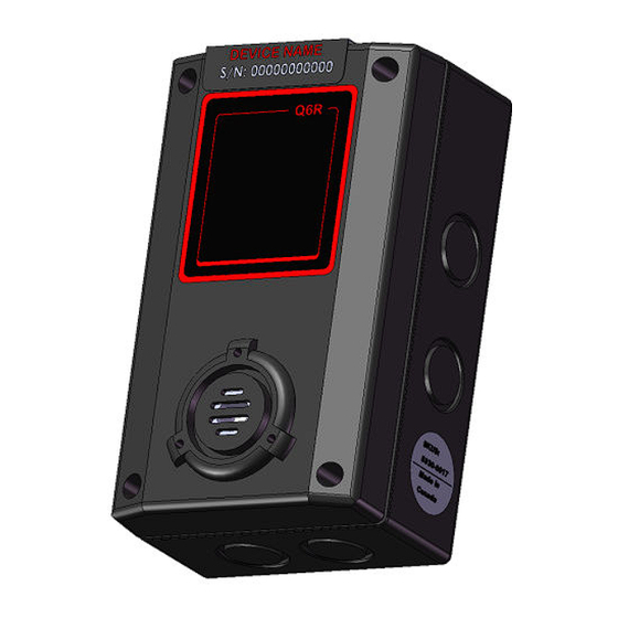
- Page 1 Dual-Sensor Gas Monitor INSTALLATION OPERATION AND MAINTENANCE MANUAL AUTOMATION COMPONENTS, INC. 2305 PLEASANT VIEW ROAD | MIDDLETON, WI 53562 PHONE: (888) 967-5224 FAX: (608) 831-7407 Web: workaci.com...
-
Page 2: Table Of Contents
Q6 Operation And Maintenance Manual READ BEFORE OPERATING ........................2 SPECIFICATIONS ..........................2 ................... 2 LECTRICAL ECHANICAL PECIFICATIONS ......................... 4 ENSOR PECIFICATIONS INSTALLATION ..........................6 ..................... 6 NCLOSURES HYSICAL IMENSIONS ............................... 6 OCATION ............................. 7 ERMINALS 2.3.1 Wire and Cable ..........................8 2.3.2 Power Requirements ........................ -
Page 3: Read Before Operating
The Q6 is a state-of-the-art dual-sensor gas monitor that can operate as an independent, stand- alone system or as part of an integrated system. The Q6 connects with digital interface to ACI Q-Controller or M-Controller, or any PLC/DCS through Modbus RTU protocol. Setup procedures are simplified with user friendly touchable buttons and LCD menus. - Page 4 55 dB at 10 feet, 2700 Hz Buzzer: Buzzer 1, 2, 3: Programmable tone Tone: chirp once / chirp twice / 50% duty cycle / constant ON RS-485 with ACI Controller Protocol Output Signal: • Available Controller: M-Controller, Q4 Controller and Q-Controller RS-485 with Modbus RTU protocol IP 66 &...
-
Page 5: Sensor Specifications
Q6 Operation And Maintenance Manual 1.2 Sensor Specifications Operating Code Symbol Span Density Temperature Lighter -10°C to +50°C Methane 0 - 100%LEL Propane C3H8 Heavier 0 - 100%LEL -10°C to +50°C Hydrogen Lighter 0 - 100%LEL -10°C to +50°C Combustible 0 - 100%LEL -10°C to +50°C Slightly... - Page 6 Q6 Operation And Maintenance Manual Heavier Phosphine 0 – 1ppm -20°C to +40°C Heavier Silane SiH4 0 – 50ppm -20°C to +40°C Heavier Germane GeH4 0 – 2ppm -20°C to +40°C Slightly 100 Diborane B2H6 0 – 2ppm -20°C to +40°C Lighter Slighter -20°C to +50°C...
-
Page 7: Installation
Q6 Operation And Maintenance Manual 2. Installation 2.1 Enclosures Physical Dimensions The enclosure is a NEMA 4 rated enclosure and can be wall mounted with 4 screws. To maintain the NEMA rating, it is important that the conduit opening is sealed upon installation. 2.2 Location The transmitter should be mounted where the gas to be measured is most likely to be present. -
Page 8: Terminals
Q6 Operation And Maintenance Manual 2.3 Terminals Q6M Terminals Q6R Terminals 86650-001-000 RB Feb 22, 2019... -
Page 9: Wire And Cable
AC source. Use extreme caution when sharing a common AC source. Sharing a common DC source is less problematic. • ACI Q-Controller uses half-wave rectifier only, M-Controller uses full-wave rectifier only, so the Q6 can work with both controllers •... -
Page 10: Q6 Works Alone
Q6 Operation And Maintenance Manual 2.3.3 Q6 works alone 86650-001-000 RB Feb 22, 2019... -
Page 11: Q6 Connection With Q-Controller
Q6 Operation And Maintenance Manual 2.3.4 Q6 Connection with Q-Controller 2.3.5 Q6 Connection with M-Controller 86650-001-000 RB Feb 22, 2019... -
Page 12: Rs-485 Terminator
Q6 Operation And Maintenance Manual 2.3.6 RS-485 Terminator Factory default setting is disabled terminator. The Q6M supplies this resistor on the main board, and it is chosen using a jumper at J4. • J4 1-2: Terminator Disabled / OFF (default) •... -
Page 13: Function And Configuration
Q6 Operation And Maintenance Manual 3. Function and Configuration 3.1 Indicators The indicators consist of five LED’s – two to indicate RS-485 digital communication, three to indicate the status of relays 1-3. 3.1.1 RS485-TX/RX When the Q6M is connected to a controller system via RS-485, the traffic of the communication can be monitored visually through the two RS-485 indicators. -
Page 14: Tool Function
3.2.4 Reset MENU Password If you forgot the main menu password, you can reset the menu password to default password “4321” by entering a correct active code. For the active code, contact ACI. 3.2.5 Exit Tool Mode Press key [F3] to return to monitoring mode. -
Page 15: Main Menu Tree
Q6 Operation And Maintenance Manual 3.3 Main Menu Tree The main menu is password protected. Once the password is accepted, you are allowed into the main menu tree. Factory default password is 4321. Note: While in the menu tree, all normal monitoring operations stop. The alarm status does not change. -
Page 16: Menu "1_System Setup
Q6R address would be address + 1 Note: In Modbus protocol, the address 0 is for broadcast. Baud rate: Define baud rate for RS-485 communication with ACI controllers OptoMux protocol or other SCDA system with Modbus protocol. Q6 default baud rate is 4800 bps Scroll Rate: In normal operation, the sensor and relay status information scrolls automatically. - Page 17 Q6 Operation And Maintenance Manual Display • Display Instant: displays instantaneous gas concentration Mode: • Display Average: o Displays STEL (15min average reading) o Displays TWA (8 hour average reading) o Displays daily peak • Display Alarm: displays alarm 1-8 status •...
- Page 18 Q6 Operation And Maintenance Manual Adjust real time clock. ADJ Clock: Adjust the LCD contrast. Valid values are between 10 (light) and 50 (dark). Contrast: Default is 21. Q6 Sensors: If the smart sensor in Q6M unit is not installed, it can be disabled here, so the Q6M will not detect the smart sensor board and will not report any fault on the sensor offline If the smart sensor in Q6R is not installed, it can be disabled too.
-
Page 19: Menu "2_Zero Cal
Q6 Operation And Maintenance Manual 3.5 Menu “2_ZERO CAL” First to select which sensor is going to be calibrated, Q6M or Q6R? The subsequent zero calibration will be performed on that sensor. The calibration is using a two-point calibration process. First, use a “Zero Gas”, then use a “CAL Gas”... -
Page 20: Menu "3_Span Cal
Q6 Operation And Maintenance Manual 3.6 Menu “3_SPAN CAL” First to select which sensor is going to be calibrated, Q6M or Q6R? The subsequent span calibration will be performed on that sensor. • “3_ SPAN CAL” 3_ SPAN CAL • Press key [F3] and the device will ask for the CAL GAS, input the concentration of the calibration gas. -
Page 21: Menu "4_Out Test
Q6 Operation And Maintenance Manual 3.7 Menu “4_OUT TEST” During system installation and testing, it may be necessary to force relays and buzzers on and off. The Relay Testing feature allows the user to force the actuation of each relay. This function forces an Actuate vs. -
Page 22: Menu "5_View Setting
Q6 Operation And Maintenance Manual 3.8 Menu “5_VIEW SETTING” This function is to verify the settings for the alarms, relays, buzzers and analog outputs. Note: The View of A-Out Setup is not available for Q6. INPUT: INSTANT 1. VIEW VIEW : 25PPM ALARM SETUP ALARM 2... -
Page 23: Menu "6_Alarm Setup
Q6 Operation And Maintenance Manual 3.9 Menu “6_ALARM SETUP” First to select which sensor’s alarm is going to be set, Q6M or Q6R? The subsequent alarm settings will be performed on that sensor. The Q6M supports alarm 1 to alarm 8 on its sensor. The Q6R supports alarm 1 to alarm 8 on its sensor too. -
Page 24: Menu "7_Relay Style
Q6 Operation And Maintenance Manual 3.10 Menu “7_RELAY STYLE” Each relay may be individually set to be enabled or disabled. If it’s Enabled: disabled, the relay will always de-actuate no matter what the current gas concentration. Default is Enabled. Each relay may be individually set to be normally energized or normally Normally de-energized. -
Page 25: Menu "8_Buzzer Style
Any concentration between 0ppm and 9999ppm can be simulated. 3.14 Menu “C_SITE SERVICE” and “D_FACTROY SET” Factory service staff access only. The customer has no need to operate it. 4. MODBUS Protocol Supported By Q6 For Modbus protocol, please contact ACI. 86650-001-000 RB Feb 22, 2019... -
Page 26: Maintenance
Important: Calibrate the monitor whenever a component is replaced. But if you replace a smart sensor assembly with a sensor onboard from ACI, you don’t need to recalibrate the monitor, as all the calibration information has been stored in the smart sensor board in the factory process. -
Page 27: Accessories
Q-View & USB-RS485 Converter Kit SKU#: 85930-004-000 Q-View is Windows based software running on a PC to used configure Q6 sensors through an RS-485 network. It supports the ACI controller protocol (OptoMux) and ModBus protocol. 86650-001-000 RB Feb 22, 2019... -
Page 28: Troubleshooting
Q6 Operation And Maintenance Manual 6. Troubleshooting This troubleshooting guide is intended as an aid in identifying the cause of unexpected behavior and determining whether the behavior is due to normal operation or an internal or external problem. SYMPTOMS PROBABLE CAUSE SUGGESTED SOLUTION RS-485 •... - Page 29 ACI shall not be responsible for any liability arising from auxiliary interfaced equipment nor any damage resulting from the installation or operation of this equipment. ACI’s total liability is contained as above with no other liability expressed or implied, as the purchaser is entirely responsible for installation and maintenance of systems.
Need help?
Do you have a question about the Q6 Series and is the answer not in the manual?
Questions and answers