Table of Contents
Advertisement
CONNECT Industrial Smart Hub
Model
CONNECT-X
CONNECT-W
Download the latest version of this document at
http://www.desouttertools.com/info/6159924300_EN
Read all safety warnings and instructions
Failure to follow the safety warnings and instructions may result in
electric shock, fire and/or serious injury.
Save all warnings and instructions for future reference
Product Instructions
Part number
6159327220
6159327230
WARNING
Printed Matter No. 6159924300_EN
Issue No.
05
Date
03/2020
Page
1 / 84
Advertisement
Table of Contents

Summary of Contents for Desoutter CONNECT Series
- Page 1 Printed Matter No. 6159924300_EN Issue No. Date 03/2020 Page 1 / 84 CONNECT Industrial Smart Hub Product Instructions Model Part number CONNECT-X 6159327220 CONNECT-W 6159327230 Download the latest version of this document at http://www.desouttertools.com/info/6159924300_EN WARNING Read all safety warnings and instructions Failure to follow the safety warnings and instructions may result in electric shock, fire and/or serious injury.
-
Page 2: Table Of Contents
Table of Contents Product Information .......................... 4 General Information......................... 4 Warranty.......................... 4 Website .......................... 4 Information about spare parts .................... 4 Dimensioning ........................ 4 CAD files .......................... 5 Overview ............................ 6 General overview ......................... 6 Product description ...................... 7 Technical data........................ 8 Accessories.......................... 9 Network and WI-FI settings.................... 11 Installation............................ 14 Installation Requirements...................... 14 Checking the line voltage .................... 14 Required distances for installation .................. 14 Minimum compatible versions.................... 14 Installation Instructions........................ 14... - Page 3 Troubleshooting .......................... 68 What if the tightening unit is not active.................. 68 Tool connection lost ........................ 69 What information to send to Desoutter support................ 69 How to use an existing RIM into another CONNECT.............. 70 How to monitor your system by using the user infos.............. 70 List of user infos .......................... 71...
-
Page 4: Product Information
• The product warranty relies on the correct use, maintenance, and repair of the tool and its component parts. • Damage to parts that occurs as a result of inadequate maintenance or performed by parties other than Desoutter or their Certified Service Partners during the warranty period is not covered by the warranty. -
Page 5: Cad Files
Product Information 8.94 3.54 8.74 8.28 8.46 15.35 CONNECT-X 8.94 3.54 8.74 8.28 8.46 CAD files For information about the dimensions of a product, see the Dimensional drawings archive: 03/2020 5 / 84... -
Page 6: Overview
Overview General overview CONNECT is the Desoutter premium platform for tightening solutions. • CONNECT-W has an embedded WI-FI access point and allows to manage up to 10 cordless tools with internal access point and 20 with an external access point. -
Page 7: Product Description
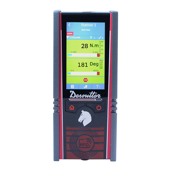
Product Information Product description Front panel Home button LEDs Blue Green Power management button Touchscreen RFID antenna Start screen Upon initial powering on, the following screen is displayed. CONNECT name is on the top. Click the arrow at the bottom. 03/2020 7 / 84... -
Page 8: Technical Data
Product Information Main buttons and icons Tap this icon to access the tightening results and curves. Tap this icon to configure: • System • Tightening units • Tools • Psets • Assembly Processes • Feature management Tap this icon to access the following actions. •... -
Page 9: Accessories
Product Information Weight Model CONNECT-X 4.63 CONNECT-W 4.63 Storage and use conditions Storage temperature -20 to +70 °C (-4 to +158 F) Operating temperature 0 to 45 °C (32 to 113 F) Storage humidity 0-95 % RH (non-condensing) Operating humidity 0-90 % RH (non-condensing) Altitude up to 2000 m (6562 feet) - Page 10 Product Information Length Length Area Part number 8.20 6159177400 China 8.20 6159177420 CONNECT can be equipped with an optional accessory to prevent users from removing the RIM. RIM cover protection 6152111240 CONNECT can be equipped with an optional accessory which allows to tilt the hub every 7.5° (min. -15°/max. +15°).
-
Page 11: Network And Wi-Fi Settings
Desoutter default parameter IP address (Ethernet 1) 192.168.5.212 Subnet mask 255.255.255.0 Gateway 127.0.0.1 Default Access Point Ethernet configuration For external Desoutter Access Point: Item Desoutter default parameter Other possible values IP address 192.168.5.201 Refer to local settings Subnet mask 255.255.255.0... - Page 12 Product Information Item Desoutter default parameter Other possible values Data rate 54 Mbit 1 Mbit 2 Mbit 5.5 Mbit 6 Mbit 9 Mbit 11 Mbit 12 Mbit 18 Mbit 24 Mbit 36 Mbit 48 Mbit 65 Mbit (MCS7) 6.5 Mbit (MCS0) 13 Mbit (MCS1) 19.5 Mbit (MCS2)
- Page 13 Product Information Radio ETSI TELEC Channel band North America Europe Japan Worldwide U-NII-2 U-NII-2 Ext U-NII-3 03/2020 13 / 84...
-
Page 14: Installation
Installation Installation Installation Requirements Checking the line voltage Before connecting CONNECT to the main supply, check that the line voltage is appropriate. Line voltage (V) 100-120 / 200-240 V~ The symbol ~ means "alternating current". Required distances for installation The maximum distance advised between CONNECT or the external WI-FI access point and the farthest tool is 30 meters (98.42 ft) without obstacles such as metallic objects. - Page 15 Installation Inside panel ON/OFF switch Plug for power cord 24 V DC connector RS232 port eBUS port Ethernet ports 1 and 2 Ethernet ports 3 and 4 Port 4 is a PoE Ethernet port. "PoE" stands for "Power over Ethernet" 2 USB ports Fieldbus module slot Installing the wall mounting kit...
- Page 16 Installation Place CONNECT on the kit as follows. Position CONNECT against the wall-mounting kit so that the rear slots fit into the lifting lugs of the kit. Let CONNECT drop. It will be locked into place with a distinct click. Installing the advanced wall mounting Mount the accessory on a DIN rail or wall.
- Page 17 Installation 2.17 2.76 Pull the knob out to tilt the accessory (-15°/+15°) to tighten the screws more easily. Place CONNECT on the wall mounting kit as shown previously. 03/2020 17 / 84...
- Page 18 Installation Installing the IP54 kit The RIM cover protection has to be installed over the IP54 kit. Installing the RIM cover protection Routing the cables 18 / 84 03/2020...
- Page 19 Installation Open the side door by pressing the button located on the door. Push the door against CONNECT. It will remain in place thanks to the magnet. Plug the cables and pass them through the grommet. Removing CONNECT from the wall mounting kit Power OFF the switch of the inside pane.
- Page 20 Installation Connecting to 24 V DC input power supply Plug the cable connector to (1). Refer to the following pin layout (2) to connect the cable to an external 24 V DC input. The maximum current for each pin is 1.5 A. + 24 V DC + 24 V DC RS422 RX +...
- Page 21 Open the side door. Push the ON/OFF switch to I. This will turn the system on. Keep pressing the Power Management button on the front panel. LEDs are blinking and the Desoutter logo ap- pears. The start screen is displayed and the green LEDs remain steady.
-
Page 22: How To Set Up Networks
Plug an Ethernet cable into any available Ethernet port of the inside panel and connect it to the WI-FI access point. How to set up networks Overview about networks Desoutter systems, such as CONNECT-X, CONNECT-W, CVI3 controller, can be connected to the factory Ethernet networks. Desoutter Ethernet 1 is typically the wired network dedicated to production lines. - Page 23 Installation How to select the network configuration Be sure that each IP address is unique and valid. The network configuration depends on the model of CONNECT you have. CONNECT-X: tools communicate with the WI-FI access point of the production line. CONNECT-W: tools communicate with its embedded WI-FI access point.
- Page 24 Installation Tap this icon. Give a SSID for CONNECT. Type a valid IP address for the WI-FI access point of CONNECT. Tap this icon. Fill in the wireless parameters. Tap this icon to validate. Blue LEDs will be blinking during the change of configuration. They will then remain steady to indicate that the embedded WI-FI access point is working properly.
- Page 25 Installation Go to the start screen and tap this icon. Tap System > Peripherals / Networks. Tap this icon. Give a name to each network. Type a valid IP address for each network and for each CONNECT. Tap this icon to validate. Blue LEDs will be blinking during the change of configuration.
- Page 26 Installation Tap System > Peripherals / Networks. Tap this icon. Give a name to each network. Type a valid IP address for each network and for each CONNECT. For CONNECT-W, tap this icon to display the screens for the WI-FI access point.. Untick WI-FI access point activated.
-
Page 27: Pairing Tools Via Rfid
Installation Tap this icon. Go to the box Linked to and select Ethernet 1. Enter the parameters of the embedded access point in page 1 and 2. Tap this icon to validate. Blue LEDs will be blinking during the change of configuration. They will then remain steady to indicate that the embedded WI-FI access point is working properly. -
Page 28: Pairing Tools Via Edock
Installation EPBC BLRTC Pairing tools via eDOCK Plug a battery pack to the tool. Connect eDOCK to the tool and to the USB port of CONNECT. Respect the connection order. EABS EABC 28 / 84 03/2020... - Page 29 Installation EPBC BLRTC ELC-A-W Press the trigger while inserting the battery pack. The reporting LED will blink. 03/2020 29 / 84...
-
Page 30: Initial Configuration
Installation ELC-P-W Press the trigger while inserting the battery pack. The reporting LED will blink. Initial Configuration Name, torque unit, speed unit, keypad beep, sleep mode Go to the start screen and tap this icon. Tap System > User interface > Display. Customize the name of CONNECT. -
Page 31: Setting Date, Time And Synchronization
Installation Tap System > User interface > Language. The following languages are available: English Russian French Portuguese Spanish Dutch German Portuguese (Brazil) Swedish Korean Italian Farsi Japanese Czech Chinese Turkish Polish Select your language. Tap this icon to validate. Setting date, time and synchronization This function is used to synchronize the system date and time to ensure that the tightening results are stored with the correct date and time. - Page 32 Installation You can now control the display from your PC. For example: Apple Install the free application Mocha VNC Lite on your device. Set up a Wi-Fi access point connected to the tightening product. Set up the SSID / Password. Set up the IP address of the access point and connect it to the tightening product.
-
Page 33: Operation
Operation Operation Configuration Instructions How to create a tightening unit Create one tightening unit per tool. Before starting, check that the RIM contains enough UVs for the planned configuration. If not, go to the chapter Rebalancing UV to the RIM [Page 57] Launch CVI CONFIG. -
Page 34: How To Set Up A Simple Pset
Operation The WI-FI icon on the top left is activated. The tool is associated to this tightening unit. Go to CVI CONFIG. Click this icon to update CVI CONFIG. How to set up a simple Pset Setting the running mode to Pset Go to the start screen and tap this icon. - Page 35 Operation Select the tightening unit in the list. Tap this icon to edit. Go to the box Pset source and select Front panel. Other possibilities are as follows: • I/O • CVILOGIX • Open Protocol • Fieldbus • Customized protocol •...
- Page 36 Operation Tap this icon. Keep the tool connected. Tick Simple mode. Tap this icon. Tap the box Target torque. Tap this icon to clean the box. Type your target torque. 36 / 84 03/2020...
- Page 37 Operation Tap this icon to validate. Tap this icon. Tap this icon to validate. Tap this button on the front panel to display the start screen. 03/2020 37 / 84...
- Page 38 Operation Swipe the tile to the right to access the Pset. Tap this icon. Select Pset 1 in the list. Tap this icon to validate. 38 / 84 03/2020...
- Page 39 Operation Executing the Pset Press the tool trigger to run Pset 1. Swipe the tile to display the results. Tap the title of the tile. The simple view is displayed by default. 03/2020 39 / 84...
-
Page 40: How To Set Up A Simple Assembly Process
Operation Tap this icon to see the other possible views The view you will select now will be the one by default for the next tightenings. Detailed view Curves view How to set up a simple Assembly Process Setting the running mode to Assembly Process Go to the start screen and tap this icon. - Page 41 Operation Tap Tightening unit. Select the tightening unit in the list. Tap this icon to edit. Go to the box Running mode and select Assembly Process. Tap this icon to validate. Creating an Assembly Process Go to the start screen and tap this icon. Tap Assembly Process.
- Page 42 Operation • Tool display Select the Pset to execute. Enter the batch size i.e. the number of times the Pset will be executed: 1-99 or unlimited. Example: Tap this icon to validate. Executing the Assembly Process Tap this button on the front panel to display the start screen. Swipe the tile.
- Page 43 Operation The tool is ready to execute Assembly Process 1 with Pset 1. Apply the tool to the joint to tighten. Press the tool trigger to execute the Assembly Process. Go to CONNECT. Click Tightening 51 to have access to the display selection. Click this icon to access to the different types of views.
-
Page 44: Sending Results To Cvinet Web Database
Operation When the Assembly Process is done, the tool is locked again waiting for the next one. Click this icon to see the reason why the tool is locked. Sending results to CVINET WEB database Go to the start screen and tap this icon. Tap System >... -
Page 45: Operating Instructions
Operation The system is regularly sending results to CVINet. The purpose is to provide a full traceability even when the network connection is unstable. 1. The system is able to keep a defined number of results previously generated by each tightening unit (typi- cally 10,000). -
Page 46: How To Perform Actions On The On-Going Assembly Process
Operation Tap this icon to search for a Pset not displayed in the list. Tap this icon to type directly the Pset number in the digital keyboard. Tap this icon to validate. How to perform actions on the on-going Assembly Process At any time during the process, you can do the following actions. - Page 47 Operation Searching for a specific result Go to the start screen and tap this icon. Select a result and tap this icon. The following information is displayed: • stop source • tool serial number • Pset number • torque value •...
- Page 48 Operation Tick this icon. Tap the down arrow to see criteria. Select the following filters. General status • All • OK • NOK • Loosening • Angle value Stop type • All • No stop • Overcurrent • Trigger release •...
-
Page 49: How To Get And Read Curves
Operation • Yield point reached • Torque / Angle / Time stop • Remove fastener torque limit • Hardware failure • Unknown Tap this icon to validate. How to get and read curves How to get curves displayed Go to the start screen and tap this icon. Tap Tightening unit. - Page 50 Operation Tick Enable curves. It may happen that there is no curve because the results are not representative. Tap this icon to validate. How to read curves Go to the start screen and tap this icon. Tap the torque value of result 20. The line turns grey. Tap this icon.
- Page 51 Operation Tap the icon on the left to go to the last value. Tap the icon on the right to go to the first value. Tap this area to get more information about the result. Tick the values you want to have by default each time a curve is displayed. Click Curves selection to validate your selection.
-
Page 52: Shortcuts And Tips
Operation How to zoom in a curve Slide from the top left to the bottom right to zoom in a particular area. Tap anywhere to return to the initial screen. Shortcuts and tips How to quickly pair a tool When the tool is not connected, i.e. the WI-FI icon is not active, it is possible to quickly pair another tool. See below that the tool of Tightening Unit -51 is not active. - Page 53 Operation Execute the pairing via eDOCK or RFID as described previously. How to quickly get the full screen view of a tightening unit Click the name of the tightening unit to access to the last view selected. Click this icon to access to the main menu. Click this icon to access to the different types of views.
- Page 54 Operation Tap this icon to get the list of Psets available for this tightening unit. Select a Pset. How to use shortcuts of tiles and pop-up messages The way to handle shortcuts of tiles is the same, regardless the color. Example: Tap the body of the tile.
-
Page 55: Service
Service Service About features How to read the status of features Status Description Not active The feature is configured in the Tightening unit settings but NOT activated in the pane "Current configuration". Active The feature is configured in the Tightening unit settings AND active in the pane "Cur- rent configuration". -
Page 56: How To Save And Back Up Data
Service See the feature Up to 50 Psets is Active. Pset 11 is active in the tree view. Click this icon to update the product. How to save and back up data Saving results on a USB key Make sure not to tighten during the backup of results. Plug a USB key to the bottom panel. -
Page 57: How To Save Connect Data In Real-Time
Service How to save CONNECT data in real-time Go to the start screen and tap this icon. Tap RIM > Backup / Restore. Select Auto backup to have each modification saved in real-time. The RIM acts as a mirror of CONNECT. Press Start. - Page 58 Service Plug your eWallet to the USB port of the front panel. You can replace the name RIM or the serial number by a customized description. Tap the serial number or the name RIM and enter the new description. See the number of UV available in this eWallet. Tap both tiles to select them.
- Page 59 Service Tap the box "0" of the RIM or slide the cursor to fill in the box with UV. Press the button "Start". Reminder 86 UV are needed to activate one tightening unit. The white tick indicates the transfer is done. Tap this icon to quit.
-
Page 60: How To Manage Uv Counters
Service How to manage UV counters Launch CVI CONFIG. Check that CONNECT is connected to the computer. Go to the tree view and create the product CONNECT. Click Feature management. Go to the box UV counters. Note that the serial number and the firmware version of the RIM plugged to CONNECT are displayed on the right side. - Page 61 Service Click this icon to update the product. Note that 97 UVs have been assigned and that 91 UVs remain available. Assigned UVs Activate Tightening unit - 52. Click this icon to update the product. Note that 183 UVs have been assigned and that 5 UVs remain available. Required UVs Activate Tightening unit - 53.
- Page 62 Service Note that 81 UVs are required to fit the configuration. Click Check UV amount. The red cross indicated that UVs are missing. It is not possible to transfer the configuration to CONNECT. Fill in the RIM of CONNECT with the required UVs. Click this icon to update CVI CONFIG.
-
Page 63: Tool Maintenance
Service The number of UVs is sufficient to accept the configuration. The number of UVs is not sufficient to accept the configura- tion. Tool maintenance Getting information about tools The following information is available in read-only mode. • identification • characteristics •... -
Page 64: Monitoring The Tool Calibration Status
• Barcode reader • Front light • I/O accessory Changing the tool configuration is performed by Desoutter technicians only. It is mandatory to calibrate the tools after they have been modified. Contact your Desoutter representative to get more information and support. -
Page 65: Monitoring The Tool Counters
When the date of the next calibration is reached, a pop-up appears on the tool display asking to perform the cali- bration. Calibration is performed by Desoutter technicians only. Contact your Desoutter representative to get more information and support. Monitoring the tool counters Go to the start screen and tap this icon. -
Page 66: Maintenance Instructions
Service Maintenance instructions Cleaning If needed, clean the external panels by using a dry cloth. Maintenance program Please consult us on the Tool Care program that includes production support and maintenance solutions. Spare parts Exploded views and spare parts lists are available at https://www.desouttertools.com/resource-centre. The use of spare parts other than those originally supplied by the manufacturer may result in a drop in performance or in increased maintenance and level of vibration and in the full cancellation of the manufacturer’s liability. -
Page 67: Upgrading Firmware
Service Tap this icon to quit. Upgrading firmware Contact your Desoutter representative to get the last firmware version. Copy the files to the root of a USB key. Plug the USB key into the front panel. Go to the start screen and tap this icon. -
Page 68: Troubleshooting
Troubleshooting Troubleshooting What if the tightening unit is not active See above that Tightening unit - 53 is not active. The tool can be paired but it will not run. Go to the menu Feature management and rebalance the required UVs to the RIM. Plug an Ethernet cable to any Ethernet port of CONNECT and to a computer. -
Page 69: Tool Connection Lost
The tool is not connected anymore. Click this icon to see the reason why the tool is locked. What information to send to Desoutter support If you think that the product is not functioning properly or if you encounter unexpected behaviours, do not hesitate to contact your Desoutter representative for support. -
Page 70: How To Use An Existing Rim Into Another Connect
Remove the USB key and plug it to your computer. Go to the root of the USB key and zip all folders into one. Send the zip file to your Desoutter representative. How to use an existing RIM into another CONNECT Before unplugging the RIM, go to Maintenance >... -
Page 71: List Of User Infos
Troubleshooting Go to the start screen and tap this icon. Tap System > User info log. The most recent event is on the top. Select a log and tap this icon to get the details. Use the up and down arrows to scroll the list. Tick the box Filter to display the filtering options. - Page 72 2- Verify communication ports and IP addresses. I100 Cable ID invalid parameter 1- Invalid tool cable parameter. 2- Check that the tool cable is Desoutter certified. 3- Contact your Desoutter representative for support. I101 Cable ID not detected 1- Tool cable communication error.
- Page 73 Pset invalid parameters 1 - Software internal error. 2 - Pset is corrupted. Try to transfer it again to the sys- tem. 3 - If the error persists, contact your Desoutter repre- sentative for support. I215 Current calibration error 1- Current calibration failed.
- Page 74 Procedure I254 Drive communication error 1- Error detected in drive communication. 2- Restart the system. 3- If the problem occurs again, contact your Desoutter representative for support. I259 Reset input active 1- "Reset" input is active. 2- The tightening unit will unlock when input switches to "Inactive".
- Page 75 I899 Downgrade not allowed 1- Software downgrade is not allowed for this version. 2- Check the software image version on your USB key. 3- If the problem occurs again, contact your Desoutter representative for support. I900 Software update failed 1- Software upgrade failed.
- Page 76 Additional transducer offset failure 1- Offset value from additional torque sensor is outside bounds. 2- Restart the tool with no mechanical constraints. 3- If the problem occurs again, contact your Desoutter representative for support. I924 Tool calibration required 1- Perform a calibration of the tool.
- Page 77 2- The damaged tool needs maintenance. E013 Bad tool ground 1- Phase-phase or phase to ground short-circuit. 2- Disconnect the tool. Contact your Desoutter repre- sentative for support. E014 Torque power default 1- The torque sensor is not correctly supplied.
- Page 78 2- Check the Phoenix connector. E213 Drive connection lost 1- Connection with the drive has been lost. 2- Reboot the system. 3- If the issue remains, contact your Desoutter repre- sentative for support. E217 Drive disabled 1- Drive disabled by external source.
- Page 79 Missing UV 1- The UV amount of the configuration is greater than the number of UVs available in the RIM. 2- Allocate UVs to this RIM. 3- Contact your Desoutter representative for more in- formation. E705 Missing demo UV 1- The demo UV amount of the configuration is greater than the number of demo UVs available in the RIM.
- Page 80 2- The Pset uses an additional transducer not installed on the tool. E927 Corrupted RIM information 1- It is not possible to use this RIM. 2- Contact your Desoutter representative for support. E928 Tracking System communication failed 1- Tracking System communication failed. E935 1 Working Space: demo expired 1 - The demo period for this feature was 90 days.
-
Page 81: List Of User Infos Related To The Tools
1- The tool tightening counter has been reached. I038 Tool logs 1- Unexpected tool software exception. 2- Log file has been generated by the tool. 3- Contact your Desoutter representative for support. I046 Abnormal battery current 1- Abnormal battery current consumption. Check the Pset settings. - Page 82 2- Check the tool cable is not damaged. W212 Result not stored 1- It is not possible to store the tightening result in the system. 2- Contact your Desoutter representative for support. W216 Current high 1- Maximum current exceeded. 2- Contact your Desoutter representative for support.
- Page 83 2- Replace the battery pack or your configuration. E223 Drive init error 1- Software failure. 2- Restart the system. 3- If the problem occurs again, contact your Desoutter representative for support. E227 Motor stalled 1- Motor stalled (could be missing phase, wrong motor tune or power electronics failure) 2- Try once again.
- Page 84 Original instructions Founded in 1914 and headquartered in France, Desoutter Industrial Tools is a global leader in electric and pneumatic assembly tools serving a wide range of assembly and manufacturing operations, including Aerospace, Automotive, Light and Heavy Vehicles, Off-Road, General Industry.
Need help?
Do you have a question about the CONNECT Series and is the answer not in the manual?
Questions and answers