Advertisement
Table of Contents
- 1 Table of Contents
- 2 Safety
- 3 General Description
- 4 Main Parameter
- 5 Structure of Welder
- 6 Installation
- 7 Welding Settings Quick Reference Chart
- 8 Range of Welding Current and Voltage in CO2 Welding
- 9 Welding Parameters Table
- 10 Caution
- 11 Maintenance
- 12 Daily Checking
- 13 Connection Diagram of the Machine
- 14 Explosion Drawing
- 15 IGBT Equipment Warranty
- Download this manual
Advertisement
Table of Contents

Related Manuals for Blue Demon IGBT Series


Summary of Contents for Blue Demon IGBT Series
- Page 1 OWNER'S MANUAL THE IGBT SERIES OF MIG/MAG BLUE DEMON BLUEARC 140MSI...
-
Page 2: Table Of Contents
CONTENTS - 1.Safety……………………..………………..…………………………….…..……..……………………………………………………. - 2.General Description……...………..……...…………………….………...………..……………………………………….. -3.Main Parameter…….……...…...……..………………………………….…..……….…………………………………… - 4.Structure of welder…….……...…...………………………..…………….…..……….…………………………………… - 5.Installation ……………………………………………………………………………………………………………………………..… - 6.Welding settings quick reference chart………………………………………………………………………………………. - 7.Range of welding current and voltage in CO2 welding...……….…………………………………………………… - 8.Welding parameters table..…....……………………….………..…………………………………………… 18 - 9.Caution……….....…………………………………………...………………..…........- 10. Maintenance….………………………………………….……………….….……..….…………………………………………… - 11. - Page 3 This welding machine for industrial and professional use is in conformity with IEC974 International Safety Standard. We hereby state that we provide one year of warranty for this welding machine since the date of purchase. See full warranty disclaimer on last page of user manual. Please read and understand this instruction manual carefully before the installation and operation of this machine.
-
Page 4: Safety
1.SAFETY Welding and cutting is dangerous to the operator, people in or near the working area, and the surroundings if the machine is not correctly operated. Therefore, the performance of welding/cutting must only be under the strict and comprehensive observance of all relevant safety regulations. Please read and understand this instruction manual carefully before installation and operation. -
Page 5: General Description
2.GENERAL DESCRIPTION This welding machine is composed of an inverter MIG welder power supply with invariable voltage output external characteristics manufactured with advanced IGBT inverter technology designed by the manufacturer. With high-power component IGBT, the inverter converts the DC voltage, which is rectified from input 50Hz/60Hz AC voltage, to high frequency 20KHz AC voltage;... - Page 6 Block Diagram INPUT CONTROL...
-
Page 7: Main Parameter
3. MAIN PARAMETER Main Parameter MODEL BLUEARC-140MSI Power supply 120±10% voltage Rated input capacity Frequency(inverter) Rated input current 45\24.6 Output current 50-140 10-120 range Function 30% 140A 30% 120A Duty cycle (40℃ 60% 108A 60% 92A 10min) 100% 76A 100%65A No load voltage Efficiency Power factor... -
Page 8: Structure Of Welder
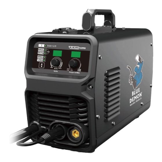
Structure of welder 1. Current adjustment 2. Voltage adjustment 3. Over temperature protection LED 4. Welding mode switch 5. Integrated MIG torch 6. Positive (+) Welding Output Terminal 7. Negative (-) Welding Output Terminal 8. Power switch 9. Power cable 10. - Page 9 15. Electrode holder 16. Alligator clip (ground clamp) 17. Nozzle 18. Contact Tip 19. Tip Adapter 20. Trigger 21. Handle...
-
Page 10: Installation
5.INSTALLTION 5.1. MIG Welding Set Up & Operation 5.1.1 Fitting the spool 5.1.1.1 open the cover door for the wire feed compartment. Remove the wire spool retainer(14) by threading off counter- clockwise. 5.1.1.2 fit either a 4in or 8in diameter wire spool to the spool holder, ensuring the end of the wires exits towards the wire feeder from the bottom of the spool. - Page 11 Connection of Shield Gas Connect inert gas hoes to gas inlet (10) with standard hose fitting and tighten securely. If using a hose without a fitting, secure with hose clamp. The supply of your inert shielding gas should include the gas tank (aka bottle), regulator, and gas hose.
- Page 12 5.1.5 Controls for MIG welding 1 Current adjustment 2 Voltage adjustment 3 Welding mode switch 4 VRD = Voltage Reduction Device indicator light safety feature to reduce OCV for improper MMA connection to operator. 5 MMA – SMAW mode 6 SYN-synergize voltage and ampere automatically 7 MANUAL-manually adjust voltage and ampere in GMAW/FCAW mode 8 Temperature overload indicator light , after cooling down, machine can work again.
-
Page 13: Welding Settings Quick Reference Chart
6.Welding settings quick reference chart... - Page 14 Basic welding guide MIG (GMAW/FCAW) Basic Welding Technique Two different welding processes are covered in this section (GMAW and FCAW), with the intention providing the very basic concepts in using the MIG mode of welding, where a welding gun is hand held, and the electrode (welding wire) is fed into a weld puddle, and the arc is shielded by an inert welding grade shielding gas or inert welding grade shielding gas mixture.
- Page 15 The welding gun should be held at an angle to the weld joint. (See Secondary Adjustment Variables below) Hold the gun so that the welding seam is viewed at all times. Always wear the welding helmet with proper filter lenses and use the proper safety equipment.
- Page 16 Primary Adjustable Variables These control the process after preselected variables have been found. They control the penetration, bead width, bead height, arc stability, deposition rate and weld soundness. They are: Arc Voltage Welding current (wire feed speed) Travel speed Secondary Adjustable Variables These variables cause changes in primary adjustable variables which in turn cause the desired change in the bead formation.
- Page 17 For practicing MIG welding, secure some pieces of 16 or 18 gauge (0.06” 1.5mm or 0.08” 2.0mm) mild steel plate 6” x 6” (150 x 150mm). Use 0.030” (0.8mm) flux cored gasless wire or a solid wire with shielding gas Setting of the Power Source Power source and Wire-`feeder setting requires some practice by the operator, as the welding plant has two control settings that have to balance.
-
Page 18: Range Of Welding Current And Voltage In Co2 Welding
7.Range of welding current and voltage in CO welding Short circuit transition Granular transition Wireφ(in) Current(A) Voltage (V) Current(A) Voltage (V) 0.023 40~70 17~19 160~400 25~38 0.030 60~100 18~19 200~500 26~40 0.035 80~120 18~21 200~600 27~40 -The option of the welding speed The welding quality and productivity should be taken into consideration for the option of welding speed. -
Page 19: Welding Parameters Table
8.WELDING PARAMETERS TABLE The option of the welding current and welding voltage directly influences the welding stability, welding quality and productivity. In order to obtain the good welding quality, the welding current and welding voltage should be set optimally. Generally, the setting of weld condition should be according to the welding diameter and the melting form as well as the production requirement. - Page 20 Parameter for fillet welding in the vertical position (Please refer to the following figure.) Welding Plate Welding Welding speed Corn size Wire Gas volume thickness current voltage (cm/min (L/min) I (mm) φ(mm) (A) (V) t(mm) ) 2.5~3.0 70~100 18~19 50~60 10~15 2.5~3.0 1.0 ~ 1.2...
-
Page 21: Caution
9.CAUTION 1. Working environment ⑴ Welding should be carried out in a relatively dry environment with its humidity of 90% or less. ⑵ The temperature of the working environment should be within -10C to 40C. ⑶ Avoid welding in the open air unless sheltered from sunlight and rain, and never let rain or water infiltrate the machine. ⑷... -
Page 22: Maintenance
10.MAINTENANCE 1. Disconnect input plug or power before maintenance or repair on machine. 2. Be sure input ground wire is properly connect to a ground terminal. 3. Check whether the inner gas-electricity connection is well (esp. the plugs), and tighten the loose connection; if there is oxidization, remove it with sand paper and then re-connect. -
Page 23: Daily Checking
11.DAILY CHECKING To make best use of the machine, daily checking is very important. During the daily checking, please check in the order of torch, wire-feeding vehicle, all kinds of PCB, the gas hole, and so on. Remove the dust or replace some parts if necessary. To maintain the purity of the machine, please use original welding parts. - Page 24 11.2. Welding torch Part Check Remarks 1. Check if the nozzle is fixed firmly Possible gas leakage occurs due to the unfixed nozzle. and distortion of the tip exists. Nozzle 2. Check if there is spatter sticking on Spatter possibly leads to the damage of torch. Use anti- the nozzle.
- Page 25 11.3. Wire feeder Part Check Remarks Pressure 1. Check if the pressure-adjusting handle is The unfixed pressure-adjusting handle leads to adjusting fixed and adjusted to the desired position. the unstable welding output. handle 1. Check if there is dust or spatter inside the Remove the dust.
-
Page 26: Connection Diagram Of The Machine
12.CONNECTION DIAGRAM OF THE MACHINE... -
Page 27: Explosion Drawing
13.EXPLOSION DRAWING... -
Page 28: Igbt Equipment Warranty
Base plate Hinge Rectifier radiator Machine cover Main board IGBT radiator(up) MIG wire spool shaft IGBT radiator(down) Lock Fixed beam Side plate Fan support MIG wire feeder Clapboard Control board Rear panel Front panel Power switch Quick connector Wire buckle Front plastic panel Welding gas inlet 14.IGBT Equipment Warranty... - Page 29 Limited Warranty This warranty applies to the original purchaser and is subject to the terms and conditions listed below. This Limited Warranty is for new equipment sold after the above date, providing coverage for defects in material and workmanship at the time it is shipped from the factory. Limited to the warranty periods listed below, Welding Material Sales will repair or replace the item under warranty that fails due to defects in material and workmanship.
Need help?
Do you have a question about the IGBT Series and is the answer not in the manual?
Questions and answers