Advertisement
Quick Links
Advertisement

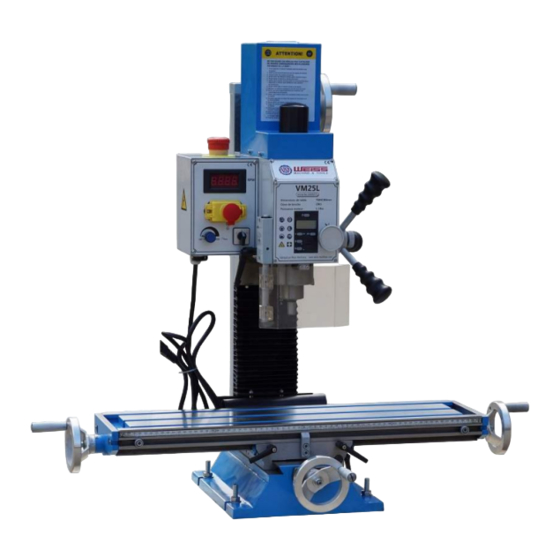
Summary of Contents for WEISS VM25L
- Page 1 VM25L...
- Page 2 - 1 -...
- Page 3 WARNING! Keep children and visitors away. All visitors Read and understand the entire instruction should be kept a safe distance from the work area manual before attempting set-up or operation of this mill/drill 14 Make the workshop child proof. Use padlocks, .
- Page 8 100-2250...
-
Page 9: Electrical Connections
ELECTRICAL CONNECTIONS WARNING! A qualified electrician must make all electrical connections! Failure to do so may cause serious injury! Before connecting the machine to the mains, make sure that the electrical values of the mains supply are the same as those for the machine’s electrical components. Use the wiring diagram (Fig. -
Page 11: Gibs Adjustment
GIBS ADJUSTMENT After a period of time, movement of the table over the ways will cause normal wear. Adjust the gibs to compensate for this wear. 1. The horizontal gib adjustment screw (A, Fig.16) is found to the rear right on table. The traverse gib adjustment screw (B, Fig.16) is found on the right side of saddle under the table. -
Page 12: Maintenance
Maintenance Keep the maintenance of the machine tool during the operation to guarantee the accuracy and service life of the machine. 1. In order to retain the machine’s precision and functionality, it is essential to treat it with care, keep it clean and grease and lubricate it regularly. - Page 13 VM25L MILL HEAD ASSEMBLY I 206-2 206-1 209-2 209-1 226-2 226-1 225-2 225-1 272 271 236 237 246-1 255-1...
- Page 14 VM25L MILL HEAD ASSEMBLY I Parts No. Description Specification Position Washer Bush 35 45 steel Spring 2.5x28x100 Snap Ring Φ 45 Bearing 6209 Gears 60/70T Raster Ring 16 Bore 206-1 206-2 Screw M3x8 Bearing 7007 Snap Ring Φ 15 Gears...
-
Page 15: Specification
VM25L MILL HEAD ASSEMBL Y II Parts No. Description Specification Base Locking Lever M8x20 Φ8x16.2 Brass Pin Mill Head Plate for Head Screw M4x8 Knob Set Screw M5x6 Spring Piece Dial Worm Shaft Spindl 246-1 Drawbar Ring M24x1 Bearing 32005... - Page 16 VM25L - MILLING & DRILLING MACHINE Column, Table, Base Assembly...
- Page 17 VM25L COLUMN,TABLE,BASE ASSEMBL Y I Parts No Description Specification Vertical Slide Screw M6x16 Washer Spring Washer Screw M8x25 Screw M12x40 Spring Washer T-Nut Bolt M10x60 Washer Spring Washer Block Brass Pin Φ5x10 Locking Lever M6x16 Gib Screw Angie lndication Label...
- Page 18 VM25L COLUMN,TABLE,BASE ASSEMBL Y II Parts No. Description Specification Bearing 6001 Shaft 4x12 Bearing Housing Bush Φ14 45 steel Gear Column Label A5x25 M6x16 Screw M6x14 Left Bracket Working Table Plug Right Bracket Handle M8x63 Handwheel Dial Bearing 51200 Screw...
- Page 19 VM25L - MILL ELECTRICAL BOX ASSEMBLY...
- Page 20 VM25L -...
Need help?
Do you have a question about the VM25L and is the answer not in the manual?
Questions and answers