
Summary of Contents for HamGadgets ID-O-Matic III
- Page 1 HamGadgets ID-O-Matic III Assembly, Setup and Use Guide 2014-01-17...
-
Page 2: Table Of Contents
Using Windows ............................. 4 Setting up PuTTY ........................... 5 Setting up HyperTerminal ........................7 Linux and Mac Software..........................8 Programming the ID-O-Matic III........................8 Timers and Time-Of-Day (TOD) Clock ....................11 Messages ............................. 13 Courtesy Beep ............................. 15 I/O Signal Polarity..........................16 Baud Rates ............................ -
Page 3: Introduction
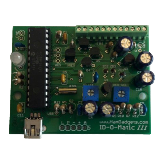
Introduction The HamGadgets ID-O-Matic III is a versatile ID timer and annunciator. It can be used as a relatively simple repeater controller with some advanced features such as “polite” ID, voice identification, courtesy tone, time-out timer and much more. While intended as a repeater controller, it’s also simple to set up for applications such as beacon transmitters, a “fox”... -
Page 4: Using Windows
Windows. Many PCs have only one serial port, named COM1. Some have more than one. Since the ID-O-Matic III appears as a virtual COM port, it can show up with different COM port numbers depending on which port it’s plugged into. You can use the Windows Device Manager to see what serial ports are available on your system. -
Page 5: Setting Up Putty
There is no special installation process; the program has a single executable file that can be run by itself. You can also use Windows HyperTerminal if you have it, or under Linux you can use Minicom. The example below uses PuTTY. 2014-01-17 ID-O-Matic III... - Page 6 You don’t need to change anything else. Type a name for this connection in the Now you can double-click the session name, “Saved Sessions” box – “ID-O-Matic” is a or select it and click Open. good choice. Click Save. 2014-01-17 ID-O-Matic III...
-
Page 7: Setting Up Hyperterminal
Modify the port settings for flow control = NONE. Since this is a USB connection, the bits per second setting does not matter. Click the “Call” icon (looks like a telephone). You should now be able to communicate with your ID-O-Matic. 2014-01-17 ID-O-Matic III... -
Page 8: Linux And Mac Software
4.) You should immediately see the response from the ID-O-Matic. Press ENTER to enter the setup menu, then refer to the following pages to set up your ID-O-Matic III. Remember that new settings are not automatically saved; make sure you save your changes before quitting! 5.) To exit the screen program, type Ctrl-a followed by K. - Page 9 I could make it. To change a timer value or to set the clock, type 1 and hit the ENTER key. To add or change a message, type 2 and hit the Enter key, and so on. 2014-01-17 ID-O-Matic III...
- Page 10 – so they will be lost if the board is reset or if power is turned off. If the timeout occurs before you’re finished making changes, you can re- enter the setup menu by pressing ENTER and pick up where you left off. 2014-01-17 ID-O-Matic III...
-
Page 11: Timers And Time-Of-Day (Tod) Clock
ID more “polite”. ID minimum: You may want the ID-O-Matic III to attempt to send the ID when there is no active user talking (COR idle). Setting the ID Minimum will cause the ID to be sent as soon after that time as possible, when COR is not active. - Page 12 – so for one second, enter “10”. Fan timer: If you are using the ID-O-Matic III to control a cooling fan, this is the amount of time in seconds that the fan will run after the PTT line drops. The fan timer is reset with each transmission.
-
Page 13: Messages
TOT (Time-Out Timer) message can be a maximum of 10 characters. Morse ID speed is self- explanatory, and the “ID on power-up” setting determines whether the ID message will be sent immediately when power is applied to the ID-O-Matic III. The Morse code ID tone (in Hz) can also be set here. - Page 14 The same is true of the ALT message; if you don’t set one up here, the ID message will be used. 3. You MUST have an ID message if you want to send anything – other than courtesy beeps, of course. 2014-01-17 ID-O-Matic III...
-
Page 15: Courtesy Beep
The beep delay is the amount of time after COR drops that the beep will be sent. This value is entered in tenths of a second, so for one second you would enter “10”. And lastly, the audio frequency of the courtesy beep can be set here, independent of the Morse code ID tone. 2014-01-17 ID-O-Matic III... -
Page 16: I/O Signal Polarity
Fan Control: You may wish to use your ID-O-Matic III to control a cooling fan or other device. The fan output can be selected to appear on any output signal that you don’t plan to use (the CW output is probably most common). -
Page 17: Baud Rates
GPS receiver used to set the real time clock. The default speed is 9600 BPS; if your GPS receiver requires a different setting you can enter it here. 2014-01-17 ID-O-Matic III... -
Page 18: Connecting To Your Equipment
Diodes will keep one power source from affecting the other, and the ID-O-Matic III will draw its power from whichever source has the highest voltage. This means you could, if you wish, attach a 12V DC power source to the terminal block, and put a mini USB plug on a small backup battery pack to keep the board powered in the event of a failure of the main power source. -
Page 19: Connections
Non-Repeater Use It’s possible (and quite common) to use your ID-O-Matic III to provide automatic Morse or voice ID for your HF, VHF or UHF transmitter or transceiver. Given the hundreds of different HF, VHF and UHF rigs out there, I cannot provide specific instructions for them. In general, though, it's a pretty simple proposition. - Page 20 On rigs with rear panel connections for TNCs and accessories, there may be PTT and audio signals available so you don't have to put it between the mic and the rig. It really depends on the rig; this is where you get to put your Amateur Radio experimental skills to work. 2014-01-17 ID-O-Matic III...
-
Page 21: Updating The Firmware
Updating the Firmware From time to time there may be new firmware released for the ID-O-Matic III. The processor has a “bootloader” built in that can accept new firmware from your PC. The process is relatively quick and painless. - Page 22 When it’s finished, you will see a message on the screen like this: When you close the terminal window, the ID-O-Matic III should automatically reset. If it does not, simply disconnect the power and connect power again. Check the firmware version; it should show that it’s running the new version you just loaded.
-
Page 23: Assembly Instructions
Assembly Instructions Assembling your ID-O-Matic III should be relatively easy if you have some prior kit building experience. There are no surface mount parts, and only a few of the components will require any special techniques. If you feel you may have trouble completing the assembly, or if this is your first attempt at kit building, it would be a good idea to enlist the help of a more experienced builder. -
Page 24: Parts List
USB mini-B Connector 2 Trim Pot ID_VOL, RCV_VOL Trimmer potentiometer Pre-programmed 1 PIC18F26J50 microcontroller 1 IC Socket IC socket, 28 pin 1 LP2950-33 VREG Voltage regulator Q1, Q2, Q3, Q4, 5 2N7000 Small-signal MOSFET 1 LED LED, Red/Green 2014-01-17 ID-O-Matic III... - Page 25 Electrolytic capacitor (See note 3.3 µF C1, C2 below) Note: Your kit may contain EITHER electrolytic OR ceramic capacitors for C1 & C2, depending on the printed circuit board version. Either set of components is correct as supplied. 2014-01-17 ID-O-Matic III...
-
Page 26: Pcb Layout & Schematic (Rev C)
PCB Layout & Schematic (Rev C) 2014-01-17 ID-O-Matic III... -
Page 27: Pcb Layout & Schematic (Rev D)
PCB Layout & Schematic (Rev D) 2014-01-17 ID-O-Matic III... -
Page 28: Assembly Order
R1-R13). These are also not polarity sensitive. Bend one lead over parallel to the resistor body and insert the part with the body inside the □ silkscreened circle. Do not install R_HT unless you need it for PTT with a handheld transceiver (see instructions). 2014-01-17 ID-O-Matic III... - Page 29 Once all the parts have been soldered to the board, it’s time to do some preliminary checks before installing the processor. Connect your ID-O-Matic III board to a DC power supply – ground to TB1 terminal 1, positive to TB1 terminal 2. Switch on the power and check the voltage at the “+”...
-
Page 30: Adding Voice Id
Install the voice ID board There are five wires that connect the voice ID board to the ID-O-Matic III. Two are used for power and ground, two are used to control voice playback and one carries the audio signal. Wire the voice ID board as shown below: There are two speaker pads on the voice recorder board;... - Page 31 Once the voice ID board is installed, connect the ID-O-Matic III to a power source. The voice recorder board has an on-board microphone that is used to record the voice announcement. In a quiet environment, press and hold the REC button on the voice board while you record a brief station ID message.
- Page 32 2014-01-17 ID-O-Matic III...
-
Page 33: Adding Gps Timing
Adding GPS Timing Your ID-O-Matic III has an internal time of day clock that can be used to synchronize beacon transmissions to the real time. However, there is no backup for this clock in the event of a power failure, and the long term accuracy is not guaranteed. -
Page 34: Hardware Specifications
200 mA absolute max Service and Warranty Your HamGadgets kit is guaranteed against defective parts for 90 days from time of purchase. If you purchased your ID-O-Matic III assembled from a source other than ordering directly from HamGadgets, please contact the seller/assembler first for support and repair issues. -
Page 35: Changes And Errata
Earlier schematics and parts lists incorrectly identified C1 & C2. These component values are not critical, and having them swapped will have no adverse effect on the operation of your board – so if they are reversed, leave them reversed. 2014-01-17 ID-O-Matic III...
Need help?
Do you have a question about the ID-O-Matic III and is the answer not in the manual?
Questions and answers