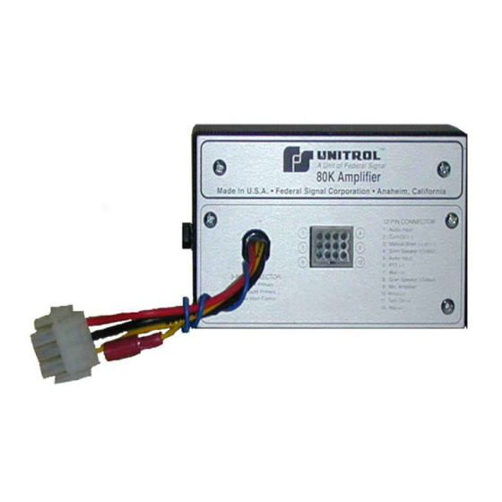
Summary of Contents for Federal Signal Corporation Unitrol 280 Series
- Page 1 MAN-80K REV. 14 FEB 03 80K AMPLIFIER Sirens Sirens with P.A. Sirens with P.A. and Switching INSTALLATION & OPERATION FS UNITROL * 1108 RAYMOND WAY * ANAHEIM, CA 92801 * (714)871-3336 * Fax (714)871-3418 WWW.UNITROL.COM...
- Page 2 Table of Contents Check Model Number of Unit to be Installed See Pages Listed Below that Apply Model 80K Amplifier Blowout Proof Transistors - Section I - pg. 1 Intrusion Alarm - Section VIII - pg. 9 Specifications - Section XI - pg. 12 Two-Tone Sounds - Section IX &...
-
Page 3: Section I - Basic System
SECTION I - BASIC SYSTEM Model 80K BLOW-OUT PROOF TRANSISTOR PROTECTION USED WITH ALL MODELS 1. Output transistors, blown out in normal sirens by Containing electronic components for generating failures of the siren speaker or its wiring are protected sounds, the Model 80K amplifier is the basic part in the Unitrol 80K by automatic circuitry. -
Page 4: Standard & Optional Features
SECTION II - KAWASAKI SIREN Model 80KM 3. Horn Button - The Kawasaki horn circuit is grounded (-) STANDARD & OPTIONAL FEATURES which must be inverted to +12V by a relay. Using 18ga. wire 1. Model U80KM consists of a UMCO83 cable for new connections, proceed as follows: and Model 80K Amplifier. -
Page 5: Amplifier Installation
SECTION III - BASIC SIREN SYSTEM Model 180K TOGGLE SWITCH INSTALLATION STANDARD & OPTIONAL FEATURES 1. Drill 15/32” hole. Make connections first. 1. System consists of a Model 180K toggle switch, CO29K cable and 80K Amplifier. HORN BUTTON or FOOT SWITCH 2. -
Page 6: Operation
SECTION IV- PUBLIC ADDRESS KITS For Models 80KM & 180K OPTIONAL PA KIT INSTALLATION 1. Models 80KM & 180K are shipped with cable 1. Locate area for jack installation. Allow 1” assemblies having four wires (Yellow, Gray, Green diameter clearance space for back portion of &... -
Page 7: Rear Connections
Section IV Cont. MODEL 183K REAR CONNECTIONS STANDARD & OPTIONAL FEATURES 1. B1 terminals from left to right are: 1. The system consists of a Model UM183K controller, a. Grd - Battery Ground a UM80K amplifier and a UCO30-4 cable, ( 4 foot b. - Page 8 SECTION V - SIREN/PA SYSTEM Operating Models 280K & 480K STANDARD & OPTIONAL FEATURES RADIO POWER CONTROL 1. All models perform essentially the same in that a Master 1. The two-way radio may be left “on” at all times. Switch turns the siren on and controls the vehicle horn ring. The rotary switch keeps it ignition-controlled in The horn ring and Unitrol rotary switch control siren sounds.
-
Page 9: Standard Equipment
SECTION VI SIREN /PA SYSTEM Installing Models 280K & 480K a) If two WHITE housing with male blades STANDARD EQUIPMENT exist, locate radio speaker. “T” into wires 1. System is housed in remote cabinetry as specified. that run between speaker and radio head All models include: with 18ga. - Page 10 SECTION VI & VII SIREN/ PA SYSTEMS Installing Models 280K & 480K (cont.) Model 280 - One Wire: 3 FOOT SWITCH Use wire for controlling lights. 1. A foot switch may be used in addition to or in place of the horn ring for siren controls. Model 480 - Five Wires: 1, 1-2, 1-2-3, 2-3, and 3.
-
Page 11: Section Viii - Intrusion Alarm
SECTION VIII - INTRUSION ALARM For All Models PURPOSE & OPERATION 1. The 80K amplifier is capable of producing a 1600 Hz. d) Connect remaining terminal of system steady tone. The tone can be used to warn out-of-vehicle on/off switch to positive output of motion driver that the vehicle or its contents are endangered. -
Page 12: Required Equipment
SECTION IX - TWO-TONE SYSTEMS For Model 180K REQUIRED EQUIPMENT PRELIMINARY CONNECTIONS 1. Control Unit- Any existing 180 system can be used. 1. Interconnect AIR HORN wires from both 3-pin No modifications or additional switches are needed. amplifier connectors using the appropriate connector. 2. - Page 13 SECTION X - TWO-TONE SYSTEMS For Models 280K & 480K REQUIRED EQUIPMENT PRELIMINARY CONNECTIONS 1. Control Unit - Any existing 280K or 480K 1. Interconnect AIR HORN wires from both 3 - pin control unit can be used. No modifications or amplifier connectors using the appropriate additional switches are required.
-
Page 14: Section Xi - General Information
SECTION XI - GENERAL INFORMATION AMPLIFIER SPECIFICATIONS Zero Standby Current Drain DETERMINING WIRE SIZE 800 Mils. Current Drain During PA 1. It is essential to proper siren and warning light 15A. Maximum siren current Drain @ 200 Watts operation to use wires large enough to carry the 58 to 200 Watts Siren Output (Switch Adjustable) load (amperes). -
Page 15: Section Xii - Warranty & Technical Support
SECTION XII - WARRANTY & TECHNICAL SUPPORT FIVE-YEAR WARRANTY & LIMITATIONS UNITROL products described in this Manual are warranted to be free from defects in material and workmanship for five years from installation date.Any product found to be faulty will, at the factory’s option after inspection, be replaced or repaired and returned without charge. - Page 16 SAFETY MESSAGE TO OPERATORS OF UNITROL ELECTRONIC SIRENS AND LIGHT/SOUND SYSTEMS Signaling Limitations WARNING Be aware that the use of your visual and audible The lives of people depend on your operation of signaling devices does not give you the right to force UNITROL products.
- Page 17 SAFETY MESSAGE TO INSTALLERS ELECTRONIC SIRENS Sound output will be severely reduced if any objects WARNING are in front of this speaker. If maximum sound output The lives of people depend on your safe installation is required for your application, you should ensure and servicing of UNITROL products.


Need help?
Do you have a question about the Unitrol 280 Series and is the answer not in the manual?
Questions and answers