Table of Contents
Advertisement
Advertisement
Table of Contents

Related Manuals for U.N.O Fitness LTX6 PRO

Summary of Contents for U.N.O Fitness LTX6 PRO
- Page 1 LTX6 PRO TREADMILL Art.-N .: 10055...
-
Page 2: Overview Drawing
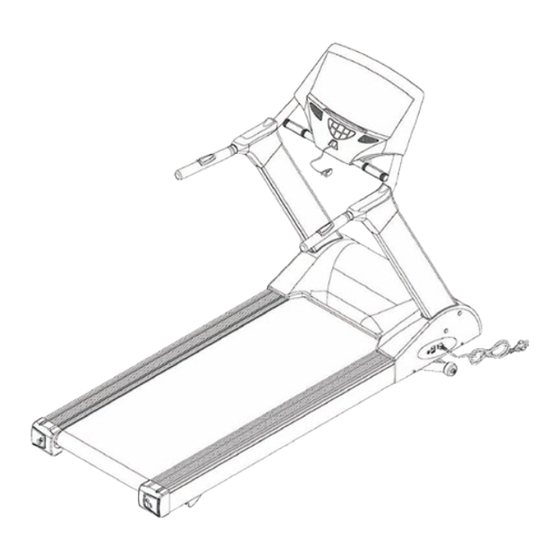
1. OVERVIEW DRAWING Computer Safety Key/Clip Frame Power Cord Power Cord Socket Power Switch Circuit Breaker 2011/5/16 Ver1.2+V1.0... -
Page 3: Important Safety Instructions
2. IMPORTANT SAFETY INSTRUCTIONS When using an electrical appliance, basic precautions should always be followed, including the followings: Read all instructions before using the treadmill. Danger – To reduce the risk of electric shock: Always unplug this appliance from the electrical outlet immediately after using and before cleaning. - Page 4 19. When user is using the treadmill, it cannot be folded at the same time. 20. Maximum user weight is 150 Kg. 21. The appliance is intended for household use only. 22. Place Customer Service Address (one of Manufacturer, Importer, Agent). Note —If the machine has folding function, before folding, make sure the inclination has come back to 0 (when folding, this can avoid the frameworks interfere each other).
-
Page 5: Grounding Instructions
3. GROUNDING INSTRUCTIONS 1. The products must be grounded first. If malfunction or breakdown occurs, grounding will provide a path of least resistance for electric current to reduce the risk of electric shock. 2. The product is equipped with a cord having an equipment-grounding conductor and a grounding plug. -
Page 6: Pre-Assembly Check List
4. PRE-ASSEMBLY CHECK LIST Instructions of product fittings 1. This treadmill can detect pulse value through other ways. When you are exercising, bind chest pulse in front of your chest and then you will see your pulse value in PULSE window. 2. -
Page 7: Assembly Steps
5. ASSEMBLY STEPS Two persons are required to finish the assembly steps. (Caution!! Please follow exactly the assemly steps below to aviod injury . ) After pull out Control Wire with Guide Thread in the Upright, cap it into the hole of the Upright. - Page 8 Put the Computer Console which has been assembled in above step on the assembled Frame. Connect control wire of Computer with Frame and fix with Allen Bolt (b). Cap Upper Handrail Covers (L) (R) (G, H) on the computer tube and fix with Self Tapping Screw (e).
- Page 9 To assemble the Bottle Holder:Put Bottle Holder (I) on the right Upright (D) and aim at the hole. Fix with Screw (d). 2011/5/16 Ver1.2+V1.0...
-
Page 10: Maintenance
6. MAINTENANCE If the running belt tends to move off central during operation, stop the treadmill. Take the T-shaped Wrench and adjust the Allen Bolt in the left Rear End Cap. If the running belt is moving towards the right side, tighten the Allen Bolt about 1/4 of turn (clockwise). -
Page 11: Add Silicone
7. ADD SILICONE Time of add SILICONE When suggested time of adding SILICONE is achieved, please extend your hand to the center of the running board to make sure whether there is any SILICONE before adding. If no SILICONE on the running board, please add 30cc SILICONE to the running board. If there is still a little SILICONE, add 15cc SILICONE to the running board. - Page 12 Power Saving Mode When the treadmill not work for 4 minutes, it will enter power saving mode and at this time, the meter will not show anything. Caution If you want to use treadmill, please take off the safety key (1-1)and take it back to original place(2-1), then make the treadmill back to start/steady mode.
-
Page 13: Computer Instructions
8. COMPUTER INSTRUCTIONS I. Start Display: 1. After power on, the window will display floating string PRESS WEIGHT BUTTON TO SET WEIGHT. Press WEIGHT, and blue back light LCD displays weight unit. After finish setting, press ENTER and blue back light LCD displays heartbeat picture. The floating string in the window displays SELECT PROGRAM OR START. - Page 14 II. Operation Instruction: : : : 1. Under Start/Ready position, press Start to enter directly by pressing Manu run. 2. Under Start/Ready position, press PROGRAM function key to enter the edit. 3. When the SAFETY KEY is taken off and then replaced, it will not make reposition action any where it is.
- Page 15 5. During exercise, if there is PULSE signal, CALORIES window will display pulse. 6. Press Stop when the motor is working, the motor will stop and the incline motor will stop, the window will display Stop; If you press START key again, the motor will start after 3-seconds countdown , the speed will be keep at the same before stop , and the incline will be increased to the set height before stop .
- Page 16 according to pre-set value and turn to next position. 4. TIME window starts flashing; mode will request you to put in time value. You can press to set sport time you need. Or press directly to start move with count down.
- Page 17 ** If it has any error signal, please connect with the sale agent. ◆ E6 / E7 Incline Function Abnormity Simple Exclusion Action 1. Restart the treadmill and E6 or E7 signal appears, please check follow the second step. 2. Force incline ascend or descend to test whether the incline motor and the wire of transmission signal is normal.
- Page 18 (Drawing 2) 3. If you have tried the above steps and still can’t solve the malfunction of incline function, please contact with technology repairer of your dealer. At this time, you should emphasize that the inline function can’t work. To make users operate the treadmill with no incline function, you can press STOP and hold it, then press slowdown key(-).
- Page 19 SPEED AND ELEVATION CHANGES 9 HOLE Level 1 ELEVATION (MPH) (KPH) Level 2 ELEVATION (MPH) (KPH) Level 3 ELEVATION (MPH) (KPH) Level 4 ELEVATION (MPH) (KPH) Level 5 ELEVATION (MPH) (KPH) Level 6 ELEVATION (MPH) (KPH) Level 7 ELEVATION (MPH) (KPH) Level 8 ELEVATION...
- Page 20 SPEED AND ELEVATION CHANGES HILL CLIMB Level 1 ELEVATION (MPH) (KPH) Level 2 ELEVATION (MPH) (KPH) Level 3 ELEVATION (MPH) (KPH) Level 4 ELEVATION (MPH) (KPH) Level 5 ELEVATION (MPH) (KPH) Level 6 ELEVATION (MPH) (KPH) 10.4 10.4 10.4 10.4 10.4 10.4 10.4...
- Page 21 SPEED AND ELEVATION CHANGES HILL RUN Level 1 ELEVATION (MPH) (KPH) Level 2 ELEVATION (MPH) (KPH) Level 3 ELEVATION (MPH) (KPH) Level 4 ELEVATION (MPH) (KPH) Level 5 ELEVATION (MPH) (KPH) Level 6 ELEVATION (MPH) (KPH) 10.4 10.4 10.4 10.4 10.4 10.4 10.4...
- Page 22 SPEED CHANGES ONLY INTERVAL (MPH) Level 1 (KPH) (MPH) Level 2 (KPH) (MPH) Level 3 (KPH) (MPH) Level 4 (KPH) (MPH) Level 5 (KPH) (MPH) Level 6 (KPH) (MPH) Level 7 (KPH) 10.4 10.4 10.4 10.4 10.4 10.4 10.4 10.4 10.4 10.4 10.4...
- Page 23 SPEED CHANGES ONLY ROLLING (MPH) Level 1 (KPH) (MPH) Level 2 (KPH) (MPH) Level 3 (KPH) (MPH) Level 4 (KPH) (MPH) Level 5 (KPH) (MPH) Level 6 (KPH) 10.4 10.4 10.4 10.4 10.4 10.4 10.4 10.4 10.4 (MPH) Level 7 (KPH) 10.4 11.2...
- Page 24 SPEED CHANGES ONLY WEIGHT LOSS (MPH) Level 1 (KPH) (MPH) Level 2 (KPH) (MPH) Level 3 (KPH) (MPH) Level 4 (KPH) (MPH) Level 5 (KPH) (MPH) Level 6 (KPH) (MPH) Level 7 (KPH) 10.4 10.4 10.4 10.4 (MPH) Level 8 (KPH) 10.4 10.4...
- Page 26 LTX6 PRO Treadmill Part List description q'ty NO description q'ty 1 Computer Console 53 Allen Screw M8xP1.25x115 25mm 2 Safety Key Set 54 Aluminum Pedal Fixing Plate 3 Truss Hex Screw(ψ13) K-299 55 Aluminum Pedal 4 Lower Control Wire 5 Upper Handrail Cover (Left)
- Page 27 Transducer Set (3.0Hp,220V) RM5T-2003 81A Hex Wrench + Screwdriver 5mm ningmao Transducer power cord (according BOM) Transducer Control wire 83 Chest Belt Pulse Emitter 33 Hex Nut M10xP1.5 34 Truss Hex Screw M8xP1.25x40 35 Truss Philips Screw M5xP0.8x15 36 Power Cord 37 Power Cord Socket 88B Round Head Philips Screw(Galvanization)M 4 38 Power Switch...
Need help?
Do you have a question about the LTX6 PRO and is the answer not in the manual?
Questions and answers