Table of Contents
Advertisement
Quick Links
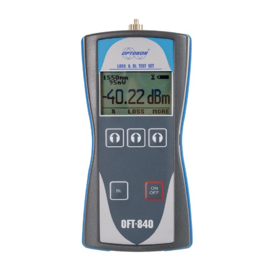
OFT-840
Loss Test Set
INSTRUCTION MANUAL
Revision 1.1
is registered trademark of OPTOKON, a.s. Other names and trademarks mentioned herein may be the
trademarks of their respective owners.
OPTOKON, a.s., Cerveny Kriz 250, 586 01 Jihlava, Czech Republic
tel. +420 564 040 111, fax +420 564 040 134, WWW.OPTOKON.COM, INFO@OPTOKON.CZ
27/10/2017
Advertisement
Table of Contents

Related Manuals for OPTOKON OFT-840

Summary of Contents for OPTOKON OFT-840
- Page 1 Loss Test Set INSTRUCTION MANUAL Revision 1.1 is registered trademark of OPTOKON, a.s. Other names and trademarks mentioned herein may be the trademarks of their respective owners. OPTOKON, a.s., Cerveny Kriz 250, 586 01 Jihlava, Czech Republic tel. +420 564 040 111, fax +420 564 040 134, WWW.OPTOKON.COM, INFO@OPTOKON.CZ...
- Page 2 OPTOKON, a.s. Other names and trademarks mentioned herein may be the trademarks of their respective owners All rights reserved. No parts of this work may be reproduced in any form or by any means - graphic, electronic, or mechanical, including photocopying, recording, taping or information storage and retrieval systems - without the written permission of the publisher.
-
Page 3: Table Of Contents
OFT-840 INSTRUCTION MANUAL Contents Introduction ....................4 Features ...................... 4 Application ....................4 Accessories ....................5 Standard ........................5 Optional ........................5 Specifications ....................6 Safety information ..................7 ... -
Page 4: Introduction
OFT-840 INSTRUCTION MANUAL 1 Introduction The OFT-840 series optical Loss Test Set with optical Return Loss (RL) combines optical Light Source, Power Meter and Return Loss testing in the same box. The optical Light Source fulfills all the necessary technical requirements for field equipment. -
Page 5: Accessories
OFT-840 INSTRUCTION MANUAL 4 Accessories 4.1 Standard SmartProtocol PC software USB connection cable PM: Universal 2.5 mm adapter LS+RL: adapter FC/APC Master patchcords: FC/APC – FC/APC (master at both ends) Master measuring adapters: FC/APC ... -
Page 6: Specifications
OFT-840 INSTRUCTION MANUAL 5 Specifications General specifications Note: Dimensions 165 x 80 x 50 mm with 2.5 mm universal adapter Weight 400 g with battery Temperature operating -10 to +50 °C storage -40 to +70 °C Humidity (non condensing) 0 to 95% Operating temperature -10 to +50 °C... -
Page 7: Safety Information
WARNING! The OFT-840 Power meter emits no optical power itself and does not create any hazards to the user. To ensure a high level of operator safety during installation, commissioning and... -
Page 8: Maintenance
Charge the batteries fully before storing the tester for a long period. The batteries will lose its capacity during storage. If you are not going to use the OFT-840 for long period, charge the batteries once every six months. -
Page 9: Recommended Cleaning And Mating Instructions
OFT-840 INSTRUCTION MANUAL 7.3 Recommended cleaning and mating instructions Cleanliness will affect the performance of an residual alcohol. For oversized adapters optical fiber system. Perform the following (biconic), slightly blow the middle of the pipe procedures prior the installation. Clean all cleaner fog better surface contact. -
Page 10: Light Source Adaptor Set Exchange
OFT-840 INSTRUCTION MANUAL 7.4 Light source Adaptor set exchange The OFT-840 comes equipped with an adaptor set (FC or SC adaptor). The adaptor set includes: adaptor body with flange two screws adaptor sleeve adaptor nut. For exchanging the adaptor or cleaning the ferrule end face please use the following instructions: 1. - Page 11 OFT-840 INSTRUCTION MANUAL 3. Loosen the two adaptor flange screws 4. Carefully remove the adaptor body, be careful of the sleeve 5. Using the optical connector ferule, carefully remove the adapter sleeve...
- Page 12 OFT-840 INSTRUCTION MANUAL 6. Remove the adaptor nut. Now the adaptor set is fully removed. If necessary, carefully clean the ferrule end face using alcohol and lint-free laboratory wipes. 7. Insert the adaptor nut and the sleeve back. 8. Attach the appropriate adaptor body and tighten the screws again...
-
Page 13: Instrument And Button Function Description
OFT-840 INSTRUCTION MANUAL 8 Instrument and button function description 8.1 General description Power meter and Light souce / Return loss meter ports LCD display Operating buttons USB port ON/OFF button Backlight key [ON/OFF] Press to turn the unit on. Press to turn the unit off. -
Page 14: Power Meter
OFT-840 INSTRUCTION MANUAL 8.2 Power meter 8.2.1 Menu #1 –Absolute power measurement mode In the absolute power measurement mode the absolute value of the optical signal in dBm units is shown on the display. This screen will appear after the instrument is switched on and information regarding the type of device, serial number and firmware version will appear. -
Page 15: Menu #2 - Relative Power Measurement Mode
OFT-840 INSTRUCTION MANUAL 8.2.2 Menu #2 – Relative power measurement mode In the relative power measurement mode is on the value of optical insertion loss in dB units which corresponds to performed reference is shown on the display. Reading the display:... -
Page 16: Menu #3 - Navigation
OFT-840 INSTRUCTION MANUAL 8.3 Menu #3 – Navigation [LS] Goes to Light source menu#4. [ORL] Goes to Return loss mode menu#5. [MEM] Goes to Memory menu #6. Starts working with the internal memory. -
Page 17: Light Source
OFT-840 INSTRUCTION MANUAL 8.4 Light source 8.4.1 Menu #4 – Light source menu Reading the display: battery status 1550 nm LS OFF indicator [] active output port light source required wavelength settings. [MOD] Selects the modulation: CW – Continuous wave 270 Hz –... -
Page 18: Orl - Optical Return Loss Meter
OFT-840 INSTRUCTION MANUAL 8.5 ORL – Optical Return Loss meter 8.5.1 Menu #5 – ORL Master patchcord with APC connectors Master patchcord with PC connector No reflection Reflection from open port fiber - air [] Return loss meter required wavelength settings. -
Page 19: Menu #6 - Internal Memory Operation
OFT-840 INSTRUCTION MANUAL 8.6 Menu #6 – Internal memory operation The memory of OFT-840 has a structured, two-level organization. The results are stored in memory positions (FIBER) in folders called Cable (CABLE). See table below: CABLE001 FIBER001 FIBER002 FIBER003 FIBER004... -
Page 20: Save Result
OFT-840 INSTRUCTION MANUAL 8.6.1 SAVE RESULT 1. By using [UP] [DOWN] select “SAVE RESULT” and press [OK]. CABLE 001 FIBER 004 STORED : 003 - CABLE + FIBER 2. Select the cable (folder) using [- CABLE +], the unit will display the number of saved results under the selected cable, then press [FIBER]. -
Page 21: Browse Results
OFT-840 INSTRUCTION MANUAL 8.6.2 BROWSE RESULTS 1. By using [UP] [DOWN] select “BROWSE RESULTS” and press [OK] CABLE 001 STORED : 003 - CABLE + FIBER 2. Select the cable (folder) using [- CABLE +], the unit will display the number of saved results under the selected cable, then press [FIBER]. -
Page 22: Erase Memory
OFT-840 INSTRUCTION MANUAL 8.6.4 ERASE MEMORY 1. By using [UP] [DOWN] select “ERASE MEMORY” and press [OK]. ERASE MEMORY ERASE MEMORY CONFIRM CONFIRM 2. Press [CONFIRM] to erase memory or [NO] for return to main screen. 8.6.5 HOME 1. By using [UP] [DOWN] select “HOME”. -
Page 23: Measuring Loss
The test is based on measurement the power difference at the input and output of the link. One or two units OFT-840 are used for this test, where Light source port is acting as transmitter and Optical power meter port as receiver. - Page 24 OFT-840 INSTRUCTION MANUAL Important All connectors and fiber end faces should be cleaned prior to testing (see chapter 7.3). The master cord used to set the reference should be the same type as the patchcords (cables) to be tested (MM:50/125, 62.5/125 or SM).
-
Page 25: Method 6 - Two Instruments
9.2.1 Setting the reference 1. Connect first Master cord to Light source port of first OFT-840 instrument. 2. Connect second Master cord to Power meter port of second OFT-840 instrument. 3. Use Master adaptor to connect the two fiber ends. -
Page 26: Measuring Loss
OFT-840 INSTRUCTION MANUAL pic.2 9.2.2 Measuring Loss 1. Do not disconnect the Master cords from instruments. 2. Disconnect one Master cord from adaptor. 3. Connect the trace to be measured between the Master cords. An extra Master adaptor is needed. -
Page 27: Method 6 - One Instrument
1. Connect first Master cord to Light source port. 2. Connect second Master cord to Power meter port. 3. Use Master adaptor to connect the two fiber ends. 4. Power on OFT-840 instrument. 5. Push [MORE], [LS]. 6. By pushing [] activate appropriate wave-length (light source). -
Page 28: Measuring Loss
OFT-840 INSTRUCTION MANUAL 9.3.2 Measuring Loss pic.4 1. Do not discconect the Master cords from instrument. 2. Disconnect one Master cord from adaptor. 3. Connect the trace to be measured between the Master cords. An extra Master adaptor is needed. -
Page 29: Method 7 - Two Instrument
9.4.1 Setting the reference 1. Connect Master cord to Light source port of first OFT-840 instrument. 2. Connect second end of Master cord to Power meter port of second OFT-840 instrument. 3. Power on first OFT-840 instrument (light source). -
Page 30: Measuring Loss
OFT-840 INSTRUCTION MANUAL 9.4.2 Measuring Loss pic.6 1. Do not discconect the Master cord from Light source port. 2. Connect the trace to be measured between the Power meter port and the Master cord that is attached to Light source. An extra Master adaptor is needed. -
Page 31: Method 7 - One Instrument
9.5.1 Setting the reference 1. Connect Master cord to Light source port. 2. Connect second end of Master cord to Power meter port. 3. Power on OFT-840 instrument. 4. Push [MORE], [LS]. 5. By pushing [] activate appropriate wave-length (light source). -
Page 32: Measuring Loss
OFT-840 INSTRUCTION MANUAL pic.8 9.5.2 Measuring Loss 1. Do not discconect the Master cord from Light source port. 2. Connect the trace to be measured between the Power meter port and the Master cord that is attached to Light source. An extra Master adaptor is needed. -
Page 33: Measuring Reflectance Or Return Loss
OFT-840 INSTRUCTION MANUAL 10 Measuring Reflectance or Return loss Reflectance Reflectance or optical return loss (which has also been called "back reflection") of a connection is the amount of light that is reflected back up the fiber toward the source by light reflections off the interface of the polished end surface of the mated connectors and air. -
Page 34: Setting Up Data Transfer
OFT-840 INSTRUCTION MANUAL 11 Setting up data transfer 1. Connect the OFT-840 to a PC using the USB cable provided and turn the OFT-840 on. The PC will prompt you to install the drivers for new hardware. Use the drivers provided by OPTOKON. These drivers will create a virtual serial com port. - Page 35 OFT-840 INSTRUCTION MANUAL 4. Choose the virtual serial port the OFT-840 is connected to, then click on OK OFT-820 5. Set “Bits per second” to 19200, then click on OK...
- Page 36 OFT-840 INSTRUCTION MANUAL 6. Go to the menu in OFT-840 and push [MORE], [MEM], select [UPLOAD MEMORY], [OK]. The stored data will be transferred to the PC in this format: stored values fiber wavelength position cable folder The data from this window can be easily copied to any other application.
-
Page 37: Power Loss And Decibels
OFT-840 INSTRUCTION MANUAL 12 Power loss and decibels Loss (dB) % Loss Power (mW) 0.00001 0.0001 0.001 0.01 0.10 10.9 0.13 12.9 0.16 14.9 0.20 16.8 0.25 18.7 0.32 20.6 0.40 36.9 0.50 49.9 0.63 60.2 0.79 68.4 1.00 74.9 1.26... -
Page 38: Notes
OFT-840 INSTRUCTION MANUAL 13 Notes ................................................................................................................................................................................................................................................................................................................................................................................................................ -
Page 39: Calibration, Service Center
14 Calibration, service center OPTOKON, a.s. Červený Kříž 250 586 01 Jihlava Czech Republic tel.: +420 564 040 111 fax: +420 564 040 134 optokon@optokon.com www.optokon.com...
Need help?
Do you have a question about the OFT-840 and is the answer not in the manual?
Questions and answers