
Related Manuals for AIRSYS UNICOOL 11V1T3

Summary of Contents for AIRSYS UNICOOL 11V1T3
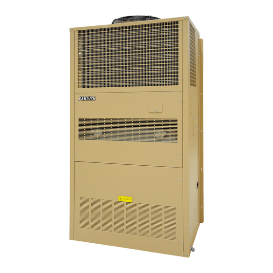
- Page 1 Wall Packaged Unit Air Conditioners Installation and Operation Manual Unit Models 11V1T3 11V1B3 15V1T4 15V1B4 28V1B5 28V2B5 Controller Model ASMUC.6 ASMUC.6.AC ASMUC.6.DC...
- Page 2 AIRSYS. The information contained in this document is subject to change without notice. AIRSYS provides this material as is and makes no warranty of any kind, expressed or implied, including, but not limited to, the implied warranties of merchantability and fitness for a particular purpose. AIRSYS...
-
Page 3: Table Of Contents
Warranty ..................................... 15 Moving the Unit ..................................15 General Safety Rules ................................16 ..................................16 EQUIRED ATERIALS AIRSYS Supplied Materials ..............................16 Materials Supplied by Installer ............................17 Electrical Ratings (Wire Sizing) ............................19 ................................... 20 HYSICAL NSTALLATION Select the Wall for Installing the Unit ..........................20 Clearances .................................... - Page 4 Viewing Controller Information ............................56 Viewing Unit Information ..............................57 ..................................... 59 ROGRAM ENUS ......................................60 ......................................61 LARMS Alarm History .................................... 63 Contact: AIRSYS North America Phone: (855) 874-5380 Page 4 of 112 Email: ASNSupport@air-sys.com Web: http://airsysnorthamerica.com Rev 1.15...
- Page 5 CHAPTER 8: SPARE PARTS ........................95 APPENDIX A: AIR FRAME DRAWING ....................... 96 APPENDIX B: WIRING DIAGRAMS ......................97 APPENDIX C: MECHANICAL DRAWINGS ....................104 Contact: AIRSYS North America Phone: (855) 874-5380 Page 5 of 112 Email: ASNSupport@air-sys.com Web: http://airsysnorthamerica.com...
- Page 6 APPENDIX D: LIST OF TABLES ........................ 110 APPENDIX E: LIST OF FIGURES ....................... 111 Contact: AIRSYS North America Phone: (855) 874-5380 Page 6 of 112 Email: ASNSupport@air-sys.com Web: http://airsysnorthamerica.com Rev 1.15...
-
Page 7: Chapter 1: Introduction
Real-time power monitoring for individual units • The AIRSYS UNICOOL WPUs are available in cooling capacities from 1.5 - 10 tons; however, the sensible cooling capacity of these machines is as much as 40% higher than a traditional machine. An available ordering guide can help properly match the capacity of the HVAC system to the heat load in the shelter. -
Page 8: Using This Manual
• For safety and to achieve the highest levels of performance, always follow the warnings and cautions in this manual when handling and operating the AIRSYS unit. Danger. Emphasizes hazardous conditions that could cause personal injury or death. Warning. Indicates where the operator must proceed with caution to avoid personal injury or damage to property. -
Page 9: Model Identification
Each unit is identified by a model number, such as 11V1T3MR410AAC. The elements in the number are explained in Figure 1: Model Number Figure 1: Model Number Contact: AIRSYS North America Phone: (855) 874-5380 Page 9 of 112 Email: ASNSupport@air-sys.com Web: http://airsysnorthamerica.com... -
Page 10: Acronyms And Abbreviations
Table 2 lists acronyms and abbreviations used in this manual. Table 2: Acronyms and Abbreviations Term Meaning Ampere, unit of electric current, or rate of flow of electricity AAST AIRSYS Authorized Service Technician Alternating Current AFPD Air Filter Protection Device AUT/MAN Automatic/Manual... -
Page 11: Chapter 2: Product Overview
Mechanical Cooling Mode Free Cooling Mode Figure 2: Operating Modes (Top Supply) Free Cooling Mode Mechanical Cooling Mode Figure 3: Operating Modes (Bottom Supply) Contact: AIRSYS North America Phone: (855) 874-5380 Page 11 of 112 Email: ASNSupport@air-sys.com Web: http://airsysnorthamerica.com Rev 1.15... -
Page 12: Free Cooling System
The Control System (ASMUC.6 Controller) By default, the ASMUC.6 controller can control up to 6 AIRSYS Precision Cooling WPUs (16 with expansion module) organized in up to 4 zones. The setpoint for each zone can be adjusted independently. -
Page 13: Ease Of Control And Configuration
Quiet mode reduces noise by 10-14 dBA by limiting the maximum speed that the compressor can run at. In doing so, the maximum cooling capacity will be reduced by ~15% and Turbo Boost will be disabled. Contact: AIRSYS North America Phone: (855) 874-5380 Page 13 of 112 Email: ASNSupport@air-sys.com... -
Page 14: Chapter 3: Installation
Danger. All the installation work must be done by professional technicians. Installation that does not comply with the instructions herein can result in the loss of warranty coverage. AIRSYS shall not be held liable for any damage caused to persons or objects due to incorrect installation or operation of the units. -
Page 15: Warranty
Without the detailed photos, it will be very difficult to recover equipment loss. Warranty The warranty duration is 12 months from the date of installation. AIRSYS warrants that its products will be free from defects in materials and workmanship for a period of 12 months after installation. -
Page 16: General Safety Rules
AIRSYS Supplied Materials Table 3: AIRSYS Provided Materials lists all material supplied by AIRSYS. After opening the package, verify that all items are accounted for. If any material is missing, please contact an AIRSYS distribution center using the following information:... -
Page 17: Materials Supplied By Installer
1021006360 Materials Supplied by Installer Table 4 lists items required for installation that must be supplied by an AIRSYS Authorized Service Technician (AAST). The wire length and gauge depend on site-specific conditions. However, recommendations are provided. Contact: AIRSYS North America... - Page 18 HVAC units. If 1 per unit (Optional) HVAC unit not supplied at install, a return trip is required to establish communication. Contact: AIRSYS North America Phone: (855) 874-5380 Page 18 of 112 Email: ASNSupport@air-sys.com Web: http://airsysnorthamerica.com Rev 1.15...
-
Page 19: Electrical Ratings (Wire Sizing)
28V1B5MR410BAC 28V1B5MR410CAC Table 6: Controller Electrical Ratings Model Power Source Max Power Max Current ASMUC.6 48VDC 1.0A ASMUC.6.DC 24VDC/48VDC 1.3A/0.6A ASMUC.6.AC 120VAC 0.75A Contact: AIRSYS North America Phone: (855) 874-5380 Page 19 of 112 Email: ASNSupport@air-sys.com Web: http://airsysnorthamerica.com Rev 1.15... -
Page 20: Physical Installation
12 in 6 in tube. Bottom (300 mm) (150 mm) NOT needed for 28V1 due to support stand mounting. Contact: AIRSYS North America Phone: (855) 874-5380 Page 20 of 112 Email: ASNSupport@air-sys.com Web: http://airsysnorthamerica.com Rev 1.15... -
Page 21: Pouring The Concrete Pad (28V1B5 Only)
Figure 4: Openings and Holes in the Wall (Bottom Supply) Cabinet Size 34-5/8 39-5/16 10-9/16 10-9/16 9-7/16 12-3/16 8-1/4 43-7/16 1104 43-7/16 1104 34-15/16 11-9/17 Contact: AIRSYS North America Phone: (855) 874-5380 Page 21 of 112 Email: ASNSupport@air-sys.com Web: http://airsysnorthamerica.com Rev 1.15... - Page 22 Figure 5: Openings and Holes in the Wall (Top Supply) Cabinet Size 29-3/4 29-3/4 9-11/16 9-11/16 15-11/16 15-11/16 30-1/4 30-1/4 Contact: AIRSYS North America Phone: (855) 874-5380 Page 22 of 112 Email: ASNSupport@air-sys.com Web: http://airsysnorthamerica.com Rev 1.15...
-
Page 23: Install Weather Stripping
The unit must be installed in a level position. An inclination of more than 6-7 mm (± 1° ) may cause the condensation tray to overflow (Figure 7). Figure 7: Inclination of Mounted WPU Contact: AIRSYS North America Phone: (855) 874-5380 Page 23 of 112 Email: ASNSupport@air-sys.com... -
Page 24: Remove Wooden Pallet From Wpu
Support stands should be installed on all 28V1B5 units due to the heavy weight. Place the support stand on the concrete pad, flush against the wall, and extend the legs to the desired length. Contact: AIRSYS North America Phone: (855) 874-5380 Page 24 of 112 Email: ASNSupport@air-sys.com... -
Page 25: Seal The Joints Between Wpus And Wall
1. Install the supply and return air frames (and exhaust air frame for 28V1) into their respective cutouts. 2. Use adhesive tape to tape down the edges of the return and supply air frames on the WPU side. Contact: AIRSYS North America Phone: (855) 874-5380 Page 25 of 112 Email: ASNSupport@air-sys.com... -
Page 26: Remove The Compressor Brackets
Remove the two brackets, then refasten the bolts Figure 12: Remove Compressor Brackets Contact: AIRSYS North America Phone: (855) 874-5380 Page 26 of 112 Email: ASNSupport@air-sys.com Web: http://airsysnorthamerica.com... -
Page 27: Controller Box Installation
Find a suitable location inside the shelter to mount the controller box. Mount the controller box so that the PGD is near the eye level of the intended operator. Figure 13: Controller Box Dimensions Contact: AIRSYS North America Phone: (855) 874-5380 Page 27 of 112 Email: ASNSupport@air-sys.com... -
Page 28: Install Outdoor Temperature Sensor
2. Drill a 1/2-inch diameter hole for the outdoor temperature sensor (ST3) through the shelter wall. 3. Open the controller box assembly and locate the outdoor temperature sensor (ST3) assembly. Contact: AIRSYS North America Phone: (855) 874-5380 Page 28 of 112 Email: ASNSupport@air-sys.com... - Page 29 Important. Ensure no air leakage exists from inside the shelter to the box housing the outdoor temperature sensor. Any path whereby air could exit the shelter and arrive in the sensor box will adversely affect the outdoor temperature sensor reading. Contact: AIRSYS North America Phone: (855) 874-5380 Page 29 of 112 Email: ASNSupport@air-sys.com...
-
Page 30: Position The Humidity Sensor
WPU operation. Slide the sensor through the port on the bottom left side of the controller box. Tighten the port cover to hold the sensor cable in place. Figure 15: Position the Indoor Temperature Sensor Contact: AIRSYS North America Phone: (855) 874-5380 Page 30 of 112 Email: ASNSupport@air-sys.com... -
Page 31: Complete Electrical Connections
Not following instructions can void the warranty. Important. No modification to the unit’s electric circuit is allowed. If a change is required, it must be authorized by AIRSYS in writing. Output Alarms Output alarms are dry contract outputs from the ASMUC to a remote monitoring block/station. Consult the ASMUC wiring diagram in Appendix B for wiring locations. -
Page 32: Input Alarms
Normally Open (NO), which can be changed to Normally Closed (NC) in the “Alarms” menu under the Control Config Menu. Contact: AIRSYS North America Phone: (855) 874-5380 Page 32 of 112 Email: ASNSupport@air-sys.com... -
Page 33: Electrical Connection To Controller Box
(Behind J12). Important. Do not run the Ethernet cables in the same conduit as prime power or other high voltage AC as this can result in communication errors. Contact: AIRSYS North America Phone: (855) 874-5380 Page 33 of 112 Email: ASNSupport@air-sys.com... -
Page 34: Supplying Power To Wpus
Prime power connections to WPU 48VDC power connections to WPU (If applicable) 2. Ground the system using ground lug or ground terminal. Contact: AIRSYS North America Phone: (855) 874-5380 Page 34 of 112 Email: ASNSupport@air-sys.com Web: http://airsysnorthamerica.com Rev 1.15... -
Page 35: Complete The Installation Checklist
The power connections between the controller box and power plant panel are secured. Proper clearance is allowed between the cables and air damper in the WPU to avoid interference. Contact: AIRSYS North America Phone: (855) 874-5380 Page 35 of 112 Email: ASNSupport@air-sys.com... -
Page 36: System Commissioning
Press Down, the screen should display “No Conversion”. Press Enter until the cursor is on the row below “Current UoM” Press Up or Down until the desired unit conversion is shown and press Enter. Contact: AIRSYS North America Phone: (855) 874-5380 Page 36 of 112 Email: ASNSupport@air-sys.com... -
Page 37: Set Ip Addresses For Controller (Optional For Remote Monitoring)
Gateway and DNS: Use values specified by end user or leave at 0.0.0.0 6. Press Enter until the cursor is over “Update Config” and press Up to change “No” to “Yes”. 7. Press Enter. Contact: AIRSYS North America Phone: (855) 874-5380 Page 37 of 112 Email: ASNSupport@air-sys.com... -
Page 38: Remove The Pgd From The Controller (If External Display Not Available)
1. Connect a PGD to the control module inside the unit using the preinstalled connector. 2. Hold the Esc button until the main screen is displayed. 3. Hold Alarm and Enter for 3 seconds to enter the hardware configuration menu. Contact: AIRSYS North America Phone: (855) 874-5380 Page 38 of 112 Email: ASNSupport@air-sys.com... -
Page 39: Verify The Unit Model Number
Press Down until the cursor is over “Serial Number”, the press Enter. Use the Up and Down buttons to change each digit of the serial number and press Enter to move to the next number. Contact: AIRSYS North America Phone: (855) 874-5380 Page 39 of 112 Email: ASNSupport@air-sys.com... -
Page 40: Set The Number Of Units And Zones
“rotate”, even for single unit zones. If the unit is set to standalone, it will stay on unless turned off from the unit itself. 10. Repeat steps 6-9 for all units. Contact: AIRSYS North America Phone: (855) 874-5380 Page 40 of 112 Email: ASNSupport@air-sys.com... -
Page 41: Match Unit Id With Ip Address
2. Press Down until a power icon is displayed in the lower right corner of the display. 3. Press Enter. 4. Press Up until ON is displayed and then press Enter. Figure 19: On/Off Screen Contact: AIRSYS North America Phone: (855) 874-5380 Page 41 of 112 Email: ASNSupport@air-sys.com Web: http://airsysnorthamerica.com... -
Page 42: Execute The Step-Test
Press Down, the screen should display “Test settings”. Press Enter until the desired component is selected. Press Up or Down to adjust the speed and press Enter. Contact: AIRSYS North America Phone: (855) 874-5380 Page 42 of 112 Email: ASNSupport@air-sys.com Web: http://airsysnorthamerica.com... -
Page 43: Set The System Clock
5. If multiple zones have been established, press Enter until the cursor is in the upper left corner and press Down to access the settings for each zone. 6. Repeat steps 3-5 until the settings for each zone have been entered. Contact: AIRSYS North America Phone: (855) 874-5380 Page 43 of 112 Email: ASNSupport@air-sys.com... -
Page 44: Verify Input And Output Alarms
47 and 48. b. HVAC3: Turn off the HVAC 3 prime power breaker at panel or unit. Verify alarm signal between terminals 47 and 49. Contact: AIRSYS North America Phone: (855) 874-5380 Page 44 of 112 Email: ASNSupport@air-sys.com Web: http://airsysnorthamerica.com... -
Page 45: Clear The Alarm History
To add additional recipients, press Enter until the cursor is in the upper left corner and press Down to access the IP settings for the other recipients. Repeat steps 7-10 as needed. Up to 5 recipients can be added. Contact: AIRSYS North America Phone: (855) 874-5380 Page 45 of 112 Email: ASNSupport@air-sys.com... -
Page 46: Complete The Registration Card
The following pictures show serial number locations for the WPU and control box. The nameplates can be found on the outside of the WPU and on the front of the controller box. These must be recorded on the AIRSYS Product Warranty Registration Card. The registration card can also be submitted online at https://airsysnorthamerica.com/support/warranty-registration/. - Page 47 Verify HVAC Alarms (if installed) Verify DC-Failover (Optional) Clear Alarm History Fill out Warranty Card and send to AIRSYS North America Contact: AIRSYS North America Phone: (855) 874-5380 Page 47 of 112 Email: ASNSupport@air-sys.com Web: http://airsysnorthamerica.com Rev 1.15...
- Page 49 AIRSYS PRODUCT WARRANTY REGISTRATION CARD PRODUCT INFORMATION Controller Model #: ________________________ Serial #: _________________________ HVAC #1 Model #: ________________________ Serial #: _________________________ HVAC #2 Model #: ________________________ Serial #: _________________________ HVAC #3 Model #: ________________________ Serial #: _________________________ HVAC #4...
-
Page 51: Chapter 4: System Operation
For this section, “controller” will refer to the ASMUC.6 controller box and “system” will refer to the controller AND all connected units. Contact: AIRSYS North America Phone: (855) 874-5380 Page 51 of 112 Email: ASNSupport@air-sys.com Web: http://airsysnorthamerica.com... -
Page 52: Navigating Menus
Main Screen The Main Screen is displayed by default upon system startup. It can also be accessed from any point by holding the Esc button. Contact: AIRSYS North America Phone: (855) 874-5380 Page 52 of 112 Email: ASNSupport@air-sys.com Web: http://airsysnorthamerica.com... -
Page 53: Turning The System On And Off
2. Press Up or Down until the power icon is displayed in the bottom right of the screen and press Enter. 3. Press Up or Down to switch between On and Off, press Enter to confirm. Contact: AIRSYS North America Phone: (855) 874-5380 Page 53 of 112 Email: ASNSupport@air-sys.com... -
Page 54: Changing The Setpoint And Free Cooling Humidity Limit
If setpoints for more than one zone need to be configured, press Enter until the cursor is in the upper left corner and repeat steps 3-5. Figure 25: Setpoint Screen Contact: AIRSYS North America Phone: (855) 874-5380 Page 54 of 112 Email: ASNSupport@air-sys.com... -
Page 55: Using Comfort Mode
Press Down, the screen should display “No Conversion”. Press Enter until the cursor is on the row below “Current UoM” Press Up or Down until the desired unit conversion is shown and press Enter. Contact: AIRSYS North America Phone: (855) 874-5380 Page 55 of 112 Email: ASNSupport@air-sys.com... -
Page 56: Viewing Controller Information
Room temp 4 Zone 4 room temperature Alarm Inputs Smoke/fire Smoke/fire alarm status Generator run Generator run alarm status DC failover DC failover run status Contact: AIRSYS North America Phone: (855) 874-5380 Page 56 of 112 Email: ASNSupport@air-sys.com Web: http://airsysnorthamerica.com Rev 1.15... -
Page 57: Viewing Unit Information
5. Use the Up or Down buttons to select the unit to be viewed and press Enter. 6. Press Down until the cursor is over “Goto HVAC Info” and press Enter. Contact: AIRSYS North America Phone: (855) 874-5380 Page 57 of 112 Email: ASNSupport@air-sys.com... - Page 58 Return temp. Unit return temp reading Outdoor temp. Unit outdoor temperature reading Humidity Unit humidity reading Backup temp. Unit backup temperature sensor reading Contact: AIRSYS North America Phone: (855) 874-5380 Page 58 of 112 Email: ASNSupport@air-sys.com Web: http://airsysnorthamerica.com Rev 1.15...
-
Page 59: Program Menus
EEV and compressor, and the manufacturer level allows for modification of all system parameters. The default passwords for the user and service levels are 0003 and 0004. Contact AIRSYS Support for access to manufacturer parameters. Contact: AIRSYS North America... -
Page 60: Step Test
10. After testing is complete, switch the test to STOP and press Enter. 11. When the step test is complete, return to the main menu by holding Esc. Contact: AIRSYS North America Phone: (855) 874-5380 Page 60 of 112 Email: ASNSupport@air-sys.com... -
Page 61: Alarms
Alarm button will be lit. Depending on the severity of the alarm, various components are automatically shut down. The system will automatically restart most components after a defined delay period. However, Contact: AIRSYS North America Phone: (855) 874-5380 Page 61 of 112 Email: ASNSupport@air-sys.com... - Page 62 Master Controller Offline Auto reset AL*68 Low delta pressure Auto reset AL*69 High Discharge Temperature Alarm Auto reset AL*142 Inverter Offline Auto reset Contact: AIRSYS North America Phone: (855) 874-5380 Page 62 of 112 Email: ASNSupport@air-sys.com Web: http://airsysnorthamerica.com Rev 1.15...
-
Page 63: Alarm History
The alarm history should never be arbitrarily cleared by an operator. Only AAST should clear the alarm history after all the alarms stored in history have been recorded. Contact: AIRSYS North America Phone: (855) 874-5380 Page 63 of 112 Email: ASNSupport@air-sys.com... -
Page 64: Exporting System History And Alarm Logs
Hold the Alarm and Enter buttons until the hardware configuration menu is displayed. Figure 33: Hardware Configuration Menu Press Down until the arrow is next to “Diagnostics” and press Enter. The screen should display “System Log”. Press Enter. Contact: AIRSYS North America Phone: (855) 874-5380 Page 64 of 112 Email: ASNSupport@air-sys.com Web: http://airsysnorthamerica.com... -
Page 65: Exporting Alarm History
In some cases, it may be necessary to restore the controller to factory defaults. Depending on the option selected, custom setpoints and other system parameters will be changed to factory defaults. Note: Resetting factory defaults should only be done under the instruction of AIRSYS support. There are three types of available factory resets: Restore factory settings (Wipe retain mem) •... -
Page 66: Set The Master
Press the Up and Down buttons at the same time to enter the Debug Menu. Press Down to scroll to Master/HVAC Select and press Enter. Press Down until “Master” is selected and press Enter to confirm. Figure 35: Set the Master Contact: AIRSYS North America Phone: (855) 874-5380 Page 66 of 112 Email: ASNSupport@air-sys.com Web: http://airsysnorthamerica.com... -
Page 67: Operational Logic
Configuration menu). Mechanical Cooling Operation All AIRSYS Precision Cooling WPUs have variable speed compressors which will adjust their speed to match the heat load inside the shelter. The compressor logic will vary based on whether free cooling is engaged. If free cooling is enabled, the compressor will not start until the indoor temperature has reached a predetermined level above the setpoint (default 2°... -
Page 68: Dehumidification
(default 11° F below setpoint). Otherwise, the compressor will be used to dehumidify. Dehumidification will stay active until the target is reached (default 55%). Figure 37: Dehumidification Logic Contact: AIRSYS North America Phone: (855) 874-5380 Page 68 of 112 Email: ASNSupport@air-sys.com Web: http://airsysnorthamerica.com... -
Page 69: Generator Run
The heat transfer across the condenser coil is monitored by the system and can be used to schedule preventative maintenance when the efficiency is low. Condenser status can be monitored under “Cond. fan dirty rate” in the “Unit Info Menu” shown on Page 58. Contact: AIRSYS North America Phone: (855) 874-5380 Page 69 of 112 Email: ASNSupport@air-sys.com... -
Page 70: Chapter 5: System Parameters And Default Values
(variable) mode Dehumidification Supply fan speed during dehumidification Speed Variable DX Min Minimum fan speed during mechanical cooling Speed: Contact: AIRSYS North America Phone: (855) 874-5380 Page 70 of 112 Email: ASNSupport@air-sys.com Web: http://airsysnorthamerica.com Rev 1.15... - Page 71 Manual Open Manual opening percentage MOP Enable Enable MOP control. 0/1 represents Disabled/Enabled MOP Set MOP Setpoint 13.6K EEV Kp Proportional control setting Contact: AIRSYS North America Phone: (855) 874-5380 Page 71 of 112 Email: ASNSupport@air-sys.com Web: http://airsysnorthamerica.com Rev 1.15...
- Page 72 Power supply mode Power supply 24 VAC Alarms configuration Alarm thresh. Low suction temperature alarm threshold -58° F Alarm timeout Alarm timeout 300s Contact: AIRSYS North America Phone: (855) 874-5380 Page 72 of 112 Email: ASNSupport@air-sys.com Web: http://airsysnorthamerica.com Rev 1.15...
- Page 73 Speed Step Cfg Incre. Step Acceleration rate 30 rps/s (rps/s) Decre. Step Deceleration rate 30 rps/s Decre. Step. Ser Maximum deceleration 90 rps/s Contact: AIRSYS North America Phone: (855) 874-5380 Page 73 of 112 Email: ASNSupport@air-sys.com Web: http://airsysnorthamerica.com Rev 1.15...
- Page 74 Discharge temp. Exhaust temperature probe compensation time probe Compensat. Time Discharge Set point Super heat set point Superheat Control Offset Super heat offset Contact: AIRSYS North America Phone: (855) 874-5380 Page 74 of 112 Email: ASNSupport@air-sys.com Web: http://airsysnorthamerica.com Rev 1.15...
- Page 75 Time allowed for temperature checks. Alarm will 60 min trigger if “Retry number” is exceeded in this interval Retry number Number of checks before alarms Contact: AIRSYS North America Phone: (855) 874-5380 Page 75 of 112 Email: ASNSupport@air-sys.com Web: http://airsysnorthamerica.com Rev 1.15...
- Page 76 Subcool threshold Generator run FC limited by Gen. Disable free cooling during generator run Comp limited by Gen. Compressor speed limited by generator run Contact: AIRSYS North America Phone: (855) 874-5380 Page 76 of 112 Email: ASNSupport@air-sys.com Web: http://airsysnorthamerica.com Rev 1.15...
-
Page 77: Control Configuration Menu Parameters
Temperature below setpoint at which heater 29° F turns on Dehumidification Enable Enable Dehumidification Disable Setpoint Humidity setpoint Diff Humidity level above setpoint at which dehumidification starts Contact: AIRSYS North America Phone: (855) 874-5380 Page 77 of 112 Email: ASNSupport@air-sys.com Web: http://airsysnorthamerica.com Rev 1.15... - Page 78 Temperature below emergency ventilation 9° F setpoint at which emergency ventilation will deactivate Force Comp. Stop for Force compressor to stop during free cooling Force Stop Contact: AIRSYS North America Phone: (855) 874-5380 Page 78 of 112 Email: ASNSupport@air-sys.com Web: http://airsysnorthamerica.com Rev 1.15...
- Page 79 Menu Screen Option Description Default Component Logic Exhaust Damper Exhaust Damper Alarm Logic Component Output Comp Compressor alarm output logic logic (unit only) Contact: AIRSYS North America Phone: (855) 874-5380 Page 79 of 112 Email: ASNSupport@air-sys.com Web: http://airsysnorthamerica.com Rev 1.15...
-
Page 80: System Menu Parameters
Select between normal and fixed speed operation Only) Work alone mode Work alone mode Set up unit for operation without an ASMUC.6 controller Contact: AIRSYS North America Phone: (855) 874-5380 Page 80 of 112 Email: ASNSupport@air-sys.com Web: http://airsysnorthamerica.com Rev 1.15... - Page 81 Reboot controller and controller OS options Upgrade Upgrade Upgrade OS Logger Logs Export, wipe, restart system logs Diagnostics System Logs View system logs Contact: AIRSYS North America Phone: (855) 874-5380 Page 81 of 112 Email: ASNSupport@air-sys.com Web: http://airsysnorthamerica.com Rev 1.15...
-
Page 82: Chapter 6: Preventative Maintenance
12 months Danger. Stop the machine and remove the power supply from the equipment before performing maintenance operations. All PM should be performed by an AIRSYS Authorized Service Technician (AAST) to Important. ensure that the manufacturer’s warranty is preserved General Operation Check It is a good idea to compare the operation of the equipment with the results of the previous inspection. -
Page 83: Check Wiring And Components
Use the step test to check that the relays, breakers, and components work normally. For details, see “Execute the Step-Test” on Page 63. Contact: AIRSYS North America Phone: (855) 874-5380 Page 83 of 112 Email: ASNSupport@air-sys.com Web: http://airsysnorthamerica.com... -
Page 84: Replace Air Filter
Remove any objects from the coil which may have accumulated and wash the system with water and commercial coil cleaner. The coil should be inspected more frequently if the environment experiences seasons of high dust or falling leaves. Contact: AIRSYS North America Phone: (855) 874-5380 Page 84 of 112 Email: ASNSupport@air-sys.com... -
Page 85: Inspect And Clean The Drain Pipes (Both Evaporator And Condenser Drain Pipes)
Check if the damper can fully open and close via the manual override • Check if the nuts are properly tightened, as shown in the following images • Contact: AIRSYS North America Phone: (855) 874-5380 Page 85 of 112 Email: ASNSupport@air-sys.com Web: http://airsysnorthamerica.com... -
Page 86: Operations Checklist
R410a system normal range: 25-30Bar/362.5-435PSI The WPU current of the compressor (refer to nameplate) The WPU current of the supply fan (refer to nameplate) The WPU input voltage Contact: AIRSYS North America Phone: (855) 874-5380 Page 86 of 112 Email: ASNSupport@air-sys.com Web: http://airsysnorthamerica.com... -
Page 87: Chapter 7: System Update
All required software and upgrade packages will be provided by AIRSYS. To request an update package, contact AIRSYS Support at ASNSupport@air-sys.com. Updates can be performed via the web interface or the USB connection. A microUSB to USB cable is required to perform the update. - Page 88 3. Press Enter at “Network” 4. Record all network settings (a-d). Press Down to access each individual screen. Total # of HVAC and Total # of Zones Contact: AIRSYS North America Phone: (855) 874-5380 Page 88 of 112 Email: ASNSupport@air-sys.com Web: http://airsysnorthamerica.com...
- Page 89 5. Once the upgrade is complete, the screen will display “Upload successful” and return to the main screen. This may take up to 5 minutes. 6. Power cycle the controller by turning off the breaker and turning back on after a few seconds. Contact: AIRSYS North America Phone: (855) 874-5380 Page 89 of 112 Email: ASNSupport@air-sys.com...
- Page 90 2. Press Down until an info icon (i) is displayed in the bottom right corner and press Enter. 3. If the controller has re-established communication with the units, ON or OFF status should be displayed for every unit. Figure 42: Network Status Contact: AIRSYS North America Phone: (855) 874-5380 Page 90 of 112 Email: ASNSupport@air-sys.com Web: http://airsysnorthamerica.com...
-
Page 91: Remote Software Upgrade
6. Once the upgrade is complete, the status will display “Upload successful”. This may take up to 5 minutes. 7. Repeat steps 1-5 for all HVAC units. Contact: AIRSYS North America Phone: (855) 874-5380 Page 91 of 112 Email: ASNSupport@air-sys.com Web: http://airsysnorthamerica.com... - Page 92 Press Enter to display the IP of each unit.) Zone assignment (which units are assigned to which zones). d. Model numbers of connected units. Contact: AIRSYS North America Phone: (855) 874-5380 Page 92 of 112 Email: ASNSupport@air-sys.com Web: http://airsysnorthamerica.com...
- Page 93 IP address of all connected HVAC units. Zone assignment, which units are assigned to which zones. d. Model number of connected units. 8. Re-enter any other settings that have been manually saved. Contact: AIRSYS North America Phone: (855) 874-5380 Page 93 of 112 Email: ASNSupport@air-sys.com Web: http://airsysnorthamerica.com...
- Page 94 The transfer may take up to 10 minutes. 3. Disconnect FTP server. The browser cache may need to be cleared for the webpage to display the correct version. Contact: AIRSYS North America Phone: (855) 874-5380 Page 94 of 112 Email: ASNSupport@air-sys.com...
-
Page 95: Chapter 8: Spare Parts
Panel, Right Upper Panel, Front Bottom Corner Post, Left Back Condenser Coil Panel, Front Middle Panel, Back Figure 47: Top Supply WPU Part Identification Contact: AIRSYS North America Phone: (855) 874-5380 Page 95 of 112 Email: ASNSupport@air-sys.com Web: http://airsysnorthamerica.com Rev 1.15... -
Page 96: Appendix A: Air Frame Drawing
Appendix A: Air Frame Drawing... -
Page 97: Appendix B: Wiring Diagrams
Appendix B: Wiring Diagrams... -
Page 104: Appendix C: Mechanical Drawings
Appendix C: Mechanical Drawings 11V1T3 NOTE: To assist in the installation process, the following figures provide the unit dimensions to a tolerance of ± 1/16” (2 mm). - Page 105 11V1B3...
- Page 106 15V1B4...
- Page 107 15V1T4...
- Page 108 28V1B5/28V2B5...
- Page 109 Support Stand for 28V1B5...
- Page 110 Appendix D: List of Tables Table 1: Packaging Symbols ................................8 Table 2: Acronyms and Abbreviations ............................10 Table 3: AIRSYS Provided Materials ............................16 Table 4: Installer Supplied Materials ............................18 Table 5: WPU Electrical Ratings ..............................19 Table 6: Controller Electrical Ratings ............................19 Table 7: Dimensions and Weight by Model Number ......................
- Page 111 Figure 38: Detaching Display ................................ 87 Figure 39: Controller Board ................................88 Figure 40: Upgrade Folder ................................88 Figure 41: Network Status ................................90 Figure 42: Master/HVAC Status ..............................91 Contact: AIRSYS North America Phone: (855) 874-5380 Page 111 of 112 Email: ASNSupport@air-sys.com Web: http://airsysnorthamerica.com...
- Page 112 Figure 43: File Selection Screen ..............................91 Figure 44: File Selection Screen ..............................93 Figure 45: Network Status ................................94 Figure 46: Top Supply WPU Part Identification ........................95 Contact: AIRSYS North America Phone: (855) 874-5380 Page 112 of 112 Email: ASNSupport@air-sys.com Web: http://airsysnorthamerica.com...
Need help?
Do you have a question about the UNICOOL 11V1T3 and is the answer not in the manual?
Questions and answers