
Related Manuals for Techsys SWORDFISH+

Summary of Contents for Techsys SWORDFISH+
- Page 1 C o r p o r a t io n MULTIPLE PUMP FIXED SPEED PUMP LEVEL CONTROL SYSTEM Version 1.3...
-
Page 2: Introduction
The SWORDFISH + Pump Control system is part of the Techsys Pump Control range. Pump Controllers are available in a range of options to suit particular applications and user requirements. -
Page 3: Table Of Contents
SETTINGS TIMING CONFIGURE JOCKEY PUMP OUTPUTS INPUTS PUMP PROTECTION CALIBRATION OF ANALOGUE SENSORS SPECIFICATIONS PCB HARDWARE & SPECIFICATIONS SPARE PARTS TROUBLESHOOTING INSTALLATION NOTES SITE RECORD INDEX www.techsys.com.au Version 1.3 11/12/11 C o r p o r a t io n... -
Page 4: Quickstart
SWORDFISH +. If you are concerned regarding the Commissioning of the unit please read the complete manual or call your closest Techsys Corporation representative. The following test confirms the operational directions of all pumps in both Manual and... - Page 5 100 = 100cm or 10cm ) reads the same as the screen level. The System is now Calibrated. Press the DOWN key until the main system level screen (Status Screen) returns. www.techsys.com.au Version 1.3 11/12/11 C o r p o r a t io n...
-
Page 6: Rotation
If only one light (either green or red) is showing then swap any two wires on the main isolation switch. This orientates the main's power to the correct rotation. www.techsys.com.au Version 1.3 11/12/11 C o r p o r a t io n... -
Page 7: System Operation
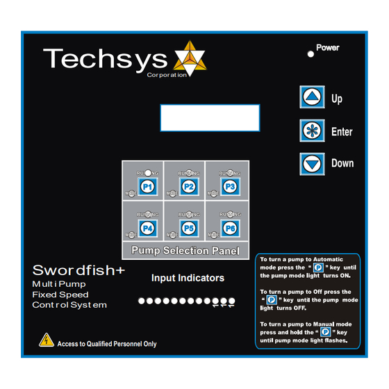
Cut In Level 1 In Delay Out Delay Cut Out Level 3 Cut Out Level 2 Cut Out Level 1 Low Level Alarm or Shut Down www.techsys.com.au Version 1.3 11/12/11 C o r p o r a t io n... - Page 8 Pump Control Panel The interface for SWORDFISH + Control Panel allows access for the operator to edit values throughout the menus. Techsys Two line LCD Cor por at ion Display Pump RUN Indicator (One for each pump) Pump ON/OFF/Manual Switch (Mode)
-
Page 9: Moving Around & Editing Menu Items
To move out of a submenu press the up or down key to scroll to the top or bottom of the submenu and the display will return to the main menu area. www.techsys.com.au Version 1.3 11/12/11 C o r p o r a t io n... - Page 10 Version 1.3 11/12/11 C o r p o r a t io n...
- Page 11 Version 1.3 11/12/11 C o r p o r a t io n...
-
Page 12: Menus
* Hours Run 2-6 are only visible if "Number of pumps" is set accordingly * Pump Start 2-6 are only visible if "Number of pumps" is set accordingly Main Menu Units Defaults Range Access Code number 0 - 250 www.techsys.com.au Version 1.3 11/12/11 C o r p o r a t io n... - Page 13 * OFF is displayed in the "Lo Press Delay" screen when "Low Limit Action" is set to "OFF" * OFF is displayed in the "Hi Press Delay" screen when "HighLimit Action" is set to "OFF" www.techsys.com.au Version 1.3 11/12/11 C o r p o r a t io n...
- Page 14 0 - 999 "JP In Delay Time seconds 0 - 999 * JP Screens are only visible is "Jockey Pump" is set to " ===ON===" www.techsys.com.au Version 1.3 11/12/11 C o r p o r a t io n...
- Page 15 * Pump Run 2 - 6 are only visible if "Number of pumps" is set accordingly * Pump Fault 2 - 6 are only visible if "Number of pumps" is set accordingly www.techsys.com.au Version 1.3 11/12/11 C o r p o r a t io n...
- Page 16 * Pump NoFlowProt 2 - 6 are only visible if "Number of pumps" is set accordingly * Level Cut In 1-6 & Cut Out 1-6 are only visible when operating "Switched" "Multi level" www.techsys.com.au Version 1.3 11/12/11 C o r p o r a t io n...
-
Page 17: System Status
It will also be logged in the FAULT HISTORY menu. There is space for up to 5 faults to be logged which scroll down as new faults are received. www.techsys.com.au Version 1.3 11/12/11 C o r p o r a t io n... - Page 18 To reset the complete FAULT HISTORY by pressing ENTER then DOWN and then ENTER again when at Fault 1. Individual Faults can be reset by completing the same action while displaying the Fault screen to be reset. www.techsys.com.au Version 1.3 11/12/11 C o r p o r a t io n...
-
Page 19: Pump Data Log
1 hour. After the first hour the last 6 previous 10-minute readings are added together to get the Starts last hour reading. To reset press ENTER then DOWN and then ENTER again. www.techsys.com.au Version 1.3 11/12/11 C o r p o r a t io n... - Page 20 Temperature Temperature Displayed is the current temperature in degrees C, XXX degrees C read via the temperature sensor on the circuit board. www.techsys.com.au Version 1.3 11/12/11 C o r p o r a t io n...
-
Page 21: Access Code
If Low Limit Action is set to Shutdown, then a shutdown is initiated. For alarm and shutdown actions, an output relay can be set to the appropriate mode to turn it on. www.techsys.com.au Version 1.3 11/12/11 C o r p o r a t io n... - Page 22 If High Limit Action is set to Alarm, then an alarm is only logged. ➢ If High Limit Action is set to Shutdown, then a shutdown is initiated. www.techsys.com.au Version 1.3 11/12/11 C o r p o r a t io n...
- Page 23 Settings (Alt Cut In 2 - Alt Cut Out 2) • Settings (Alt Cut In 3 - Alt Cut Out 3) Alt Cut Out 3 XXXX www.techsys.com.au Version 1.3 11/12/11 C o r p o r a t io n...
- Page 24 If Alt Cut In & Alt Cut Out 2 or 3 are not used, adjust these settings to be close to the “standard” CUT OUT, this should prevent them from limiting adjustment to the High Level and Low Level settings. www.techsys.com.au Version 1.3 11/12/11 C o r p o r a t io n...
- Page 25 “Trip Point ” within the OUTPUTS menu. Level trip 1 High Level trip 1 Low TIME Relay Energized Relay Off Relay Energized Relay State www.techsys.com.au Version 1.3 11/12/11 C o r p o r a t io n...
-
Page 26: Timing
The In delay timer is used to start every pump apart from the first pump after a restart. This timer is designed to assist in the reduction of Short Cycling and allowing the system to stabilise before additional pumps are started. www.techsys.com.au Version 1.3 11/12/11 C o r p o r a t io n... - Page 27 Note: The screens “Level Trip Low Delay” and “Level Trip High Delay” are only visible if at least one output is set to “Trip point” in the OUTPUTS menu. www.techsys.com.au Version 1.3 11/12/11 C o r p o r a t io n...
- Page 28 Note: The “Min Pump Runtime” and “Max Pumps Starts” screens are visible according to the setting of “Excess Run Prot’n” sub menu in the “Configuration” Menu. www.techsys.com.au Version 1.3 11/12/11 C o r p o r a t io n...
-
Page 29: Configure
Pending selection of the above will cause several settings to be reversed in mode of operation or menu listing i.e. Cut In Level for tank empty now becomes Cut Out Level for tank filling application etc. www.techsys.com.au Version 1.3 11/12/11 C o r p o r a t io n... - Page 30 5 seconds before accepting the adjustment. Note: This screen will not be displayed if the SWORDFISH + is running in switched mode www.techsys.com.au Version 1.3 11/12/11 C o r p o r a t io n...
- Page 31 Note: A forced rotation can be activated by setting one of the programmable inputs to “Cycle Pumps” and closing the relevant input terminals- see Programmable Inputs. www.techsys.com.au Version 1.3 11/12/11 C o r p o r a t io n...
- Page 32 A message will appear on the status screen letting you know that it www.techsys.com.au Version 1.3 11/12/11 C o r p o r a t io n...
- Page 33 To edit press enter and then up or down keys to edit the new number. Press enter again and exit the menu to store the changes. www.techsys.com.au Version 1.3 11/12/11 C o r p o r a t io n...
-
Page 34: Jockey Pump
Given that no main pumps have started. NOTE: IF THE JOCKEY PUMP IS TURNED “ON”, RELAY 4 IS NO LONGER AVAILABLE FOR ANY OTHER FUNCTION. www.techsys.com.au Version 1.3 11/12/11 C o r p o r a t io n... -
Page 35: Outputs
You can view which outputs are currently activated within the PUMP DATA LOG menu, under Digital Output State. The status of the analogue outputs is also available within this menu. www.techsys.com.au Version 1.3 11/12/11 C o r p o r a t io n... - Page 36 A shutdown based on a High Level Shutdown. • Pump 1-6 Run Pump 1-6 running. • Pump 1-6 Shutdown Pump 1-6 shutdown on individual pump protection. www.techsys.com.au Version 1.3 11/12/11 C o r p o r a t io n...
- Page 37 The relays are rated at 5 amp 250VAC. Consideration of inrush current, inductive loads and cycling must be taken into account when applying current to these relays. www.techsys.com.au Version 1.3 11/12/11 C o r p o r a t io n...
- Page 38 You can view which inputs are activated by the leds on the front of the unit and also within the PUMP DATA LOG menu under the “Digital Input State” screens. See PUMP DATA LOG for more information. www.techsys.com.au Version 1.3 11/12/11 C o r p o r a t io n...
-
Page 39: Inputs
No Flow Prot Dly Continuous Pump 6 NoFlowProt No Flow Prot Dly Continuous Not Selected When this is selected the input will not respond to any activation. www.techsys.com.au Version 1.3 11/12/11 C o r p o r a t io n... - Page 40 This protection is ideal for the following pump protection sensors: • Temperature probes • Thermal Overloads • Moisture sensor for oil bath pump seals • Any individual pump protection device. www.techsys.com.au Version 1.3 11/12/11 C o r p o r a t io n...
- Page 41 If pump 1 started first on the last start-up, the toggling of this input will switch the lead pump to pump 2 instantly on receipt of this signal. www.techsys.com.au Version 1.3 11/12/11 C o r p o r a t io n...
- Page 42 Individual Loss of prime pressure switches • Any individual pump protection device. External contacts must be VOLTAGE FREE - any applied voltage can cause damage to the system. www.techsys.com.au Version 1.3 11/12/11 C o r p o r a t io n...
- Page 43 PRESSURE TRANSDUCER INPUT P VOLTS To use this input, note the wiring requirements on the PCB. A regulated 24VDC power supply is available on board for 2-wire configuration. www.techsys.com.au Version 1.3 11/12/11 C o r p o r a t io n...
- Page 44 0-10 V transducers are set up for standard 3-wire operation. INTERNAL TRANSDUCER ANALOGUE INPUTS 24V 24VDC TRANSDUCER SUPPLY PRESSURE TRANSDUCER INPUT P VOLTS www.techsys.com.au Version 1.3 11/12/11 C o r p o r a t io n...
-
Page 45: Pump Protection
This protection is ideal for the following pump protection sensors: • Temperature probes • Loss of prime pressure switches • Thermal Overload • Thermistor ALL FAULTS CAN BE REMOTELY RESET FROM THE “RESET INPUT” www.techsys.com.au Version 1.3 11/12/11 C o r p o r a t io n... -
Page 46: Calibration Of Analogue Sensors
Press the UP key until a “zero” value appears. Once completed press ENTER again and back out of the menu to initiate a store of the “zero” value. www.techsys.com.au Version 1.3 11/12/11 C o r p o r a t io n... - Page 47 With standard transducers you will be able to read level to an accuracy of 4% under normal conditions.. www.techsys.com.au Version 1.3 11/12/11 C o r p o r a t io n...
-
Page 48: Specifications
Standard - AS3000 230 - 440V Input supply Voltage - 3 phase Input supply tolerance - 3 -20% + 10% phase Input frequency range 48 to 62 Hz www.techsys.com.au Version 1.3 11/12/11 C o r p o r a t io n... -
Page 49: Pcb Hardware & Specifications
The figure below shows the terminal configurations for the SWORDFISH +. Detailed above are the locations for the components for the Swordfish+ Printed Circuit Board (PCB) www.techsys.com.au Version 1.3 11/12/11 C o r p o r a t io n... - Page 50 Version 1.3 11/12/11 C o r p o r a t io n...
-
Page 51: Spare Parts
SPARE PARTS The typical spare parts required for SWORDFISH + are detailed in the table below. Please refer to Techsys Corporation for confirmation of parts type and suitability for use with specific projects. Part Code 0-250mV Standard pressure transducer 24P-Trans... -
Page 52: Troubleshooting
• Make sure that the to the Inputs. Inputs are Voltage • Cut In & Cut Out are Free • Adjust Cut In lower or incorrect. Cut Out higher www.techsys.com.au Version 1.3 11/12/11 C o r p o r a t io n... - Page 53 A SOLID light or NO light on either means the SWORDFISH + is inoperative. www.techsys.com.au Version 1.3 11/12/11 C o r p o r a t io n...
-
Page 54: Installation Notes
INSTALLATION NOTES General Installation information can be obtained from Techsys Corporation regarding the site-specific requirements however there are some “GOLDEN RULES” in site installation that should be followed. Site Installation • Standard SWORDFISH + requires a NEUTRAL • Select the site most shaded and out of direct sunlight. -
Page 55: Site Record
Alt Cut In 2 Alt Cut Out 2 Alt Cut In 3 Alt Cut Out 3 Trip Point Low Trip Point High TIMING LoLevel Delay HiLevel Delay www.techsys.com.au Version 1.3 11/12/11 C o r p o r a t io n... - Page 56 JP Cut In Level JP Cut Out Level JP Run On Time JP In Delay Time Digital Output 1 OUTPUTS Digital Output 2 Digital Output 3 Digital Output 4 www.techsys.com.au Version 1.3 11/12/11 C o r p o r a t io n...
- Page 57 Program Input 7 Program Input 8 Program Input 9 Program Input 10 Program Input 11 Program Input 12 Commissioned by……………………………………………..Date…………………… Agent…………………………………………… Contact details………………………………… Panel Serial Number ……………………………………………. www.techsys.com.au Version 1.3 11/12/11 C o r p o r a t io n...
- Page 58 NOTES ……………………………………………………………………………………………… ……………………………………………………………………………………………… ……………………………………………………………………………………………… ……………………………………………………………………………………………… ……………………………………………………………………………………………… ……………………………………………………………………………………………… ……………………………………………………………………………………………… ……………………………………………………………………………………………… ……………………………………………………………………………………………… ……………………………………………………………………………………………… ……………………………………………………………………………………………… ……………………………………………………………………………………………… ……………………………………………………………………………………………… ……………………………………………………………………………………………… ……………………………………………………………………………………………… ……………………………………………………………………………………………… ……………………………………………………………………………………………… ……………………………………………………………………………………………… www.techsys.com.au Version 1.3 11/12/11 C o r p o r a t io n...
- Page 59 Level Trip, 22 Zero Level, 5 High level, 20 Level Trip delay, 24 Hour Run, 17 Level Trip High Delay, 24 How to change data, 8 www.techsys.com.au Version 1.3 11/12/11 C o r p o r a t io n...
- Page 61 C o r p o r a t io n Techsys Corporation Pty Ltd Ph: 03 97065311 Fax 03 97065870 Email: sales@techsys.com.au Website support: www.techsys.com.au...
Need help?
Do you have a question about the SWORDFISH+ and is the answer not in the manual?
Questions and answers