Table of Contents
Advertisement
Owner's Manual & Safety Instructions
Save This Manual
operating, inspection, maintenance and cleaning procedures. Write the product's serial number in the
back of the manual near the assembly diagram (or month and year of purchase if product has no number).
Keep this manual and the receipt in a safe and dry place for future reference.
Email our technical support at: productsupport@harborfreight.com
When unpacking, make sure that the product is intact
and undamaged. If any parts are missing or broken,
please call 1-888-866-5797 as soon as possible.
©
Copyright
2014 by Harbor Freight Tools
No portion of this manual or any artwork contained herein may be reproduced in
any shape or form without the express written consent of Harbor Freight Tools.
Diagrams within this manual may not be drawn proportionally. Due to continuing
improvements, actual product may differ slightly from the product described herein.
Tools required for assembly and service may not be included.
Keep this manual for the safety warnings and precautions, assembly,
Visit our website at: http://www.harborfreight.com
®
. All rights reserved.
Read this material before using this product.
Failure to do so can result in serious injury.
SAVE THIS MANUAL.
17i
Advertisement
Table of Contents

Related Manuals for Pittsburgh Automotive 62325


Summary of Contents for Pittsburgh Automotive 62325
- Page 1 Owner’s Manual & Safety Instructions Save This Manual Keep this manual for the safety warnings and precautions, assembly, operating, inspection, maintenance and cleaning procedures. Write the product’s serial number in the back of the manual near the assembly diagram (or month and year of purchase if product has no number). Keep this manual and the receipt in a safe and dry place for future reference.
-
Page 2: Specifications
The operator must understand that common sense and caution are factors, which cannot be built into this product, but must be supplied by the operator. SAVE THESE INSTRUcTIONS. Page 2 For technical questions, please call 1-888-1-888-866-5797. Item 62325... - Page 3 Secure each Pin with an R-Clip (16). R-clip (16) Upper Ram pin ( 24 ) Ram ( 6 ) Washer ( 30 ) Lower Ram pin ( 15 ) Step 2: Install Ram Item 62325 For technical questions, please call 1-888-1-888-866-5797. Page 3...
- Page 4 Hold Washer (14) over end of Extension Beam Pin and secure it with R-Clip (16). Extension beam pin ( 38 ) Upper Lift Arm (27) Extension beam ( 37 ) Washer ( 14 ) R-clip ( 16 ) Step 4: Attach Extension beam Page 4 For technical questions, please call 1-888-1-888-866-5797. Item 62325...
- Page 5 Replace the Washer over the end of each Wheel Bracket Rod and use an R-Clip to secure the end of each Rod in place. R-clip (16) Washer (34) Wheel bracket Rod (35) Wheel bracket (36) Step 6: Attach Wheel bracket Rods Item 62325 For technical questions, please call 1-888-1-888-866-5797. Page 5...
- Page 6 Step 7: Install Foot pedal 8. Insert the Handle (26) into the bracket on the Lift Arm / S haft Assembly and align the holes. Secure in place using the Handle Bolt (24) and Washer (13). Handle (26) Washer (13) Handle bolt (24) Step 8: Install Handle Page 6 For technical questions, please call 1-888-1-888-866-5797. Item 62325...
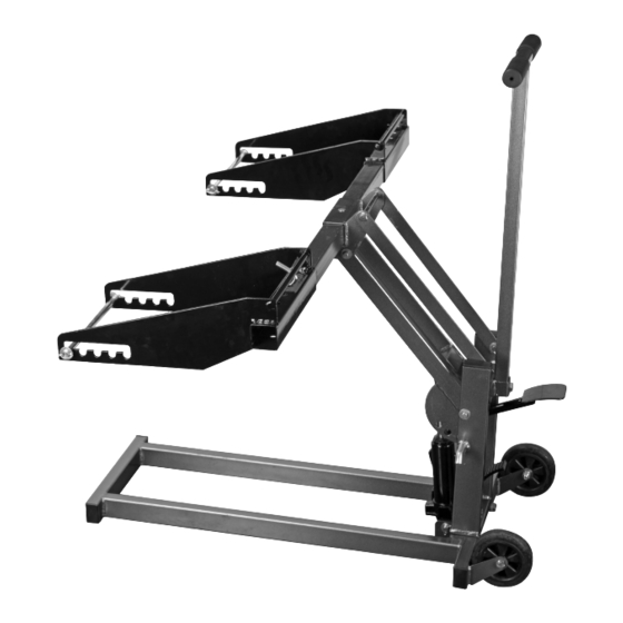
- Page 7 Wheel bracket Width pin D-Ring Foot pedal Safety Lock Lever Fluid Fill Hole Fluid Fill Release pedal plug Safety Lock Levers in Safety Lock Levers in LOcKED position. UNLOcKED position. Item 62325 For technical questions, please call 1-888-1-888-866-5797. Page 7...
- Page 8 5. When not in use, store Lift in a safe, dry 3. Raise the two Safety Lock Levers to the horizontal, location out of reach of children. unlocked position to disengage the locking mechanism. Refer to Components on page 7. Page 8 For technical questions, please call 1-888-1-888-866-5797. Item 62325...
-
Page 9: Maintenance And Servicing
Unit may have too much hydraulic fluid inside. Check fluid level and adjust if needed. Check that the two Safety Lock Levers are in the horizontal, unlocked position to disengage locking mechanism. Item 62325 For technical questions, please call 1-888-1-888-866-5797. Page 9... -
Page 10: Parts List And Diagram
Note: If product has no serial number, record month and year of purchase instead. Note: Some parts are listed and shown for illustration purposes only, and are not available individually as replacement parts. Page 10 For technical questions, please call 1-888-1-888-866-5797. Item 62325... -
Page 11: Assembly Diagram
Assembly Diagram Item 62325 For technical questions, please call 1-888-1-888-866-5797. Page 11... -
Page 12: Limited 90-Day Warranty
Limited 90 Day Warranty Harbor Freight Tools Co. makes every effort to assure that its products meet high quality and durability standards, and warrants to the original purchaser that this product is free from defects in materials and workmanship for the period of 90 days from the date of purchase.
Need help?
Do you have a question about the 62325 and is the answer not in the manual?
Questions and answers
How to replace the safety lock lever
The manual states that all repairs and parts replacements, including the safety lock lever, should be performed by certified and licensed technicians. The manufacturer does not recommend that the buyer replace parts like the safety lock lever themselves.
This answer is automatically generated
It will no longer lift my mower. I have tightened the red covered screw and added fluid and also bleed the jack. any suggestions
To troubleshoot a Pittsburgh Automotive jack (part number 62325) that will not lift a mower, follow these steps:
1. Check the Release Pedal – Ensure it is not stuck and fully raises. A stuck pedal can block valves from closing properly.
2. Flush the Valves – With assistance:
- Lower the Lift Arm and release the Release Pedal.
- Manually lift the Lift Arm several inches.
- Press the Release Pedal and force the Lift Arm down quickly.
3. Check Hydraulic Fluid Level – If the ram is low on fluid, refill it as needed.
4. Bleed the Ram – If the system feels spongy, the ram may need bleeding.
5. Check for Excess Fluid – Too much hydraulic fluid can prevent proper lifting. Adjust fluid level if necessary.
6. Check Safety Lock Levers – Make sure both levers are in the horizontal, unlocked position to disengage the locking mechanism.
This answer is automatically generated