Table of Contents
Advertisement
Quick Links
Advertisement
Table of Contents

Related Manuals for Wahuda 60170ML-WHD

Summary of Contents for Wahuda 60170ML-WHD
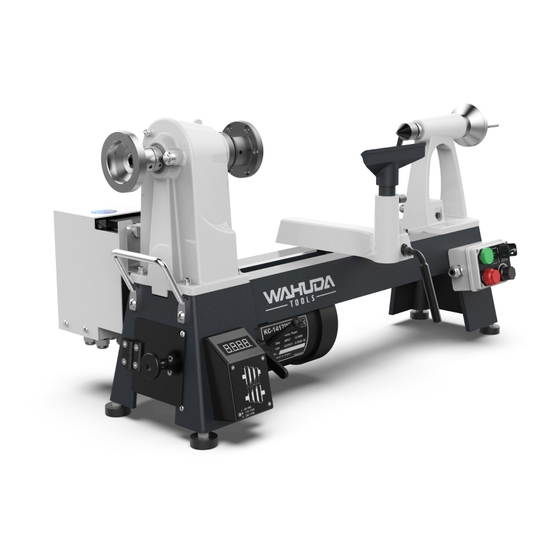
- Page 1 User Manual Read this manual before using machine to avoid serious injury and damage 60170ML-WHD 14” Variable Speed Woodworking Mini Lathe with Wired Remote and Digital Readout For technical support, email or call 877-568-8879 techservices@wahudatools.com VER. 20.03.15...
-
Page 2: Table Of Contents
The drawings, illustrations, photographs, and specifications in this user manual represent your machine at time of print. However, changes may be made to your machine or this manual at any time with no obligation to WAHUDA. -
Page 3: Warranty
2 YEAR LIMITED WARRANTY WAHUDA warrants its machinery to be free of defects in workmanship and materials for a period of two (2) years from the date of the original purchase by the original owner. This warranty applies to products sold in United States only. The warranty does not apply to any product used for professional or commercial production purposes nor for industrial or educational applications. -
Page 4: Product Specifications
PRODUCT SPECIFICATIONS Motor power input 120 V, 60 Hz, 1PH, AC, 13 Amp Motor (VFD inverter controlled) 230V, 60HZ, 3 PH, 1 HP, AC, 3 Amp, 1720 RPM Lathe RPM 0 - 800 / 0 - 1750 / 0 - 3600 Headstock Spindle Taper Drive Spindle Thread 1 ¼”... - Page 5 FEATURE IDENTIFICATION (cont.) WIRED REMOTE CONTROL WITH MAGNETIC BACK...
-
Page 6: General Safety
GENERAL SAFETY NOTE: The WARNING! and CAUTION! symbols indicate a potentially hazardous situation which, if not avoided, COULD result in death or serious injury. READ THIS MANUAL completely before assembling and operating this machine. WARNING! TO AVOID serious injury, death, or damage to the machine, please read, understand, and follow, all Safety and Operating Instructions before assembling and operating this machine. - Page 7 GENERAL SAFETY (cont.) ALWAYS keep the work area clean, well lit, and organized. DO NOT work in an area that has slippery floor surfaces from debris, grease, and wax. CAUTION! ALWAYS unplug the machine from the electrical receptacle when making adjustments, changing parts or performing any maintenance.
- Page 8 GENERAL SAFETY (cont.) KEEP protective guards in place and in working order. CAUTION! MAINTAIN your balance. DO NOT extend yourself over the tool. Wear oil resistant rubber soled shoes. Keep floor clear of debris, grease, and wax. MAINTAIN all machines with care. ALWAYS KEEP machine clean and in good working order. KEEP all blades and tool bits sharp.
-
Page 9: Product Safety
WARNING! DO NOT handle the plug or machine with wet hands USE only accessories as described in this manual and recommended by WAHUDA. 10. DO NOT pull the jointer by the power cord. NEVER allow the power cord to come in contact with sharp edges, hot surfaces, oil or grease. - Page 10 PRODUCT SAFETY (cont.) 16. INSPECT all stock before beginning operations ensuring that there are no foreign objects embedded in the wood, loose knots, or knots that may become loose during operation. WARNING! DO NOT attempt to remove jams until power is disconnected and all moving parts have come to a complete stop.
-
Page 11: Grounding Instructions
GROUNDING INSTRUCTIONS WARNING! This machine MUST BE GROUNDED while in use to protect the operator from electric shock. In the event of a malfunction or breakdown, GROUNDING provides the path of least resistance for electric current and reduces the risk of electric shock. The plug MUST be plugged into a matching electrical receptacle that is properly installed and grounded in accordance with ALL local codes and ordinances. - Page 12 GROUNDING INSTRUCTIONS (cont.) Make certain the extension cord is properly sized, and in good electrical condition. Always replace a worn or damaged extension cord immediately or have it repaired by a qualified person before using it. Protect your extension cords from sharp objects, excessive heat, and damp or wet areas. MINIMUM RECOMMENDED GAUGE FOR EXTENSION CORDS (AWG) 115 VOLT OPERATION ONLY 25’...
-
Page 13: Unpacking & Inventory
Compare the items to inventory figures and verify that all items are accounted for. If any parts are missing, do not attempt to power on the machine. For missing parts, or shipping damage, contact WAHUDA at techservices@wahudatools.com or call 877-568-8879. -
Page 14: Assembly & Adjustments
ASSEMBLY & ADJUSTMENTS WARNING! MAKE CERTAIN THAT THE MACHINE IS DISCONNECTED FROM THE POWER SOURCE BEFORE ASSEMBLY AND ADJUSTMENTS NOTE: 95% of the machine comes fully assembled. If you need help assembling the remaining 5%, use the parts diagram and parts list at the back of this manual for assistance. - Page 15 ASSEMBLY & ADJUSTMENTS (cont.) FASTENING LATHE TO SUPPORTING SURFACE If during operation there is any tendency for the lathe to tip over, slide, or walk on the supporting surface, the base of the lathe must be secured to the supporting surface with fasteners (not supplied) through the four threaded holes (3/8"x16 UNC) located in the feet of the lathe bed.
-
Page 16: Operations
OPERATIONS NOTE: This operations section was designed to give instructions on the basic operations of this lathe. It is strongly recommended that you read books, trade magazines, or get formal training to maximize the potential of your lathe while minimizing the risks. ADJUSTING THE TOOL REST The tool rest should be positioned as close as possible to the workpiece. - Page 17 OPERATIONS (cont.) CHANGING BELT SPEEDS WARNING! MAKE CERTAIN THAT THE MACHINE IS DISCONNECTED FROM THE POWER SOURCE. NOTE: The lowest speed pulley combination is furthest from the faceplate, i.e. smallest motor pulley diameter to largest spindle pulley diameter. 1) Open the access panel (A) on the headstock by loosening the access panel lock screw (B) SEE FIG 6 &...
- Page 18 OPERATIONS (cont.) WARNING! MAKE CERTAIN THAT THE MACHINE IS DISCONNECTED FROM THE POWER SOURCE. 3) Loosen the motor clamping handle (A) and lift the motor handle (B) to loosen belt tension and allow the belt to be moved to another pulley. SEE FIG 10 4) Move the belt to the desired pulley positions on both the motor and headstock pulleys.
- Page 19 OPERATIONS (cont.) WARNING! MAKE CERTAIN THAT THE MACHINE IS DISCONNECTED FROM THE POWER SOURCE. REMOVING AND INSTALLING THE DRIVE CENTER 1) To remove the drive center (A) locate the push rod (B) While holding the drive center, insert the push rod through the center hole of the headstock wheel (C) and push the drive center out.
- Page 20 OPERATIONS (cont.) WARNING! MAKE CERTAIN THAT THE MACHINE IS DISCONNECTED FROM THE POWER SOURCE. REMOVING AND INSTALLING THE HEADSTOCK FACEPLATE 1) With the drive center already removed, (See instructions previous page) rotate the faceplate (A) until the machined hole in the shaft, as seen through the access hole (B) in the spindle collar lines up with the spindle collar (C).
- Page 21 OPERATIONS (cont.) WARNING! MAKE CERTAIN THAT THE MACHINE IS DISCONNECTED FROM THE POWER SOURCE. INDEXING OPERATION The indexing operation is useful for fluted columns, clock faces, and accurate hole positioning. The index pulley has 24 positions (15 degree) , when using the supplied magnetic index pin (See page 13 item D) 1) Open the access panel (FIG 6 &...
-
Page 22: Maintenance
MAINTENANCE WARNING! MAKE CERTAIN THAT THE MACHINE IS DISCONNECTED FROM THE POWER SOURCE BEFORE PERFORMING ANY MAINTENANCE PROCEDURES DAILY AFTER USE Clean shavings away from the lathe bed and tool rest, etc. MONTHLY Check the belt tension and adjust if necessary. See pages 17 and 18 for instructions. Check for any build-up of wood shavings on the motor and pulleys and clean if necessary Using compressed air, lightly blow out the motor vents. -
Page 23: Troubleshooting
TROUBLESHOOTING GUIDE PROBLEM LIKELY CAUSE SOLUTION Motor will not start. Not plugged in. Check the power source. Blown circuit. Replace fuse, reset breaker, or call Improper Voltage. electrician. Unit not turned on. Switch unit on. Belt too tight Adjust belt tension Fuses or circuit Short circuit in line cord or plug. -
Page 24: Parts Diagram & Lists
PARTS... - Page 25 PARTS (cont.)
- Page 26 PART NO. DESCRIPTION SPECIFICATION Q'ty 60170-1 Face plate 3" 60170-2 Spur Center 60170-3 5*5*25 60170-4 Spindle 1-1/4"-8UNC 60170-5 Set Screw 1/4"x1/4" 60170-6 Spindle Pulley 3 SPEED 60170-7 Bearing 6005VV 60170-8 Set Screw M3x16mm 60170-9 60170-10 Set Screw M10x20 60170-11 Lock Pin 60170-12B Cover 60170-13...
- Page 27 60170-32 Locking Handle 5/16"X20MM 60170-33 Clamping Shaft 60170-34 Bushing 60170-35 C-Ring S-14 60170-36 Clamp bolt 60170-37 Clamp 60170-37A Clamp 60170-38 M10*1.5P 60170-38A 60170-39 Shaft 60170-40 Motor 3/4HP 60170-41B Motor Label 60170-42 Locking Handle 60170-43 Hex head Screw 5/16"x1-1/4" 60170-44 Washer 5/16"-3mm 60170-45 Washer...
- Page 28 60170-64B Locking Nut 60170-65 1/4" 60170-66 Set screw 3/16"x1/4" 60170-67 Round Head Screw 1/4"-20x5/8" 60170-68 Set screw 1/4-20*3/8 60170-69 Inverter M-Type (110V) 60170-70 Round Head Screw #10-24-3/4" 60170-71 Nylon Nut 3/16" 60170-72B Inverter board 60170-75 Junction box 60170-76 Strain relief 60170-76-1 cord protector PG11...
- Page 29 60170-80-14 wire 3 60170-81 Control wire 60170-84 Tapping Screw M3x14MM 60170-85 Warning Label 60170-86 Round Head Screw M4x6MM 60170-87 Washer 60170-88 Nylon Nut 60170-90 Round Head Screw M3x30 60170-92 Speed Label 60170-93B Warning label 60170-93B1 Warning label 60170-95 Motor wire 60170-96 Round head screw #10-24X3/4"...
- Page 30 60170-116 Cord Snap Ring ACC-2.5 60170-117 Tapping Screw M3x8 60170-118 Inverter cover 60170-119 Round Head Screw #10-24UNC*1/4"...
- Page 31 WIRING DIAGRAM...
Need help?
Do you have a question about the 60170ML-WHD and is the answer not in the manual?
Questions and answers