Table of Contents
Advertisement
Advertisement
Table of Contents

Related Manuals for International Biomedical Airborne Voyager


Summary of Contents for International Biomedical Airborne Voyager
- Page 1 ® Voyager Transport Incubator Service Manual...
- Page 2 Voyag nfant Tran nspo rt Inc cuba ator S Syste with Opti ional l Pul lseOx Servi ice M Manua hone: (51 12) 873-00 ax: (512) 873-9090 Mail: les@int-b bio.com ebsite: h http://www w.int-bio. .com ailing add dress: ternation...
-
Page 3: Table Of Contents
TABLE OF CONTENTS LANGUAGE DISCLAIMER ........................4 SECTION 1: GENERAL INFORMATION ................... 11 INTRODUCTION ........................11 CLASSIFICATION ........................12 SAFETY SUMMARY ......................... 12 IMPORTANT SAFETY CONSIDERATIONS ................12 SYMBOLS ..........................18 SECTION 2: SET-UP INSTRUCTIONS ....................19 UNPACKING AND ASSEMBLY OF INCUBATOR AND CART .......... - Page 4 TABLE OF CONTENTS OPERATIONAL ALARMS AND WARNINGS ................50 TEST OF OPERATIONAL ALARMS ..................50 OXYGEN SENSOR ........................51 SECTION 6: PREVENTATIVE MAINTENANCE ................52 DAILY MAINTENANCE ......................52 OPERATIONAL CHECK ....................52 AIR / OXYGEN SYSTEM ....................53 ...
- Page 5 TABLE OF CONTENTS ALARMS ........................76 POWER FAIL ALARM ....................77 VOLTAGE REFERENCE ....................77 LAMP DRIVE CIRCUIT ....................77 BATTERY CHARGER ....................78 POWER SOURCE SELECTION..................79 DISPLAY BOARD ........................79 MEASURED TEMPERATURE DISPLAY ............... 79 ...
-
Page 6: Language Disclaimer
LA ANGUAG G E DIS SCLAIM M ER Par rt No. 715-008 8 4, Rev. A - 4 -... - Page 7 LA ANGUAG G E DIS SCLAIM M ER Par rt No. 715-008 8 4, Rev. A - 5 -...
- Page 8 LA ANGUAG G E DIS SCLAIM M ER Par rt No. 715-008 8 4, Rev. A - 6 -...
- Page 9 LA ANGUAG G E DIS SCLAIM M ER Par rt No. 715-008 8 4, Rev. A - 7 -...
- Page 10 LA ANGUAG G E DIS SCLAIM M ER Par rt No. 715-008 8 4, Rev. A - 8 -...
- Page 11 LA ANGUAG G E DIS SCLAIM M ER Par rt No. 715-008 8 4, Rev. A - 9 -...
- Page 12 LA A NGUAG G E DIS SCLAIM M ER Par rt No. 715-008 8 4, Rev. A - 10 -...
-
Page 13: Section 1: General Information
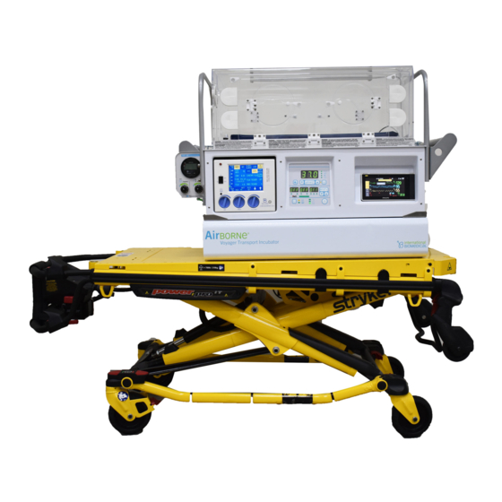
The transport incubator is also intended to carry equipment designed for airway management and monitoring of the neonatal infant's status. The International Biomedical Voyager Infant Transport Incubator with optional PulseOx (referred to herein as the incubator) provides a thermally regulated environment to support an infant’s temperature requirements and has the capability to monitor vital information during transport. -
Page 14: Classification
All personnel operating the incubator must be familiar with the warnings and operating procedures contained in this manual. International Biomedical is not to be held responsible if the incubator is used in a manner inconsistent with the instructions herein. - Page 15 Use of accessories, transducers, and cables other than those specified, with the exception of cables and transducers sold by International Biomedical, may result in increased emissions or decreased immunity of the incubator. The transport incubator contains a sealed lead battery and must be recycled or disposed of properly.
- Page 16 This incubator was calibrated with the infant chamber originally supplied. If this chamber is exchanged for an infant chamber of a different configuration or size, the temperature calibration will be affected. Consult International Biomedical before returning the incubator to service. ...
- Page 17 Connecting equipment to the outlets on this device creates a medical electrical system and the user is responsible for continued compliance with the requirements of IEC 60601-1. Do not modify this equipment without proper authorization from International Biomedical. An Infant Transport Incubator should be used by appropriately trained personnel and under the direction of qualified medical staff familiar with currently known risks and benefits of Infant Transport Incubator use.
- Page 18 Use only parts, accessories, transducers, and cables designated by International Biomedical for use with the transport incubator. Cables and accessories other than those supplied by International Biomedical may result in unacceptable operation of the transport incubator and will void the equipment warranty.
- Page 19 SECTION 1: GENERAL INFORMATION should be disposed of properly, or returned to Maxtec or International Biomedical for proper disposal or recovery. Pulse oximeter probes and cables are designed for use with specific monitors. Only use Masimo sensors and patient cables for Masimo pulse oximetry model. Only use Nellcor sensors and patient cables for Nellcor pulse oximetry model.
-
Page 20: Symbols
ECTION N 1: GE ENERA AL INFO ORMAT TION YMBOL he following g symbols a appear in th he incubator r document tation and l abels. The ese internat tionally cognized sy ymbols are defined by y the Interna ational Elec ctrotechnica al Commiss sion, IEC 4... -
Page 21: Unpacking And Assembly Of Incubator And Cart
ECTION N 2: SE ET-UP I INSTRU UCTION NPACK KING A ND ASS SEMBL LY OF IN NCUBA ATOR A AND CA he Voyager Incubator (see Figure e 2 - 1) typic cally ships in 4 separa ate boxes. Upon arriva al, inspect oxes for any y damage. - Page 22 ECTION N 2: SE ET-UP I INSTRU UCTION Use th he draw latc ches on all f four corner rs of the acc cessory mo odule to sec cure the ac ccessory module e to the car Find th he infant po ositioning st traps, usua lly shipped...
-
Page 23: Assembly Of The Ventilation System
ECTION N 2: SE ET-UP I INSTRU UCTION ASSEMB BLY OF F THE V VENTILA ATION S SYSTE he assembly y instructio ns are for t he MVP-10 0 or Crossv vent configu urations, bu t most of th he assembl ocess is als so applicab ble to other... -
Page 24: Section 2: Set-Up Instructions
SECTION 2: SET-UP INSTRUCTIONS ASSEMBLY OF THE HANDLES Locate the two high rise handles and the two standard handles. These handles are usually stored in the accessories box or the air/oxy cart box. Unscrew the nuts on the four bolts located on both ends of the main module. Slide the high rise handle (large inverted U-shape) on first and then the standard handle. -
Page 25: Section 3: Operating Instructions
SECTION 3: OPERATING INSTRUCTIONS This section contains operating procedures for the incubator. The incubator should be operated with external power whenever possible. The incubator’s battery should be fully charged prior to use by connecting the unit to an AC power supply for at least 8 hours. When not in use, the incubator should be plugged into an AC power source in order to recharge the battery. - Page 26 ECTION N 3: OP PERAT TING IN STRUC CTIONS Figure 3 - 1 1 Front Di splay Pane 1. Syste em Fail Alarm Indicator (SYS S FAIL) 2. Sens sor Fail Alarm I Indicator (SEN NS FAIL) 3. Air T Temperature Se etpoint >37...
- Page 27 SECTION 3: OPERATING INSTRUCTIONS 1: System Fail Alarm Indicator (SYS FAIL) Yellow LED indicator that illuminates when the displayed temperature exceeds 39.0 C 2: Sensor Fail Alarm Indicator (SENS FAIL) Yellow LED indicator that illuminates when the temperature being sensed by the primary temperature sensor is outside the normal temperature range of the incubator (10 - 45...
- Page 28 SECTION 3: OPERATING INSTRUCTIONS 12: Battery Life Display Indicator Indicator is illuminated when the Battery Life Display button is pressed and held. 13: Baby Temperature Button (BABY TEMP) When button is pressed, the Main Display Screen will display the temperature measured by the baby temperature probe.
- Page 29 SECTION 3: OPERATING INSTRUCTIONS 23: Oxygen Setpoint Low Indicator (Optional Feature) Indicator is illuminated when the oxygen concentration lower alarm limit is set to a value below 21%. 24: PulseOx SET Button (Optional Feature) Button used to enter modes to set pulse oximetry and oxygen monitor alarm limits and to calibrate the oxygen sensor 25: PulseOx Up and Down Arrows (Optional Feature) Buttons used to set pulse oximetry and oxygen monitoring variables...
-
Page 30: Back Panel Features
ECTION N 3: OP PERAT TING IN STRUC CTIONS BACK PA ANEL F FEATUR he back pan nel of the in ncubator is w where pow wer cords co onnect and where circ uit breakers s are locate gure 3 - 2 s shows a dra awing of the e back pane... -
Page 31: Side Panel Features
ECTION N 3: OP PERAT TING IN STRUC CTIONS Fuse his replacea able 15 A fu use is a sec condary tran nsformer fu use. 3 A Acces ssory Circu uit Breaker hese 3 Amp p circuit bre akers are c connected t to the acces ssory powe... -
Page 32: Power Features
SECTION 3: OPERATING INSTRUCTIONS Pulse Oximeter Sensor Connector (Optional Feature) The SpO and pulse rate sensor used with the Masimo or Nellcor pulse-oximeter connects to this connection point. Refer to SECTION 4 for details on the pulse oximeter system. Baby Temperature Cable Connector The Baby Temperature Cable connects to this connection point. - Page 33 SECTION 3: OPERATING INSTRUCTIONS Battery Power Mode Battery power will automatically be selected when neither AC power nor DC power are available. When operating on internal battery, the BAT OP indicator (Figure 3 - 1, item 31) will be illuminated. Connecting AC or DC power will supersede battery power operation.
-
Page 34: Powering Up The Incubator
SECTION 3: OPERATING INSTRUCTIONS POWERING UP THE INCUBATOR To turn the incubator on, press the Power Button (Figure 3 - 1, item 32) on the lower right hand corner of the Front Display Panel. When the incubator is turned on, all functional LEDs on the display panel will illuminate and the audible alarm will sound. -
Page 35: Temperature Control
SECTION 3: OPERATING INSTRUCTIONS TEMPERATURE CONTROL The infant chamber air temperature can be controlled from the front display panel on the incubator. When the Set Air Temperature Button (Figure 3 - 1, item 15) is pressed, the user can use the up and down arrows (Figure 3 - 1, items 14 &... -
Page 36: Alarms / Indicators
SECTION 3: OPERATING INSTRUCTIONS ALARMS / INDICATORS The incubator utilizes a visual and audible alarm system. Audible alarms can be silenced for approximately one minute using the MUTE button (Figure 3 - 1, item 17). The audible alarm will sound at 65 dB at a distance of 3 m from the operator interface of the incubator. - Page 37 SECTION 3: OPERATING INSTRUCTIONS Power Alarms When the incubator becomes disconnected from AC power, the AC Fail indicator (Figure 3 - 1, item 6) illuminates and an audible alarm will sound. When the incubator becomes disconnected from both AC and DC power and the internal battery voltage falls below 10.1 volts, the PWR FAIL indicator (Figure 3 - 1, item 7) illuminates and a continuous audible alarm sounds.
- Page 38 SECTION 3: OPERATING INSTRUCTIONS If the primary temperature sensor is shorted or indicates an extremely high temperature, the SENS FAIL, HIGH TEMP, and SYS FAIL indicators and alarms will all be activated and the incubator’s heater will be disabled. If the primary temperature sensor is open or indicates an extremely low temperature, the SENS FAIL and SYS FAIL alarms will be activated, and the heater will be disabled.
-
Page 39: External Lighting
SECTION 3: OPERATING INSTRUCTIONS EXTERNAL LIGHTING The incubator is equipped with an external examination light. This light can be activated only when the incubator is turned on. The light is intended to be used as an external light source. Do not place the light into the inner infant chamber. -
Page 40: Section 4: Pulse Oximetry (Optional Feature)
SECTION 4: PULSE OXIMETRY (OPTIONAL FEATURE) This section contains information regarding the pulse oximetry feature of the incubator. Principles of operation, set-up instructions, and sensor options are detailed. PULSE OXIMETER PRINCIPLES OF OPERATION Pulse oximetry is based on several key principles: ... - Page 41 SECTION 4: PULSE OXIMETRY (OPTIONAL FEATURE) Erroneous SpO readings may be caused by several reasons including, but not limited to, the following: Interfering substances such as Carboxyhemoglobin and Methemoglobin (i.e. an increase in approximately equal to the amount of carboxyhemoglobin present) ...
-
Page 42: Pulse Oximeter Set-Up Instructions
SECTION 4: PULSE OXIMETRY (OPTIONAL FEATURE) PULSE OXIMETER SET-UP INSTRUCTIONS The following steps will instruct the user how to initially set up the pulse oximeter and program low and high alarm settings for SpO and pulse rate. Additionally, when using the Masimo pulse oximeter, the user can also set the algorithm mode, set the averaging mode, and view the oxygen perfusion index. -
Page 43: Setting High And Low Pulse Rate Alarms
SECTION 4: PULSE OXIMETRY (OPTIONAL FEATURE) SETTING HIGH AND LOW PULSE RATE ALARMS NOTE: The pulse oximeter display will convert back to Normal Operation Mode after 5 seconds if no buttons are pressed. Press the SET button (Figure 3 - 1, item 24) five times (or until the PULSE HI LED illuminates) to set the high Pulse alarm. -
Page 44: Setting The Averaging Mode (Masimo Only)
SECTION 4: PULSE OXIMETRY (OPTIONAL FEATURE) A2 = Maximum Mode Interprets and displays data for very weak signals. This mode is recommended for the sickest patients or during procedures when clinician and patient contact is continuous. A3 = APOD Mode Least sensitive in picking up a reading on patients with low perfusion but provides the best detection for probe-off conditions. -
Page 45: Setting The Perfusion Index (Masimo Only)
SECTION 4: PULSE OXIMETRY (OPTIONAL FEATURE) SETTING THE PERFUSION INDEX (MASIMO ONLY) The Perfusion Index value represents a ratio between the pulse signal and noise. It helps clinicians determine if the pulse oximetry sensor is placed on an optimal monitoring site. The Perfusion Index value has a range of 0.0 - 20.0 (i.e. - Page 46 SECTION 4: PULSE OXIMETRY (OPTIONAL FEATURE) Low Perfusion (Masimo Only) The system displays “LP” when there are very low amplitude arterial pulsations. It has been suggested that at extremely low perfusion levels, pulse oximeters can measure peripheral saturation, which may differ from central arterial saturation .
-
Page 47: Test Of Operational Alarms
SECTION 4: PULSE OXIMETRY (OPTIONAL FEATURE) TEST OF OPERATIONAL ALARMS To ensure the pulse oximeter is generating the proper alarm indications, the following instructions should be followed: After the sensor is attached to the patient, verify the patient alarms are functional by setting the and pulse rate high and low alarm limits beyond the patient readings. -
Page 48: Pulse Oximetry Testers / Simulators
SECTION 4: PULSE OXIMETRY (OPTIONAL FEATURE) CAUTION: Pulse oximeter probes and cables are designed for use with specific monitors. Only use Masimo sensors and patient cables for Masimo pulse oximetry model. Only use Nellcor sensors and patient cables for Nellcor pulse oximetry model. Verify the compatibility of the monitor, sensor, and cable before use, otherwise patient injury can result. -
Page 49: Section 5: Oxygen Monitor (Optional Feature)
< 95% relative humidity and placed upstream of any humidifier (if used in a breathing circuit) to reduce the risk of water condensation. CAUTION: Only use International Biomedical cable and Maxtec sensor for oxygen monitoring. CAUTION: Use the oxygen monitor when oxygen is delivered to the infant. -
Page 50: Oxygen Monitor Set-Up Instructions
SECTION 5: OXYGEN MONITOR (OPTIONAL FEATURE) OXYGEN MONITOR SET-UP INSTRUCTIONS The following steps will instruct the user how to initially set up the oxygen monitor, program low and high alarm settings, and how to calibrate the oxygen sensor. CAUTION: Check alarm limits each time the system is used to ensure that they are appropriate for the patient being monitored. -
Page 51: Oxygen Monitor Calibration
SECTION 5: OXYGEN MONITOR (OPTIONAL FEATURE) Press the SET button eight times (or until the OXYGEN LO LED illuminates) to set the low Oxygen alarm. Use the up or down arrow buttons to set the low alarm to the desired setting. Must be at least 1% lower than the high oxygen alarm setting. -
Page 52: Operational Alarms And Warnings
SECTION 5: OXYGEN MONITOR (OPTIONAL FEATURE) For oxygen readings to be accurate, the oxygen monitor must be thermally stable when calibrated and when measurements are taken. Calibration should also be done at the same pressure as when in use due to the fact that the flow rate of sample gas can change the back pressure at the sensing point, changing the oxygen reading. -
Page 53: Oxygen Sensor
KOH-type sensors in applications where these gases are present. Use only Maxtec Max-250E oxygen sensors and International Biomedical supplied cables with the incubator. Max-250E oxygen sensors offer quick response, stability, and life greater than 9000 hours. -
Page 54: Section 6: Preventative Maintenance
SECTION 6: PREVENTATIVE MAINTENANCE To ensure proper operation, standby readiness, and malfunction reporting, International Biomedical recommends following a preventative maintenance program. The daily preventative maintenance procedures can be performed by a knowledgeable incubator transport person. Monthly maintenance procedures should be performed by an appropriately trained biomedical maintenance person. No other preventative maintenance is required. -
Page 55: Air / Oxygen System
SECTION 6: PREVENTATIVE MAINTENANCE Disconnect the AC power connection from the incubator and observe that the BAT OP indicator (Figure 3 - 1, item 31) is illuminated and that the Main Display Screen still displays the infant chamber air temperature. Turn on the external light and ensure it operates under Battery power. -
Page 56: Infant Chamber Check
This incubator was calibrated with the infant chamber originally supplied. If this chamber is exchanged for an infant chamber of a different configuration or size, the temperature calibration will be affected. Consult International Biomedical before returning the incubator to service. CART AND ACCESSORIES Inspect the casters for wear or damage. -
Page 57: Cleaning Of Incubator And Chamber
SECTION 6: PREVENTATIVE MAINTENANCE CLEANING OF INCUBATOR AND CHAMBER WARNING: The incubator should be turned off and AC or DC power disconnected when cleaning. CAUTION: CLEANING AND CARE: Do not autoclave, pressure sterilize, or gas sterilize the incubator, cables, or sensors. Use cleaning solutions sparingly as excessive solution can flow into the incubator and cause damage to internal components. -
Page 58: Monthly Maintenance
SECTION 6: PREVENTATIVE MAINTENANCE MONTHLY MAINTENANCE The following procedures should be performed monthly by a biomedical maintenance person. These checks should be in addition to the daily maintenance checks. OPERATIONAL CHECK Connect the incubator to an AC power source and turn the incubator power button on. Adjust the setpoint to 38.9... -
Page 59: Infant Chamber Inspection & Cleaning
SECTION 6: PREVENTATIVE MAINTENANCE Inspect tanks for abrasion, cuts, or other damage. The tanks should be replaced according to the manufacturer’s recommendation. INFANT CHAMBER INSPECTION & CLEANING Carefully inspect the infant chamber for cracks and crazing of the Plexiglas. Check all screws and knobs for tightness. CAUTION: Do not overtighten the infant chamber screws! Wash chamber with mild soap or detergent and water solution to clean the Plexiglas. -
Page 60: Air Flow System Inspection & Cleaning
SECTION 6: PREVENTATIVE MAINTENANCE After stabilization, disconnect the AC power and note the time. The incubator will automatically switch to battery operation. Note the time at which the low battery alarm activates. The difference between the noted times in steps 4 and 5 is the operational time. If this time is less than 1 ¼... -
Page 61: Battery Care
PRODUCT DISPOSAL / RECYCLING The incubator should be returned to International Biomedical for recycling when it reaches the end of its life (7 to 10 years). The incubator’s battery can be taken to any battery recycling facility when it reaches the end of its life (approximately 200 discharge cycles, dependent on depth of discharge). -
Page 62: Section 7: Troubleshooting
Ensure the incubator is turned on; the light gets its power from the incubator and will not work unless the incubator is on. If the light still doesn’t work with the incubator on, it needs to be replaced (e.g. an LED may be bad, there may be a short in the circuitry). Contact International Biomedical for assistance. -
Page 63: Main Display Error Codes
SECTION 7: TROUBLESHOOTING MAIN DISPLAY ERROR CODES Table 7 - 1 shows the failure codes that may be seen on the Main Display Screen. If further assistance is needed, contact International Biomedical. Table 7 - 1 Main Display Screen Failure Codes... - Page 64 SECTION 7: TROUBLESHOOTING Table 7 - 2 Masimo Pulse Oximetry and Oxygen Monitoring Failure Codes %SPO2 PULSE OXYGEN Failure Corrective Action Display Display Display Ensure proper sensor Pulse Search application. Reposition sensor, if (flashing) necessary. Move sensor to better perfused Low Perfusion (flashing) site.
- Page 65 Oximeter. In Table 7 - 3, the error code listed will be displayed on the PULSE display screen. Additional error codes may be displayed on the %SPO2 display screen, but are unnecessary to describe here. If further assistance is needed, contact International Biomedical. Table 7 - 3...
-
Page 66: Section 8: Internal Component Access
SECTION 8: INTERNAL COMPONENT ACCESS This section contains procedures for accessing and removing components from the incubator chassis. WARNING: SERVICE ONLY BY QUALIFIED PERSONNEL: The incubator should be serviced only by qualified personnel in the Electronics Maintenance or Biomedical Engineering Department within the hospital or by International Biomedical personnel. -
Page 67: Battery Removal
The battery can now be carefully removed. CAUTION: Replace battery only with International Biomedical part number 888-0071. CONTROL BOARD REMOVAL This section details the procedure to be followed to remove the control board assembly. The procedure detailed to gain access to the electronics compartment must be followed before beginning this procedure. -
Page 68: Display Board Removal
SECTION 8: INTERNAL COMPONENT ACCESS Remove the six screws securing the printed circuit board to the six standoffs. The control board can now be lifted out of the frame. NOTE: Accessory devices (e.g. ECG Monitor) may need to be removed in order to access the control board hardware. -
Page 69: Pulse Oximeter Board Removal (Optional Feature)
SECTION 8: INTERNAL COMPONENT ACCESS PULSE OXIMETER BOARD REMOVAL (OPTIONAL FEATURE) This section details the procedure to be followed to remove the PulseOx daughter board assembly. The electronics compartment access procedure and steps 1 - 6 of the Display Board Removal procedure must be followed before beginning this procedure. -
Page 70: Section 9: Calibration Procedures
3 Clip lead jumpers (preferably one red and two black) 10 k resistor Airborne temperature test circuit P/N 387-1190 (Available from International Biomedical) Airborne sensor simulator P/N 387-1191 (Available from International Biomedical) Calibrated digital temperature measuring device 0.1 C accuracy... - Page 71 SECTION 9: CALIBRATION PROCEDURES Turn the power button on and observe for a couple of seconds; all LEDs should be illuminated, all seven-segmented LED elements turned on, and the audible alarm on. The BAT CHG and AC OP indicators should stay on. Remove the sensor simulator.
- Page 72 SECTION 9: CALIBRATION PROCEDURES Reconnect the incubator to an appropriate source of AC power and turn the unit on. Adjust the setpoint temperature to 37.0 C. Operate the unit until the temperature inside the infant chamber stabilizes (approximately 30 minutes). If the temperature indicated by the monitoring instrument is not 37.0 ...
-
Page 73: Control Board Calibration Procedure
SECTION 9: CALIBRATION PROCEDURES Connect an external source of 12V DC power to the external 12V DC connector. The DC OP indicator should illuminate. Verify temperature is maintained while powered from external DC for five minutes. Disconnect the external power supply and turn the unit off. CONTROL BOARD CALIBRATION PROCEDURE The following procedure should be used to calibrate the control board with it installed in the transport incubator, after any repairs, prior to system calibration. - Page 74 SECTION 9: CALIBRATION PROCEDURES To check the two independent voltage references, measure the voltage at TP4 and TP10. The voltage should be 5.000 0.005 volts. If necessary, adjust R4 and R10 respectively. To check the calibration of the setpoint temperature circuit, adjust the setpoint temperature to 37.0...
- Page 75 SECTION 9: CALIBRATION PROCEDURES Adjust the voltage of the DC supply to 18.30 0.05 volts. Connect a jumper across R59. (R59 is located 1.5 inches below variable resistor R7.) Set the decade box to 1576 . Turn the incubator power switch on. Observe the waveform at TP12 with an oscilloscope. The duty cycle of the square wave should be 60 ...
-
Page 76: Display Board Calibration Procedure
SECTION 9: CALIBRATION PROCEDURES DISPLAY BOARD CALIBRATION PROCEDURE The following procedure should be used to calibrate the display board. It should be performed once installed in the incubator, after any repairs, and prior to system calibration. CAUTION: The incubator electronics contain static sensitive components that can be damaged by improper handling. -
Page 77: Section 10: Circuit Description
SECTION 10: CIRCUIT DESCRIPTION The theory of operation of the incubator’s electronic circuits is described. The individual schematics for the control board and display board should be referred to when reading the theory of operation. CONTROL BOARD This section describes the theory of operation of the incubator’s control board. TEMPERATURE REGULATION The air inside the incubator is heated and its temperature is sensed by the components of the air flow tray. -
Page 78: Failsafe Temperature Limit
SECTION 10: CIRCUIT DESCRIPTION Potentiometer R12 adjusts the DC level of the triangular wave, which controls the relationship between error voltage and duty cycle. This allows R12 to control maximum heater power. The diodes CR13 and CR17 allow the DC level of the triangular wave to be increased when the incubator is powered by AC power. -
Page 79: Power Fail Alarm
SECTION 10: CIRCUIT DESCRIPTION POWER FAIL ALARM The PWR FAIL alarm activates when the battery voltage drops below 10 volts, causing Z1 to turn off Q1, which supplies the battery voltage. This removes all power from the control circuitry. The drain of Q1 will go low which will turn Q2 on. -
Page 80: Battery Charger
SECTION 10: CIRCUIT DESCRIPTION BATTERY CHARGER The battery charger is powered any time the incubator is plugged into a source of AC power. The charger maintains a constant output voltage of 13.7 volts in the trickle charge mode or limits the charge current to 5 amps in the current mode. -
Page 81: Power Source Selection
SECTION 10: CIRCUIT DESCRIPTION POWER SOURCE SELECTION Relays K1 and K2 are arranged by means of their contact and drive coil connections to select the proper power source. AC power is the preferred source and is selected when the only external power applied is AC. -
Page 82: Main Incubator Alarm And Power Indicators
SECTION 10: CIRCUIT DESCRIPTION MAIN INCUBATOR ALARM AND POWER INDICATORS Of the twelve remaining alarm and indicator LEDs for the incubator, nine are driven by U8 and U9, which are open collector Darlington arrays. Two indicators (BAT CHG and PWR FAIL) are driven directly since they must operate when the incubator power is turned off. -
Page 83: Saturation, Pulse, Oxygen, And Pulse Graph Displays (Optional Features)
SECTION 10: CIRCUIT DESCRIPTION SATURATION, PULSE, OXYGEN, AND PULSE GRAPH DISPLAYS (OPTIONAL FEATURES) The seven-segment display LEDs (DS20 - DS28), the display mode LEDs (D38 - D44), and the horizontal bar graph of the pulse amplitude (D45 - D49) (all located on the main display board) are updated at 120 Hz and are driven by current source array U21. -
Page 84: Section 11: Specifications
SECTION 11: SPECIFICATIONS GENERAL MECHANICAL SPECIFICATIONS Height Width Depth Weight inches (cm) inches (cm) inches (cm) lbs. (kg) Incubator without infant 10 (25.4) 37.5 (95.2) 19.2 (48.8) 78 (35) chamber 10.75 (27.3) 29 (73.7) 17 (43.2) 17 (7.7) Standard Infant Chamber Large Infant Chamber 11.25 (28.6) 29 (73.7) -
Page 85: Electrical Specifications
ECTION N 11: S SPECIF FICATIO ounting Pr rovisions our draw lat tches at the e corners of f the incuba ator are inte ended to be e utilized to mount the incubator t n interface t hat will sec curely fix the e incubator r system in... -
Page 86: Operational Specifications
SECTION 11: SPECIFICATIONS OPERATIONAL SPECIFICATIONS Temperature Setpoint ----------------------------------------- 17 C to 38.9 C, 0.1 C increments Digital Display Resolution ------------------------------------ 0.1 C Digital Display Accuracy -------------------------------------- 1 C in range 10 to 45 C --------------------------------------------------- 15 minutes 20%, standard chamber Warmup time 20 minutes ... - Page 87 SECTION 11: SPECIFICATIONS GUIDANCE AND MANUFACTURER’S DECLARATION - IMMUNITY The Transport Incubator is intended for use in the electromagnetic environment specified below. The customer or user of the Transport Incubator should ensure that it is used in such an environment. IEC 60601 COMPLIANCE ELECTROMAGNETIC...
- Page 88 SECTION 11: SPECIFICATIONS GUIDANCE AND MANUFACTURER’S DECLARATION - IMMUNITY The Transport Incubator is intended for use in the electromagnetic environment specified below. The customer or user of the Transport Incubator should ensure that it is used in such an environment. ELECTROMAGNETIC IEC 60601 COMPLIANCE...
-
Page 89: Essential Performance
SECTION 11: SPECIFICATIONS RECOMMENDED SEPARATION DISTANCES BETWEEN PORTABLE AND MOBILE RF COMMUNICATIONS EQUIPMENT AND THE TRANSPORT INCUBATOR The Transport Incubator is intended for use in the electromagnetic environment in which radiated disturbances are controlled. The customer or user of the Transport Incubator can help prevent electromagnetic interference by maintaining a minimum distance between portable and mobile RF Communications Equipment and the Transport Incubator as recommended below, according to the maximum output power of the communications equipment. -
Page 90: Pulse Oximeter Specifications (Optional Feature)
SECTION 11: SPECIFICATIONS PULSE OXIMETER SPECIFICATIONS (OPTIONAL FEATURE) Range Oxygen Saturation ---------------------------- 1% - 100% Pulse Rate -------------------------------------- 25-240 bpm Perfusion Index (Masimo Only) ----------- 0.02% to 20% Resolution Oxygen Saturation ---------------------------- 1% Pulse Rate -------------------------------------- 1 bpm Sensor Peak Wavelengths Peak wavelength information may be useful to clinicians, such as those performing photodynamic therapy. - Page 91 SECTION 11: SPECIFICATIONS Masimo Sensor Accuracy During No Motion Conditions 3% Oxygen Saturation - Neonates ------------ 70 - 100% 0 - 69% unspecified 2% Oxygen Saturation - Pediatrics ------------ 70 - 100% 0 - 69% unspecified 3 bpm Pulse Rate - Neonates / Pediatrics ------- 25 - 240 bpm During Motion Conditions ...
-
Page 92: Oxygen Monitor Specifications (Optional Feature)
SECTION 11: SPECIFICATIONS 9,10 Nellcor Sensor Accuracy Oxygen Saturation (70-100% range) ------------- 2% (Oximax adhesive sensors) Oxygen Saturation (60-80% range) --------------- 3% (MAX sensors) 3 bpm Pulse Rate ----------------------------------------------- 20 - 240 bpm Interfering Substances Carboxyhemoglobin may erroneously increase readings. The level of increase is approximately equal to the amount of carboxyhemoglobin present. -
Page 93: Operating, Storage, And Transport Environment
SECTION 11: SPECIFICATIONS OPERATING, STORAGE, AND TRANSPORT ENVIRONMENT The infant transport incubator requires the following environmental conditions for transport and storage: Temperature ----------------------------------------------------- -15 C to 40 C Humidity ----------------------------------------------------------- 10% to 95% non-condensing Pressure ---------------------------------------------------------- 50 kPa to 106 kPa The requirements of the International Standard, EN60601-2-20:2009 are met. -
Page 94: Section 12: Warranty
Sale or Service is performed by a non-certified service / dealer agency or any other unauthorized agency. All shipping claims must be made within 30 days from date of shipment from International Biomedical; otherwise factory will not be liable for claims of missing items. Any item ordered in error and returned to the factory for credit, will be subject to a minimum restocking charge of 15%. -
Page 95: Section 13: System Documentation
731-0004 Phototherapy Eye Shields, Small 731-9592 Cover, Thermal, Incubator - Large, Head and Foot Door For general incubator assistance or for parts and accessories, contact: International Biomedical 8206 Cross Park Drive Austin, TX 78754 512-873-0033 www.int-bio.com For information on Masimo pulse oximeter sensors and cables, contact:... -
Page 96: Section 14: Schematics / Drawings
ECTION N 14: S SCHEM MATICS / DRAW WINGS SYSTE EM WIR RING DI AGRAM M, MAS SIMO PU U LSEO O X (002-0013) rt No. 715-008 84, Rev. A - 9 9 4 -... -
Page 97: System Wiring Diagram, Nellcor Pulseox (002-0016)
ECTION N 14: S SCHEM MATICS / DRAW WINGS SYSTE EM WIR RING DI AGRAM M, NEL LCOR PULSE E OX (00 0 2-0016) rt No. 715-008 84, Rev. A - 9 9 5 -... -
Page 98: Control Board Schematic (001-5181)
ECTION N 14: S SCHEM MATICS / DRAW WINGS CONTR ROL BO OARD S SCHEM MATIC (0 001-518 8 1) rt No. 715-008 84, Rev. A - 9 9 6 -... -
Page 99: Pulseox Display Board Schematic (001-5193)
ECTION N 14: S SCHEM MATICS / DRAW WINGS PULS SEOX D DISPLA AY BOA ARD SCHEMAT T IC (001 1 -5193) ) rt No. 715-008 84, Rev. A - 9 9 7 -... - Page 100 ECTION N 14: S SCHEM MATICS / DRAW W INGS rt No. 715-008 84, Rev. A - 9 9 8 -...
- Page 101 ECTION N 14: S SCHEM MATICS / DRAW W INGS rt No. 715-008 84, Rev. A - 9 9 9 -...
- Page 102 ECTION N 14: S SCHEM MATICS / DRAW W INGS rt No. 715-008 84, Rev. A - 10 0 0 -...
- Page 103 ECTION N 14: S SCHEM MATICS / DRAW W INGS rt No. 715-008 84, Rev. A - 10 0 1 -...
- Page 104 ECTION N 14: S SCHEM MATICS / DRAW W INGS rt No. 715-008 84, Rev. A - 10 0 2 -...
-
Page 105: Schematic, Non-Pulseox Display Board (001-5192)
ECTION N 14: S SCHEM MATICS / DRAW WINGS SCHE EMATIC , NON-P PULSE EOX DIS S PLAY BOARD D (001-5 5 192) rt No. 715-008 84, Rev. A - 10 0 3 -... - Page 106 ECTION N 14: S SCHEM M ATICS / DRAW W INGS rt No. 715-008 84, Rev. A - 10 0 4 -...
-
Page 107: Temperature Sensor Resistance Values
SECTION 14: SCHEMATICS / DRAWINGS TEMPERATURE SENSOR RESISTANCE VALUES Temperature Resistance (ohms) ( C) 3539 3378 3226 3081 2944 2814 2690 2572 2460 2354 2252 2156 2064 1977 1894 1815 1739 1667 1599 1533 1471 1412 1355 1301 1249 1200 1152 1107 1064... -
Page 108: Airflow Diagram (002-4000)
ECTION N 14: S SCHEM MATICS / DRAW WINGS AIRFLO OW DIA AGRAM M (002-4 4000) rt No. 715-008 84, Rev. A - 1 1 06 -...
Need help?
Do you have a question about the Airborne Voyager and is the answer not in the manual?
Questions and answers