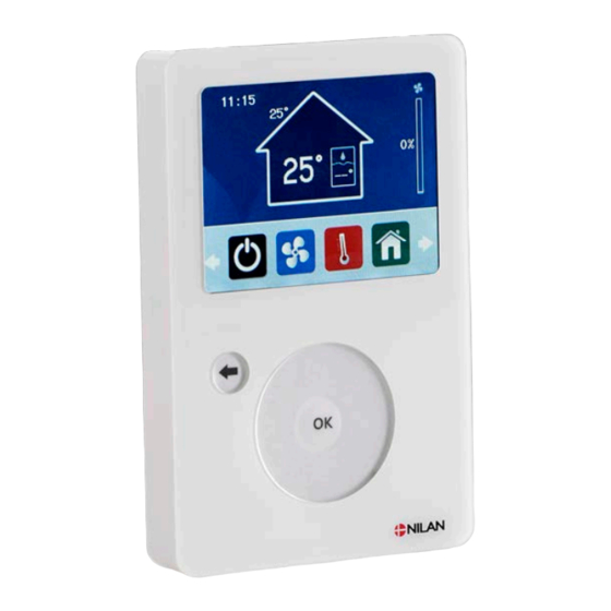
nilan CTS 700 Installation And Maintenance Manual

Advertisement

Installation and maintenance
CTS 700
by Nilan
Compact P GEO 3
Compact Polar GEO 6
Version: 1.02, 01-06-2016
We
Page 1 of 40
reserve the right to make changes

Advertisement

Table of Contents
loading

Summary of Contents for nilan CTS 700

  • Page 1 Installation and maintenance CTS 700 by Nilan Compact P GEO 3 Compact Polar GEO 6 Version: 1.02, 01-06-2016 Page 1 of 40 reserve the right to make changes...
  • Page 2: Table Of Contents

    Table of contents Table of contents ..........................2 General information before starting installation ................3 Safety ............................. 4 Compact P ............................5 The function ............................ 5 Installing Compact P ........................6 Condensation drain/water trap ......................9 Water connection .......................... 10 Power supply ..........................
  • Page 3: General Information Before Starting Installation

    Nilan dealer, by visiting The product is controlled by an CTS 700 control system, which provides a wide range of functions. Compact P is a heat recovery ventilation system with a capacity of up to 330m /h at 100Pa exter- nal counter pressure.
  • Page 4: Safety

    Safety Always disconnect the electrical supply to the heat pump if any malfunction occurs that cannot be remedied via the control unit. If any malfunction arises on the electrical part of the heat pump, always contact a licensed electrician to repair the fault. Avoid direct contact with the heating system pipes in the heat pump, as they can be very hot.
  • Page 5: Compact P

    Compact P The function  The installation of the plant must be performed by an authorized service technician or a field engineer who knows about heat pumps. Electrical installation/power supply (incl. Safety switch) must be installed by a certified electrician. The plant is connected according to the circuit diagram.
  • Page 6: Installing Compact P

    Installing Compact P  When installing the unit, it is important to take future service and maintenance into ac- count. There should be a minimum clearance of 60 cm in front of the unit, measured from the Compact P front panel. ...
  • Page 7 Figur 3: Sketch of Compact P The unit must be installed and leveled on a firm, vibration-free surface. There should be at least 10mm clearance to walls or other permanent installations. Although the unit itself is practically noise and vibration free, care must be taken to prevent any vibration from being propagated to ad- joining parts of the building.
  • Page 8 Outdoor air Inlet air Extract Yield Condenser Evaporator Supply air (after residual heat- TPanel ing surface) Supply air (before preheating surface) On residual heat surface T11: Top of container T12: Bottom of container TPanel: CTS700 control panel T13: Brine, flow T14: Brine, return T16:...
  • Page 9: Condensation Drain/Water Trap

    Condensation drain/water trap Compact P is supplied with 20mm condensation outlet (PVC, GF fittings). The unit is also equipped with built-in water trap.  The condensation outlet must be led frost-free with a steady decline of at least 1 cm/m to the nearest drain.
  • Page 10: Water Connection

    Water connection The inner tank surface is enamelled and the tank is equipped with a sacrificial anode. All connectors have 3/4” threads, with the exception of the anode access which is a 5/4” sleeve. All water pipes are connected to the bottom of the unit. If you wish, you can establish a hot water circulation system.
  • Page 11 Figur 6: Water connections Tilslutning for cirkulationsrør ¾” Anschluss für zirkulationrohr ¾” Circulation pipe connection ¾” Branchement à tuyeau de circulation ¾” Varmtvandsudtag ¾” Warm Wasser ¾” Hot water connection ¾” Sortie eau chaude ¾” Koldt vandsindtag ¾” Kalt wasser ¾” Cold water connection ¾”...
  • Page 12: Power Supply

    The Comfort-unit must be connected according to the attached electrical chart. The unit is delivered with 3 m test cable for the CTS 700 panel. The panel should be connected to the CTS 700 control in the unit with cable type cat 5e twisted in pairs. (Maximum length 20m).
  • Page 13: Duct Connection

    Duct connection Ducting and fittings with rubber seals of tightness class B are recommended. It is also advisable that all duct connections to Compact P be made with approx. 1m of soundproofed flex tube in order to dampen sound emission. Ducting should be cut to length using a hacksaw or angle grinder and laid in accordance with the design drawing.
  • Page 14: Supplementary Heating Element Dhw

    Supplementary heating element DHW The hot water tank has a supplementary heating element of 1,5kW. The heating element can be activated and de-activated via the CTS 700 control, see the “Settings → Compac → DHW settings” menu. The temperature, at which the heating element should be active (T11), can be set in the “Settings →...
  • Page 15: Fault Finding

    If problems arise during operation, please check the following before calling the service centre. Check that the alarm mark on the CTS 700 panel is displayed. If so, investigate the cause of the alarm and remedy the fault. If necessary, contact your local service centre. For details of alarms and how to reset them, please refer to the operating instructions for the CTS 700 controls.
  • Page 16: Operation And Maintenance

    The filters should be cleaned and renewed when needed. Usually the filters need to be renewed once every 3 month. The filter guard in the CTS 700 control can be used in order to make sure that the filters are checked. The filters can be cleaned by vacuuming or shaking them.
  • Page 17 Tilbehør Zubehör Accessories Accessoires Figur 10: Safety Switch Page 17 of 40 reserve the right to make changes...
  • Page 18: Energy-Saving Tips For The Optimal Operation

    Maintain a low temperature of the hot water. Try for example. at 45 ° C. The auxiliary heating element should be cut off and only be used at very large hot-water demands. Please see CTS 700 directions The ventilation speed should not be set higher than necessary.
  • Page 19: Geo 3 + Geo 6

    GEO 3 + GEO 6 System construction  Electrical installation/power supply (including safety switch) should be installed by an authorised electrician. Connect the unit according to the wiring diagram supplied. Figure 71: Example of system design Function of ground source heat system The Geothermal heat pump GEO is designed for heating homes with low temperature heating sys- tems with forward-flow temperatures of up to 45 °C, for example floor heating systems.
  • Page 20: Connection The Heat Pump

    Connection the heat pump Lable attached at the heat pump Page 20 of 40 reserve the right to make changes...
  • Page 21: Operation And Maintenance

    Operation and maintenance  When setting up the system, future service and maintenance should be taken into ac- count. Minimum clearance in front of the system of at least 1m is recommended. Starting the heat pump Before starting the heat pump, check the following: •...
  • Page 22: Pressure In Ground Source Loop (Ground Pipe)

    Pressure in ground source loop (ground pipe) The pressure must be inspected as often as several times a day in the initial days. If necessary, the system must be topped up with brine. See Figure 13, point 17 Brine pressure will stabilise after a few days and inspection can then be reduced to once a month. It is important that brine pressure is correct.
  • Page 23: Filling Water In The Central Heating Loop

    Filling water in the central heating loop • Switch off the heat and circulation pumps at the main switch. • Fill water into the central heating loop via the filler cock, Figure 13, item 13, until the correct water pressure is achieved, Figure 13, item 17 •...
  • Page 24: Function Description

    Function Description Heat pump compressor The system is protected with high and low-pressure switches that can stop the compressor and trigger an alarm. By heating demand the heat pump compressor starts when the temperature has dropped to set- point minus the neutral zone. When the compressor is operating the central heating temperature is raised up to the respective set point before it goes out.
  • Page 25: Permitted Area Of Action For The Heat Pump

    Make sure that the central heating system (e.g. the central floor heating system) is applied on a potential free input on CTS 700 to start/stop the heat pump. If input is not applied CTS 700 solely has to operate the heat pump. The central floor heating control must not start/stop the central heating pump directly! Mentioned below are examples using pump graphs for a Grundfos Alpha pump with different instal- lations of the pump control.
  • Page 26 Fixed pace: Run step 3 or a constant RPM control in the step that secures a circulation at a mini- mum of 20% of the design flow when there is not a heating need from the central heating system. Auto. Can be used if there is a fixed circulation. Do not work for a pressure controlled circulation valve.
  • Page 27: Frost Protection

    Frost protection A number of functions are built into the system to prevent frost damage. These functions are al- ways active regardless of the operating modes and settings selected (including OFF). Any missing or defective temperature sensors or system components can of course render this protection inef- fective: When the outside temperature falls below 2 °C, the central heating circulation pump will start.
  • Page 28: Event Log Menu

    Event log Menu The Event log displays any Event log and an alarm overview for the Event log. If an alarm is triggered, an alarm icon will show on the display. Menu: Information → Event log The alarm is displayed with an alarm code. To approve an alarm, press "Acknowledge"...
  • Page 29: Leakage

    Leakage The pressure is too low in the ground pipes/ground source loop. This may mean that the ground pipes are leaking. Check the following: 1. Are all cocks open that should be open? 2. Is there enough brine in the system? Top up if necessary. Check 1 –...
  • Page 30: Installation

    Installation Page 30 of 40 reserve the right to make changes...
  • Page 31 Compact P SHW GEO Sensor T2 is placed in sensor pocket at the top of SHW Page 31 of 40 reserve the right to make changes...
  • Page 32 Compact P Solar GEO Sensor T2 is placed in sensor pocket in the Compact tank next to the T11 sensor Figure 13: Structural ground source pump system diagram. Page 32 of 40 reserve the right to make changes...
  • Page 33: Electrical Connection Geo 3

    Electrical connection GEO 3 The heat pump must be connected to electrical installation by an authorised electrician. 2x400V, 2L+N+PE, 13 A, 50Hz Standard Supply cable: 4x min. 1.5 mm², HO5W-F 3x230V, 3L+PE, 13 A, 50 Hz Option Supply cable: 4x min. 1.5 mm², HO5W-F 1x230V, L+N+PE, 20 A, 50 Hz Option Supply cable: 3x min.
  • Page 34: Ground Source Loop

    Ground source loop When setting up a ground source loop, there are a number of clearance requirements which must be complied with to ensure efficient and trouble-free operation. Furthermore, local authorities often stipulate their own requirements for installation and approval of the system before it is commis- sioned.
  • Page 35 Figur 14: Eksempel på udlægning af jordslanger i samlebrønd Figure 15: Example of layout of ground pipes with collection inside footing. Page 35 of 40 reserve the right to make changes...
  • Page 36: Testing For Leaks

    Testing for leaks: As cracks in the pipes can occur during handling/transport, it is important to pressure test the pipes individually for leaks immediately before covering with earth. Testing for leaks should be carried out in accordance with the applicable regulations. Brine filling After completed and substantiated testing for leaks, the system can be filled with brine.
  • Page 37: Check List For Brine/Water Pump System At Start-Up And Commissioning

    Check list for brine/water pump system at start-up and commissioning The check list must be followed at start-up and commissioning of the complete heating system. Reference is made to the text in the manual for further details. Before the system is put into opereation the following item must be checked and notes made. Brine circuit Control Memo...
  • Page 38 Central heating circuit Control Memo Date Yes/No The heating circuit is tight? The heating circuit is purged of air after filling the sys- Pressure of the heating circuit, bar gauge The safety valve of the heating circuit is mounted cor- rectly and has correct opening pressure The is a bypass, which ensures a sufficient flow through the condenser (eliminates HP cut-out)
  • Page 39 Electircal supply and controls Control Memo Date Yes/No The mains supply, protection and connection, must be according to the wiring diagram and manual. Chosen form of regulation in the control, fixed or varia- Fixed ble heating temperature Variabel Selected setpoint Elected curve for central heating tem- °C perature curve...
  • Page 40: Accessories / Spare Parts

    ≥0.20 m3/h (0.06 l/s) A flow circuit at a minimum of 20% of the design flow. Accessories / spare parts Filters Type Antal Nilan varenummer Filter G4 39167 Pollen filter F7 39545 Figur 16: Accessories/spare parts Page 40 of 40...

This manual is also suitable for:

Compact p geo 3Compact polar geo 6

Table of Contents