Vaillant ecoTEC plus Setup Instructions
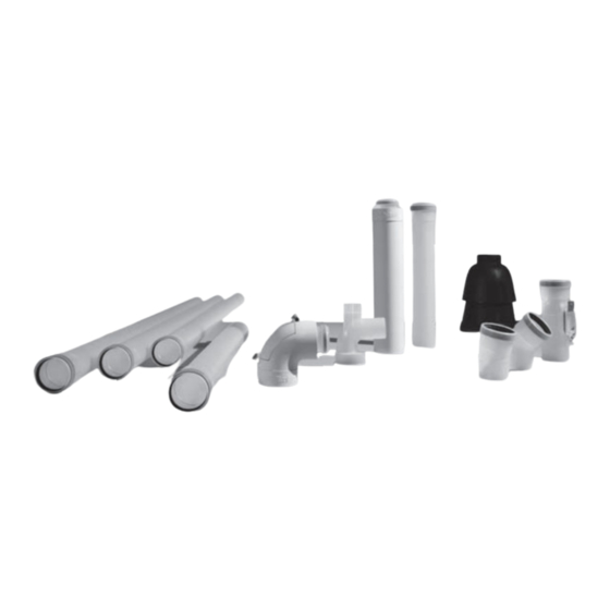
Air/flue systems
Hide thumbs
Also See for ecoTEC plus:
- Installation and maintenance instructions manual (92 pages) ,
- Installation and maintenance manual (56 pages) ,
- Instructions for installation and servicing (52 pages)
Table of Contents


Need help?
Do you have a question about the ecoTEC plus and is the answer not in the manual?
Questions and answers