Table of Contents
Advertisement
Advertisement
Table of Contents

Related Manuals for Vaisala SPS311


Summary of Contents for Vaisala SPS311
- Page 1 TECHNICAL REFERENCE Vaisala Sounding Processing Subsystem SPS311 M210651EN-G...
- Page 2 The contents are subject to change without prior notice. Please observe that this manual does not create any legally binding obligations for Vaisala towards the customer or end user. All legally binding commitments and agreements are included exclusively in the applicable supply contract or Conditions of...
-
Page 3: Table Of Contents
Trademarks ................10 License Agreement ..............10 Warranty.................. 10 CHAPTER 2 PRODUCT OVERVIEW................11 Introduction to SPS311............11 Sounding Subsystem with MRP111....... 12 Sounding Subsystem with MRP121 and MPU121 ..12 Front Panel................13 General................13 Power Control Switch............13 Indicator LEDs.............. - Page 4 TECHNICAL REFERENCE ________________________________________________________ Power Supply and Grounding ..........23 Cable Connections ..............24 Configuring the Network Connections.........25 Creating the Connection with NetMeeting......25 Configuring NetMeeting..........26 Creating a Connection with NetMeeting......26 Connecting to MWI210 in RT20A with NetMeeting...29 Creating the Connection with Remote Desktop Connection ..........29 Creating the Connection with VNC ........30 Creating the Connection with HyperTerminal or PuTTYtel ...........31...
- Page 5 ________________________________________________________________________________ CHAPTER 8 TECHNICAL DATA ..................53 Specifications ................. 53 APPENDIX A EU DECLARATION OF CONFORMITY ............55 VAISALA ________________________________________________________________________ 5...
- Page 6 TECHNICAL REFERENCE ________________________________________________________ This page intentionally left blank. 6 ___________________________________________________________________ M210651EN-G...
-
Page 7: Chapter 1 General Information
This chapter provides general notes for the manual and the product. About This Manual This manual provides information for installing, operating, and maintaining Vaisala Sounding Processing Subsystem SPS311. Contents of This Manual This manual consists of the following chapters: - Chapter 1, General Information, provides general notes for the manual and the product. -
Page 8: Version Information
TECHNICAL REFERENCE ________________________________________________________ - Chapter 8, Technical Data, provides the technical data of SPS311. - Appendix A, provides the full EU declaration of conformity. Version Information Table 1 Manual Revisions Manual Code Description M210651EN-G This manual. M210651EN-F Previous version. M210651EN-E Old version. -
Page 9: Feedback
Product Related Safety Precautions The SPS311 delivered to you has been tested for safety and approved as shipped from the factory. Note the following precautions: WARNING Ground the product, and verify outdoor installation grounding periodically to minimize shock hazard. -
Page 10: Recycling
License Agreement All rights to any software are held by Vaisala or third parties. The customer is allowed to use the software only to the extent that is provided by the applicable supply contract or Software License Agreement. -
Page 11: Chapter 2 Product Overview
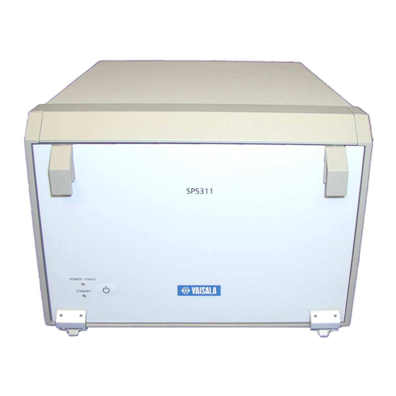
Chapter 2 ________________________________________________________Product Overview CHAPTER 2 PRODUCT OVERVIEW This chapter introduces the features and units of SPS311. Introduction to SPS311 Vaisala Sounding Processing Subsystem SPS311 is a subsystem for the DigiCORA® Sounding System. It consists of Front Panel, Chassis, Plug-In Units and Connector Panel. -
Page 12: Sounding Subsystem With Mrp111
TECHNICAL REFERENCE ________________________________________________________ Sounding Subsystem with MRP111 The basic Sounding Subsystem with the MRP111 unit (PTU only) contains: - Chassis Radio receiver units 400 MHz Receiver MRR111 Receiver Processor MRP111 Power supply units AC Power Supply MWP411 DC Power Supply MWP312 GPS system contains the following additional units: GPS Processor MRG111/MRG112 Loran-C system contains the following additional units:... -
Page 13: Front Panel
LED Color LED color blank blank power is not applied yellow blank power is applied blank blinking green powering up blank green ready for operation blank unit failure during power up or during operation, failure in network connection VAISALA _______________________________________________________________________ 13... -
Page 14: Power Control Dip Switches
TECHNICAL REFERENCE ________________________________________________________ NOTE If there is no network connection between the SPS311 and the Sounding Workstation the Power/Status indicator LED is lit red and green in turn in slow sequence. Check the physical network connections and the network configuration as described in Chapter 3 “Configuring the Network Connections”. - Page 15 RACK0#, where RACK1# is MSB (most significant bit) and RACK0# is LSB (least significant bit). Table 5 Rack Identification DIP Settings Rack Address S3-1 OFF, S3-2 OFF S3-1 ON, S3-2 OFF S3-1 OFF, S3-2 ON S3-1 ON, S3-2 ON VAISALA _______________________________________________________________________ 15...
-
Page 16: Chassis And Plug-In Units
TECHNICAL REFERENCE ________________________________________________________ Chassis and Plug-In Units Unit slots The chassis contains a card frame with nine unit slots, motherboard and I/O extension board. The slots are numbered from left to right (front view) with numbers 1 through 9. Plug-in Units with MRP111 Configuration The plug-in units used in the MRP111 configuration are shown in Figure 3 and Figure 4. - Page 17 External power unit 212822MW (or equivalent) is needed to provide the feeding voltage. The external power is connected to VDC IN 24 V on the rear panel of the SPS311. In the Loran-C system the replacement of MWP411 also releases slot 9 for MWV2xx.
-
Page 18: Plug-In Units With Mrp121 And Mpu121 Configuration
Plug-in Units with the MRP121 and MPU121 Configuration - GPS Option The units are located in the chassis as described in the following table. Table 7 SPS311 Unit Slots with the MRP121/MPU121 Slot Unit with GPS Unit with LORAN-C MRR111... -
Page 19: Motherboard
The panel includes I/O Connectors, a printed circuit board which connects the I/O signals between and I/O Extension board. Antenna signals and LAN are connected via cables to the plug-in units and the power inputs are wired from connector to the motherboard. VAISALA _______________________________________________________________________ 19... - Page 20 TECHNICAL REFERENCE ________________________________________________________ 0410-158 Figure 6 The power, signal and I/O connectors located at the rear of the SPS311 Table 8 Connector panel connectors Connector Description Note AC-LINE Mains power connector VDC IN 24V DC power connector UHF ANTENNA UHF antenna connector...
-
Page 21: Ac-Line
NOTE +12 VDC power is supplied to the antenna. GPS Antenna Connector type: Coaxial TNC female NOTE NOTE +5 VDC power is supplied to the antenna. VLF Antenna Connector type: Coaxial C female NOTE NOTE +12 VDC power is supplied to the antenna. VAISALA _______________________________________________________________________ 21... -
Page 22: Lan1
TECHNICAL REFERENCE ________________________________________________________ LAN1 Connector type: RJ-45 Connector (Neutrik NE8FAV) Table 10 LAN Connections Signal Note Transmit data + Transmit data – Receive data + Receive data – NOTE LAN2 can be used only if MPU112/MPU111 or MRP121/MPU121 is installed in rack. CTRL Connector type: 9 pin D female... -
Page 23: Chapter 3 Installation
This chapter provides you with information about installing and configuring this product. General SPS311 is a desktop instrument intended for use in the office or inside a container. It can easily be fastened to an installation shelf by using mounting straps:... -
Page 24: Cable Connections
System ground screw Mains power and 24VDC system power are alternative power sources NOTE and need not to be used at the same time. For more information on the cable connections of SPS311, refer to DigiCORA® Installation Manual. 24 __________________________________________________________________ M210651EN-G... -
Page 25: Configuring The Network Connections
For the details on creating the connection, see the following sections. Creating the Connection with NetMeeting The NetMeeting program is delivered with the workstation's operating system. If there is no shortcut for NetMeeting on the desktop or launch bar, you need to configure the program. VAISALA _______________________________________________________________________ 25... -
Page 26: Configuring Netmeeting
Creating a Connection with NetMeeting To create a connection with NetMeeting you have: - MRP111 or MPU121/MPU112/MPU111 in the SPS311 and a connection from it to the workstation via Ethernet - MWI210 in SPS220 and a connection from it to the workstation via Ethernet - Other operating system than Windows Vista. - Page 27 Enter the unit's default IP address in the To box and click Call. - MRP111: 192.168.0.10 - MPU: 192.168.0.20 - In SPS220, MWI210: 192.168.0.20 Log on to the system by entering the following information: Leave Domain empty by default. - Username: administrator - Password: Administrator - Domain: <empty> VAISALA _______________________________________________________________________ 27...
- Page 28 TECHNICAL REFERENCE ________________________________________________________ Start the RegConfig program on the unit by clicking the Start button and selecting Run. 0204-047 Figure 7 Starting the RegConfig Program Type regconfig in the Open text box and click OK. Information on using the RegConfig program can be found in section RegConfig Program on page 34 .
-
Page 29: Connecting To Mwi210 In Rt20A With Netmeeting
Creating the Connection with Remote Desktop Connection To create a connection with Remote Desktop Connection you have: - MPU121 or MPU112 in the SPS311 and a connection from it to the workstation via Ethernet - Windows Vista operating system. Remote desktop connection can only be used for units MPU112 or NOTE MPU121. -
Page 30: Creating The Connection With Vnc
Logoff button. Creating the Connection with VNC To create a connection with VNC you have: MRP111 in the SPS311 or MWI210 in the SPS220 and a connection from it to the workstation via Ethernet Windows Vista operating system. VNC connection can only be used for MRP111 or MWI210 units. -
Page 31: Creating The Connection With Hyperterminal Or Puttytel
- MRP111 or MPU121/MPU112/MPU111 or MWI210 and have forgotten the unit's IP address and therefore are not able to connect to the unit using NetMeeting. - Windows Vista operating system with the following cards: MWI210, MRP111, or MPU111, and therefore unable to use NetMeeting. VAISALA _______________________________________________________________________ 31... - Page 32 Connect the workstation's COM port to the units COM1 connector with cable MW45042. If you have the MPU121 unit, connect to the COM2 connector of the SPS311. Start the program: - If you use HyperTerminal, select Start - Programs - Accessories - Communications - HyperTerminal.
- Page 33 If you use PuTTYtel, close the program. - MPU121/MPU112: Press ENTER until you get the message "Regconfig exit". o If you use HyperTerminal, select Call - Disconnect and close the program. o If you use PuTTYtel, close the program. VAISALA _______________________________________________________________________ 33...
-
Page 34: Regconfig Program
Default Gateway Default gateway of the unit's 0.0.0.0 0.0.0.0 embedded PC Change this only when needed. Vaisala Name Server IP IP-address of the Vaisala Name 192.168.0.1 192.168.0.1 Server. This is the IP-address of the Sounding Workstation = DigiCORA PC. NOTE... -
Page 35: Chapter 4 Operation
Getting Started Switching the power on and off The power switch of the SPS311 is located on the lower left corner of the front panel. The power switch is marked with symbol Before the Subsystem power can be switched on the system must be in standby state. - Page 36 TECHNICAL REFERENCE ________________________________________________________ Red color indicates an error in one or more units during the power up or operation. Red color can also be an indication of the IP- configuration failure. See chapter Configuring the Network Connections. 36 __________________________________________________________________ M210651EN-G...
-
Page 37: Updating The Software
Switching off the unit before the update is finished may cause serious malfunction. Switch on the Sounding Workstation and the SPS311 and wait until the system is ready for operation. Place the Setup CD into the CD-ROM drive of the Sounding Workstation and click Start, select Run and click the Browse button. -
Page 38: Verifying The Mrp111 Software Update
"Vaisala Embedded Software Update complete" is displayed. Press any key and the window will close. Switch the SPS311 power off and on again to complete the update. It is recommended that the update is verified. See the next section Verifying the MRP111 Software Update. -
Page 39: Checking The Software Version Of Mrp111
Checking the Software Version of MRP111 To check the software version installed on MRP111 card, do the following: Switch on the Sounding Workstation and the SPS311 and wait until the system is ready for operation. Place the Update CD into the CD-ROM drive of the workstation. -
Page 40: Verifying The Mpu121/Mpu112/Mpu111 Software Update
"Vaisala Embedded Software Update complete" is displayed. Press any key and the window will close. Switch the SPS311 power off and on again to complete the update. It is recommended that the update is verified. See the next paragraph Verifying the MPU121/MPU112/MPU111 Software Update. -
Page 41: Checking The Software Version Of Mpu121/Mpu112/Mpu111
MPU121/MPU112/MPU111 To check the software version installed on MPU121/MPU112/MPU111 card, do the following: Switch on the Sounding Workstation and the SPS311 and wait until the system is ready for operation. Place the Update CD into the CD-ROM drive of the workstation. -
Page 42: Mwv201 Software Update
MWV201 Software Update The update CD contains latest version of unit software for MWV201. Switch on the Sounding Workstation and the SPS311 and wait until the system is ready for operation. Place the Setup CD into the CD-ROM drive of the workstation. -
Page 43: Chapter 6 Maintenance
In all maintenance work, remember to proceed in accordance with electrical safety regulations. WARNING Switch SPS311 POWER OFF before replacing any plug-in units. Unplug the mains connector before replacing the AC power supply MWP411. Switch External 24 VDC supply OFF before replacing the DC power supply MWP312 Or MWP302. -
Page 44: Replacing Fuses
TECHNICAL REFERENCE ________________________________________________________ Replacing Fuses General The fuses should be checked if the power is connected to SPS311, but the ‘Standby’ LED on the Front Panel remains blank. There are three user-replaceable fuses in the System, two in connection with the AC power inlet and one in the DC Power Supply MWP312. -
Page 45: Replacing Dc Power Unit Fuses
The DC Power unit MWP312 has a user-replaceable fuse in the main 24 V input. Remove the MWP312 unit as instructed in “Replacing the Plug- in Units”. The fuse is located in a hole on in the middle of the cooling plate of the unit. VAISALA _______________________________________________________________________ 45... - Page 46 TECHNICAL REFERENCE ________________________________________________________ Lift the other end of the fuse carefully with the tip of the screwdriver as shown in the Figure 10 and remove it with fingers. Figure 10 Removing the fuse from MWP312 Replace the fuse if needed. The type of the fuse is T5A250V. 46 __________________________________________________________________ M210651EN-G...
- Page 47 Figure 11 and the Figure 12. Figure 11 Dropping the fuse to the holder in MWP312 Figure 12 Pressing the fuse to its place into MWP312 Install the MWP312 unit as instructed in “Replacing the Plug-in Units”. VAISALA _______________________________________________________________________ 47...
-
Page 48: Replacing Batteries
TECHNICAL REFERENCE ________________________________________________________ Replacing Batteries The MPU112/MPU111 contains a lithium battery for the calendar clock. Replacement of the battery may be needed after 10 years of operation. The MPU121 battery does not need changing. WARNING If the battery of the MPU112/MPU111 is replaced, please note that lithium batteries can cause fire and burn hazard. -
Page 49: Checking The Operation Of Cooling Fans
Move the unit slowly in card guides and avoid bending. Checking the Operation of Cooling Fans A rough check can be done by switching the SPS311 on/off and observing the audible noise of the fans when power is on. A full check can be done by removing all plug-in units except MWP312 and connecting the SPS311 to 24 VDC power system using the 24V DC input in the connector panel. - Page 50 TECHNICAL REFERENCE ________________________________________________________ This page intentionally left blank. 50 __________________________________________________________________ M210651EN-G...
-
Page 51: Chapter 7 Troubleshooting
- Input power source type, voltage and list of other items (lighting, heaters, motors etc.) that were connected to the same power output. - What was done when the failure was noticed? Technical Support For technical questions, contact the Vaisala technical support: E-mail helpdesk@vaisala.com +358 9 8949 2790... - Page 52 If the product needs repair, please follow the instructions below to speed up the process and to avoid extra costs to you. Read the warranty information. Contact Vaisala technical support via e-mail or fax and request for RMA (Return Material Authorization) and shipping instructions.
- Page 53 Chapter 8 __________________________________________________________Technical Data CHAPTER 8 TECHNICAL DATA This chapter provides the technical data of SPS311. Specifications Table 16 SPS311 Specifications Property Description / Value Dimensions 235 x 323 x 183 mm Power consumption 70 W max. Mains voltage 90 ... 132 V or 175 ... 264 V Mains frequency 47 …...
- Page 54 TECHNICAL REFERENCE ________________________________________________________ This page intentionally left blank. 54 __________________________________________________________________ M210651EN-G...
- Page 55 Appendix A ______________________________________________EU Declaration of Conformity APPENDIX A EU DECLARATION OF CONFORMITY The full EU declaration of conformity can be found on the next page. VAISALA _______________________________________________________________________ 55...
- Page 56 TECHNICAL REFERENCE ________________________________________________________ 56 __________________________________________________________________ M210651EN-G...
- Page 57 Appendix A ______________________________________________EU Declaration of Conformity This page intentionally left blank. VAISALA _______________________________________________________________________ 57...
- Page 59 www.vaisala.com...
Need help?
Do you have a question about the SPS311 and is the answer not in the manual?
Questions and answers