Table of Contents
Advertisement
Quick Links
Advertisement
Table of Contents

Related Manuals for Brillion HFC Series

Summary of Contents for Brillion HFC Series
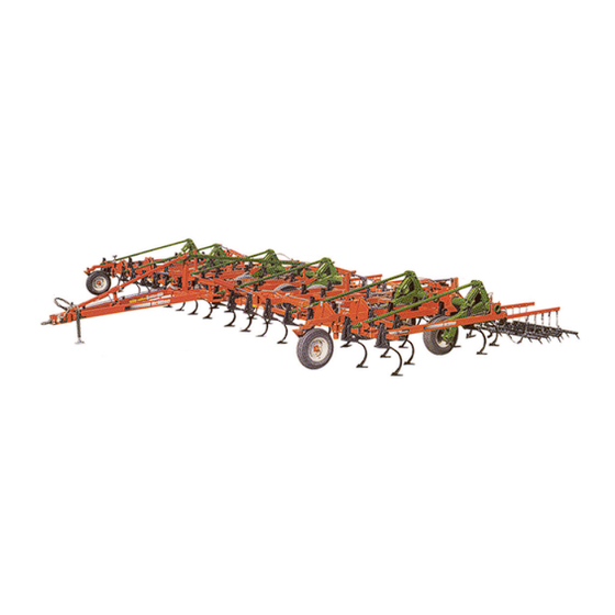
- Page 1 ASSEMBLY INSTRUCTIONS OPERATOR’S MANUAL rillion rillion WIDE (37-Foot through 45-Foot) HFC Field Cultivator MODELS: HFCT37 THROUGH HFCT45 HFKT37 THROUGH HFKT45 BRILLION BRILLION, WISCONSIN 54110 5K094 rev3-31-05 www.brillionfarmeq.com...
-
Page 3: Table Of Contents
ontents Contents Introduction ............................3 Location reference ........................3 Parts ordering ..........................3 Safety Suggestions ........................4 Safety Warning Signs ........................5 Decal locations ........................7 Pre-operating Checks ........................8 Operating Instructions .........................12 Safety chain ........................12 Prepare for transport ......................12 Prepare for field operation .....................13 Operating depth adjustment ....................13 Maintenance ..........................15 Fasteners ..........................15 Shanks ..........................15... -
Page 5: Introduction
To obtain maximum benefits from the BRILLION FIELD CULTIVATOR, please study this manual carefully before starting assembly or operation. A special section, “Assembly Instructions”, is included. If items in this manual are not understood, contact your local Brillion dealer The Symbol Shown Is Used To Call Your Attention To Instructions Concerning Your Personal Safety. -
Page 6: Safety Suggestions
SAFETY SUGGESTIONS Federal law requires you to explain the safety and operating instructions furnished with this machine to all employees before they are allowed to operate the machine. These must be repeated to the em- ployees at the beginning of each season. Be sure to observe and follow the instructions for the safety of anyone operating or near the machine. -
Page 7: Safety Warning Signs
SAFETY WARNING SIGNS The “WARNING” signs and their locations illustrated on the following two pages are placed on the ma- chine to warn of hazards. “The warnings found on the signs are for your own personal safety and that of those around you.” OBSERVE THESE WARNINGS! There are three levels of hazard intensity that appear with the safety alert symbol on safety decals: DANGER, WARNING, and CAUTION. - Page 9 Page 7 5K094 rev3-23-05...
-
Page 10: Pre-Operating Checks
PRE-OPERATING CHECKS Hydraulic cylinders Before raising or lowering the wings, be sure that the wing lift cylinders are properly bled (all air is removed from the hydraulic circuit). Improperly bled cylinders will permit the wings to free-fall, possibly causing injury to the operator and damage to the machine. - Page 11 Extend the cylinders and hold the control lever in the extend position until there is no motion in any of the cylinders. Check the pin center distances. If they are not all approximately 28 1/4”, retract the cylinders and disconnect the pins from the wheel arms and the cylinder anchors.
- Page 12 CENTER ROCKSHAFT FIGURE 4 BRACE TURNBUCKLE LINKAGE LEVELING ADJUST CENTER FRAME DRAWBAR If the point to ground distance is not the same in the front as in the rear, level the machine by adjusting the drawbar leveling turnbuckle. Now adjust each wing cylinder depth adjust rod so that the tooth points of each wing section are the same distance from the ground as those on the center section.
- Page 13 After each adjustment, completely raise the field cultivator, hold the hydraulic control in he extend position, and then lower the machine until the tooth points are just barely off the ground. Note: During the leveling procedure, the front gage wheel is not supporting the frame and the outside front teeth of the cultivator wing may touch the ground first.
-
Page 14: Operating Instructions
Replace chain if one or more links are broken, stretched, or otherwise damaged or deformed. Keep attaching hardware fastened securely. If bolts are replaced, be sure to use grade 5 or higher. If you have any questions regarding the safety chain call your Brillion dealer. Page 12 5K094 rev3-23-05... -
Page 15: Operating Depth Adjustment
CAPSCREW, 1/8” x 3 3/4” SPOOL STOVER NUT, 1-8 9” MAXIMUM CHAIN FIGURE 6 TRACTOR DRAWBAR Prepare the machine for field operation 1. Raise the machine fully on its transport wheels. 2. Flip the transport locks on both center axle lift cylinders into their storage positions. 3. - Page 16 INDICATOR DIMENSION NOTE: SCALE “X” THESE ARE APPROXIMATE DIMENSIONS. READING (OPERATING VERIFY OPERATING DEPTH BY MEASUR- DEPTH) ING PENETRATION OF TOOTH INTO THE GROUND. 0” ONE TURN OF THE DEPTH ADJUST 1 1/4” ROD EQUALS 5/16” DIFFENCE IN 2 3/4” OPERATING DEPTH.
-
Page 17: Maintenance
MAINTENANCE Fasteners After a few hours use, check entire machine and tighten any loose nuts or bolts. Daily or periodic checks should be made thereafter. Shanks After 5 hours of operation, and every 50 hours thereafter, check to make sure that the shank pivot bolts are tight. -
Page 19: Assembly Instructions
ASSEMBLY INSTRUCTIONS ASSEMBLE CENTER FRAME AND DRAWBAR Note: After machine is completely assembled, lubricate it according to figure 9. This will prevent corrosion during storage. 1. Select a smooth level area that can be reached by a hoist or lift truck. 2. - Page 20 CENTER FRAME HALF LINK ROLL PIN 1/2” x 2” 1 7/16” x 10 1/4” DRAWBAR MANUAL DRAWBAR ROLL PIN CANNISTER JACK (Stored) 1/2” x 2 “ 1 7/16” x 10 1/4” CENTER FRAME HALF FIGURE 11 6. Position the sleeves of the drawbar between the lugs on the center frames. Insert the 1 7/16”...
- Page 21 ANGLED GREASE FITTING 3/4” LOCKNUT, CYLINDER FIGURE 12 GENEROUSLY GREASE BEARING THESE SURFACES STOPS BOLT, (Insert from bottom) 3/4” x 14” BEARING WHEEL FRONT OF MACHINE...
- Page 22 Assemble the adjust tubes as follows, noting also the additional statements on page 20a: 1. Attach a left hand screw anchor (part #4K301) to the left front side of the center frame and a right hand screw anchor (part #4K302) to the right front side of the frame. (The right hand assembly is shown below;...
- Page 23 SPECIAL DEPTH ADJUST MECHANISM ASSEMBLY - CENTER SECTION HFC32 & LARGER It has been determined that use of certain components could contribute to damage to the axle tube. Therefore, on the CENTER SECTION ONLY, when assembling the depth adjust mechanism (HFC 32 through HFC 45), Do not use: The 2 3/4”...
- Page 24 4. Thread the adjust screw into the adjust tube. When the hole in the threaded portion of the adjust screw aligns with the hole in the adjust tube, insert a 3/16” x 1 1/2” roll pin through the access hole in the adjust tube into the hole in the screw.
- Page 25 ATTACH THE BRACE AND TURNBUCKLE BETWEEN THE ROCKSHAFT AND THE DRAWBAR 1. Place the sleeve of the 4K309 brace between the two lugs at the center of the rockshaft. Use the 1 3/8” diameter x 7 1/2” long pin to fasten the brace to the rockshaft. Secure the pin with two 5/16” x 2 1/2”...
- Page 26 OFFSET TO REAR FIGURE 16 CYLINDER ANCHOR LOCK NUT, 5/8” U-BOLT 5/8” CYLINDER ANCHOR LOCKNUT 5/8” FRONT OF U-BOLT MACHINE 5/8” ATTACH CYLINDER ANCHOR TO THE CENTER FRAME 1. Center a cylinder anchor over the front and rear toothbars of the center frames. The cylinder anchors are not symmetric and must be mounted with the cylinder mounting lug offset to the REAR of the cultivator.
- Page 27 ATTACH THE WINGS TO THE CENTER FRAME Adjust the center frame so that it is horizontal. Attach the wing sections as instructed to keep the assembly balanced. Each wing consists of a front half, a rear half, and an outer wing. 1.
- Page 28 ATTACH CYLINDERS TO THE CYLINDER ANCHORS 1. Connect the clevis ends of the four 4” x 30” long hydraulic cylinders to the cylinder anchors on the machine center. Position the cylinders with the ports facing the back of the machine as shown in the drawing below.
- Page 29 MOUNT THE WING GAGE WHEELS TO EACH WING Do not tighten any hardware until told to do so. If not already mounted, mount (4) 9.5L-15 6-Ply tires to 8” wide rims, then attach them to the walk ing beams of each wing rockshaft assembly. (This step is not shown in the drawing below. See center rockshaft drawing if needed.) 2.
- Page 30 The screw anchors and adjust tubes of the wings are assembled in the same manner as on the center frame EXCEPT: 1. The screw anchors are used on opposite sides. 2. A different hole is used when putting the scale on the collar. 3.
- Page 31 The hydraulic circuit which controls the gage wheel uses a pair of series hydraulic cylinders. This means that it is extremely important to install the cylinders exactly as directed. 6. Attach one cylinder with the number 2K094 stamped on it to each of the cylinder anchors of each wing axle assembly.
- Page 32 MOUNT THE GAGE WHEEL ONTO THE FRONT WING 1. Mount the gage wheel arms to the front wings as shown in Figure 20. The illustration shows the assembly for the left wing; mount the assembly to the right wing in the same way.
-
Page 33: Shanks
SHANKS Assemble the sweeps or points to the shanks before mounting the shanks. Note: The field cultivator is designed for using 9” wide sweeps, if wider sweeps are used, be sure to check clearances around all tires in both the operating and transport positions. 6K262 - QUICK-CHANGE POINTS Assemble the Quick-Change 1. - Page 34 Spring Loaded Shanks: To mount the spring loaded shank on your Field Cultivator, use the following procedure: 1. Remove the tensioning bolt from the spring assembly 2. Rotate the spring out of the spring holder bracket. 3. Remove the nuts from the U-bolt, and then also remove the U-bolt. 4.
- Page 35 MOUNTING SHANKS WHERE A PLATE BACKS A TUBE METHOD OF MOUNTING SHANKS AT SECOND RANK OF EACH WING FOLLOW THE NORMAL PROCEDURE FOR TO MOUNT THE 2-PIECE S-TINE SHANK, MOUNTING THE SPRING LOADED SHANK USE THE PLATES. STRAPS AND BOLTS IN BUT USE THE TOW BOLTS IN PLACE OF PLACE OF THE CLAMP, CLIP AND THE U-BOLTS...
- Page 36 Page 32 5K094 rev3-23-05...
- Page 37 Page 33 5K094 rev3-23-05...
- Page 38 This Page Left Blank Intentionally Page 33a 5K094 rev3-23-05...
-
Page 39: Hydraulics
ASSEMBLING THE HYDRAULICS Follow exactly the schematic drawings on the following two pages and the larger ones found in the instruction packet to avoid tangling or breaking the hoses or damaging the system. The assembly instructions are divided into two parts - the gage wheel hydraulics show the hose routing for raising and lowering the machine;... - Page 40 Page 34 5K094 rev3-23-05...
- Page 42 INSTRUCTIONS FOR #4K820 WARNING LIGHT KIT #4K751 MACHINE SCREW 1/4” x 3” #7K383 BRACKET WELDMENT #4K773 R.H. LAMP #6C729 LOCK NUT, 3/4” ASSEMBLY #4K772 L.H. LAMP ASSEMBLY #6J150 REAR 1/4” LOCKNUT #3J598 BEARING CASTING CENTER FRAME OF FIELD CULTIVATOR #4K299 MACHINE BOLT, 3/4”...
- Page 43 #2K501 CAPSCREW 1/4” x 2 1/2” WISHBONE WIRING HARNESS #4K826 TANDEM HAUL ADAPTER TO L.H. LAMP ASSEMBLY STRAIGHT SECTION WIRING HARNESS #4K339 REAR HITCH WELDMENT TRACTOR #6J150 1/4” LOCKNUT REAR TO R.H. LAMP ASSEMBLY If your Field Cultivator is equipped with a rear hitch, for tandem towing another implement, you’ll need to assemble the #4K826 tandem haul adapter to the rear hitch as shown .
-
Page 44: Spike Tooth Drags
Bolt the support chains of the drag assembly to the drag supports using 7/16 x 3 1/2” long capscrews with a flat washer and a 7/16” locknut. On Brillion Field Cultivators, support the drags by the fourth link from the end (3 links are left hanging). - Page 45 Page 37 5K094 rev3-23-05...
- Page 46 Page 38 5K094 rev3-23-05...
- Page 47 Page 39 5K094 rev3-23-05...
- Page 48 Page 40 5K094 rev3-23-05...
- Page 49 Page 41 5K094 rev3-23-05...
- Page 50 Page 42 5K094 rev3-23-05...
- Page 51 This Page Left Blank Intentionally Page -- 5K094 rev3-23-05...
- Page 52 COIL TINE HARROWS Refer to the location charts on pages 44-48. These drawings show the location of the carrier arms on the rear toothbar of the cultivator and the location and sizes of the coil tine sections. The 57” wide and 72”...
- Page 53 Page 44 5K094 rev3-23-05...
- Page 54 Page 45 5K094 rev3-23-05...
- Page 55 Page 46 5K094 rev3-23-05...
- Page 56 Page 47 5K094 rev3-23-05...
- Page 57 Page 48 5K094 rev3-23-05...
-
Page 58: Trouble Shooting
5 pounds. Extremely hard ground Use Heavy duty, 2 inch wide reversible points in place of sweeps (Brillion part no. 2J605), and/or make 2 passes with the first at a shallower depth. Shanks stretching Shank pivot is seized Free up the pivot and lubricate. - Page 59 Hoses not connected properly See charts on pages 34 & 35. Hydraulic hose ends not working properly Replace hose ends Wings do not fold properly Too fast Make sure restrictors are installed in the circuit. Too slow Check tractor flow adjustment and hydraulic pressure. 2000 PSI is required to fold large machines with spike tooth harrows mounted to rear tooth bar.
-
Page 60: Specifications
SPECIFICATIONS (Subject to change for product improvement) Model Designation The basic model designations are: “HFCT” High clearance Field Cultivator, equipped with Tandem wheels on center and wings. The numbers following the letters indicates the approximate machine width in feet between the centers of the two outermost shanks on the machine. - Page 61 5K094 rev3-23-05...
- Page 64 Equipment from Landoll Corporation is built to exacting standards ensured by ISO 9001:2008 registration at all Landoll manufacturing facilities. LANDOLL CORPORATION 1900 North Street Marysville, Kansas 66508 (785) 562-5381 800-428-5655 ~ WWW.LANDOLL.COM Copyright 2010. Landoll Corporation "All rights reserved, including the right to reproduce this material or portions thereof in any form"...
Need help?
Do you have a question about the HFC Series and is the answer not in the manual?
Questions and answers