
Related Manuals for Harman AMX DVX Series


Summary of Contents for Harman AMX DVX Series
- Page 1 INSTRUCTION MANUAL ALL-IN-ONE PRESENTATION SWITCHERS DVX-3266-4K DVX-2265-4K AV FOR AN IT WORLD...
- Page 2 Important Safety Instructions READ these instructions. KEEP these instructions. HEED all warnings. FOLLOW all instructions. DO NOT use this apparatus near water. CLEAN ONLY with dry cloth. DO NOT block any ventilation openings. Install in accordance with the manufacturer's instructions. DO NOT install near any heat sources such as radiators, heat registers, stoves, or other apparatus (including amplifiers) that produce heat.
- Page 3 1. Do not expose this apparatus 6. Clean this apparatus to rain, moisture, dripping or only with dry cloth. splashing and that no objects filled with liquids, such as vases, shall be placed on the apparatus. 7. Unplug this apparatus 2.
- Page 4 WARNING: This product is intended to be operated ONLY from the voltages listed on the back panel or the recommended, or included, power supply of the product. Operation from other voltages other than those indicated may cause irreversible damage to the product and void the products warranty. The use of AC Plug Adapters is cautioned because it can allow the product to be plugged into voltages in which the product was not designed to operate.
- Page 5 FCC SDOC SUPPLIER’S DECLARATION OF CONFORMITY HARMAN International hereby declares that this equipment is in compliance with the FCC part 15 Subpart The declaration of conformity may be consulted in the support section of our web site, accessible from www.
-
Page 6: Table Of Contents
CONTENTS INTRODUCTION ....................................3 OVERVIEW ..........................................3 COMMON APPLICATION ....................................3 AUDIO PROCESSING ....................................... 3 INTEGRATED CONTROL ....................................3 BATTERY LIFE ........................................3 FEATURES ..........................................4 PACKAGE CONTENTS ......................................4 SPECIFICATIONS ........................................5 TRANSMISSION DISTANCE ................................... 7 INSTALLATION ....................................8 WIRING AND DEVICE CONNECTORS ............................ - Page 7 ICS LAN PORT ......................................... 22 USB PORT ......................................... 23 USB A/B PORTS ......................................23 ID PUSHBUTTON ......................................24 LAN 100/1000 ......................................... 24 POWER CONNECTOR ....................................25 AUDIO/VIDEO CONFIGURATIONS ............................... 26 OVERVIEW ..........................................26 USING THE FRONT PANEL BUTTONS ................................ 26 VIDEO SETTINGS ......................................
-
Page 8: Introduction
Introduction Overview The All-In-One Presentation Switchers combine all of the components you need to control/automate any environment into a simple, flexible, comprehensive solution including control, analog and digital audio/video inputs, audio and video switching, video scaling, local and remote distribution, plus audio mixing, and amplification - all in a single box. -
Page 9: Features
Features Video/Audio matrix switcher; Built in NetLinx Master Controller; Built-in scalers; Supports HDMI 2.0 with resolution up to 4K@60Hz 4:4:4 In/Out; Supports HDCP 2.2; Supports HDR when scaler is in bypass mode; Supports audio breakaway and embedding, audio DSP, mic mixer, 120W amplifier, Dante inputs and ... -
Page 10: Specifications
Specifications The following table lists the specifications for the Enova DVX-3266-4K/DVX-2265-4K All-in-One Presentation Switchers: Specifications Power AC 100-240V 50/60Hz, 10A DVX-3266-4K: 90 Watts typical without amplifier, 130 Watts typical average with amplifier Power Consumption DVX-2265-4K: 63 Watts typical without amplifier, 103 Watts typical average with amplifier NVRAM: 1 MB ... - Page 11 Specifications DVX-3266-4K: 2 RJ-45 outputs provide digital video, audio, Ethernet, bi-directional control, USB, and power over Twisted Pair Cable to DXLink Receivers. DXLINK OUTPUTs DVX-2265-4K: 1 RJ-45 outputs provide digital video, audio, Ethernet, bi-directional control, USB, and power over Twisted Pair Cable to DXLink Receivers.
-
Page 12: Transmission Distance
Specifications VIC = 29, 1440 x 576p 50 Hz 4:3 VIC = 30, 1440 x 576p 50 Hz 16:9 VIC = 31, 1920 x 1080p 50 Hz 16:9 VIC = 32, 1920 x 1080p 23.97/24 Hz 16:9 VIC = 33, 1920 x 1080p 25 Hz 16:9 VIC = 34, 1920 x 1080p 29.97/30 Hz 16:9 VIC = 39, 1920 x 1080i 50 Hz 16:9 VIC = 41, 1280 x 720p 100 Hz 16:9... -
Page 13: Installation
Installation Note: Before installation, please ensure the device is disconnected from the power source. Steps to install the device into an equipment rack: The DVX occupies two rack units in a standard equipment rack. The following steps apply to mounting the DVX. -
Page 14: Wiring And Device Connectors
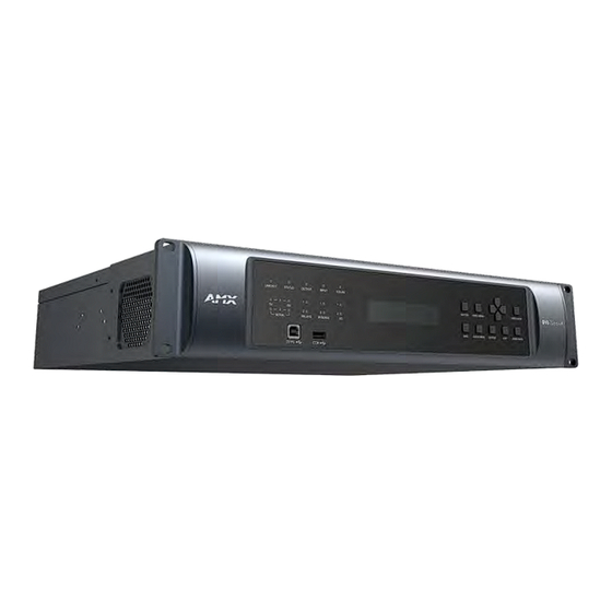
Wiring and Device Connectors Overview This chapter provides functional details for each item on the front and rear panel of the DVX. Wiring specifications are also provided, when applicable. Front View STATUS LED INPUT LED Navigational pushbu tt ons LINK/ ACT LED OUTPUT LED ICSLAN LED SWITCH Pushbutt on... -
Page 15: Front Panel Controls And Indicators
Front Panel Controls and Indicators The following sub-sections describe each component on the front panel of the DVX. Refer to FIG. 1 for the component layout of the front panel. LEDs The LEDs on the front panel indicate the communications status of several different connections. as described in the table below: STATUS LED INPUT LED... -
Page 16: Lcd Displays
LCD Displays During normal operation, the 2 x 20 line LCD display indicates output volume information. The LCD backlight on the display turns off after 35 seconds of inactivity. M ai n Am p Out put VOLUM E: 20 SWITCH Pushbutton Press the SWITCH pushbutton to access the SWITCH menu on the LCD display. -
Page 17: Audio Menu Pushbutton
interaction on the front panel for 30 seconds. See the Video Settings section for a listing of all available options and instructions on how to change the settings. AUDIO MENU Pushbutton Press the AUDIO MENU pushbutton to access the audio options, displayed on the LCD display. There are three audio menus (AUDIO OUTPUT, AUDIO INPUT, and MIC) and all are accessible by using this button. -
Page 18: Status Pushbutton
STATUS Pushbutton Press the STATUS pushbutton to access the STATUS menu on the LCD display. The STATUS menu enables you to see status information such as IP address and installed firmware versions as well as adjust LCD and LED backlight intensity. Use the UP and DOWN navigational buttons to traverse the various options. -
Page 19: Usb Port
The Program port uses a standard Type-A-to-Type-B USB cable to connect to a PC. When connected, you can view your DVX among the listed Masters connected via USB in NetLinx Studio. See the Initial Configuration chapter in the NX-Series Controllers WebConsole and Programming Guide for more information. -
Page 20: Hdmi Inputs
Source device Balanced Wiring Unbalanced Wiring The following picture provides details for wiring from an audio input to an unbalanced source device that has RCA connectors. Positive and ground wires connect to the source. You also can use an RCA Female to 5-Pin Phoenix Cable for this type of connection. -
Page 21: Amp Outputs
The following picture illustrates wiring connections between the DVX and a mono RCA output and an XLR output. RCA output XLR output AMP OUTPUTs The amplifier in the DVX can be set to either low impedance or high impedance mode. The AMP OUT amplified audio output that you use will depend upon which mode is selected. -
Page 22: Audio Outputs
100V 70V AUDIO OUTPUTs The Line Level audio outputs provide balanced or unbalanced, mono or stereo line-level audio output. Destination devices require either balanced (differential) or unbalanced (single-ended) connections. The following picture illustrates options for wiring between output connectors and the destinations. Destination devices require either balanced (differential) or unbalanced (single-ended) connections. -
Page 23: Rear Panel Video Inputs And Outputs
Green LED Yellow LED Green: Blinking when the audio data is being transmitted. Yellow: Lights when the Dante enabled audio device is connected to the port. Rear Panel Video Inputs and Outputs The following sub-sections describe each component on the rear panel of the DVX. All digital inputs and outputs on the DVX support HDCP2.2. -
Page 24: Dxlink Inputs
DXLINK INPUTs Four DXLink (RJ-45) connectors on DVX-3266-4K and two DXLink (RJ-45) connectors transport digital video, embedded audio, Ethernet, and bi-directional control, USB and power over twisted pair cable to DXLink devices, including digitally transcoded analog video signals. Both inputs support HDCP 2.2. See the Important Twisted Pair Cabling Requirements and Recommendations section for information about... -
Page 25: Twisted Pair Cable Pinouts
Twisted Pair Cable Pinouts AMX supports both the T568A and T568B pinout specifications for termination of the twisted pair cable used between the DVX and the DXLink receiver. Important Twisted Pair Cabling Requirements and Recommendations The following requirements and recommendations apply to cabling DXLink (RJ-45) connectors: DXLink cable runs require shielded category cable (STP) of Cat6 (or better). -
Page 26: Relay Ports
RELAY Ports The relay ports (port 21 on the DVX) are 4-pin 3.5 mm mini-Phoenix (male) connectors used for connecting external relay devices. When a relay is "OFF", terminals A and B are open circuit. When a relay is "ON", terminals A and B are shorted together. -
Page 27: Configuration Dip Switch
Configuration DIP Switch DVX-3266-4K and DVX-2265-4K have a configuration DIP switch which allows for certain operations to occur during boot-time. The DIP switch positions are assigned as follows: Switch for Program Run Disable You can use the Configuration DIP switch to set the on-board Master to Program Run Disable (PRD) mode. PRD mode prevents the NetLinx program stored in the on-board Master from running when you power up the Integrated Controller. -
Page 28: Usb Port
Using the ICSLAN Network The default IP address for the ICSLAN network is 198.18.0.1 with a subnet mask of 255.255.0.0. It is important that the ICSLAN and LAN subnets do not overlap. If the LAN port is configured such that its address space overlaps with the ICSLAN network, the ICSLAN network will be DISABLED. -
Page 29: Id Pushbutton
ID Pushbutton All DVX models feature an ID pushbutton which you can use to toggle between static and dynamic IP addressing. You can also use the pushbutton to reset the default settings on the controller or restore the controller to its factory firmware image. Switching to Static or Dynamic IP Addressing To toggle between static or dynamic IP addressing, the controller cannot be currently booting or it must be in ID Mode. -
Page 30: Power Connector
Yellow LED Green LED L/A--Green LED: Lights when link is successful; blinking when the data packages are being transmitted. SPD—Yellow LED: Lights when the connector speed is 1000Mbps; off when the connector speed is 10Mbps/100Mbps. The LAN port gets its IP address(es) in one or more of the following ways: IPv4 Static assignment by the user ... -
Page 31: Audio/Video Configurations
Audio/Video Configurations Overview You can access the configuration settings for the DVX by using one of the following methods: Using the front panel buttons Using a Web browser Using the Front Panel Buttons You can access the configuration settings for the All-In-One Presentation Switcher by using the VIDEO MENU, AUDIO MENU, SWITCH, and STATUS buttons on the front panel of the DVX. - Page 32 Video Output Menu Options vertically or horizontally. Black bars may appear above and below or to the left and right of the image. STRETCH: Ignores the input aspect ratio and stretches the image to fill the screen in all directions. The default setting is STRETCH.
-
Page 33: Audio Settings
Video Input Menu Options EDID Use the left and right navigational buttons to indicate the type of EDID data to be sent to the source or which output's EDID you would like to mirror to that source. You can choose All resolutions, Wide-Screen resolutions, Full-Screen resolutions, or to mirror the EDID from any of the HDMI outputs. - Page 34 Audio Output Menu Options The default value is 0. Use the left and right navigational buttons to change the audio format of Audio Group Format the selected audio group. You can set the audio format to Stereo or Mono. The default setting is Stereo. Use the left and right navigational buttons to set the mix level of the audio Audio Group Src Mix input source in the overall mix.
- Page 35 Audio Input Menu Options Audio Input Select Use the left and right navigational buttons to manually select which audio input you want to use. You can choose from any of the available audio inputs. Gain Use the left and right navigational buttons to adjust the gain/attention level of the audio input.
-
Page 36: Switch Menu
Dante Input Menu Options Dante Input Select Use the left and right navigational buttons to manually select which Dante input channel you want to use. You can choose from any of the available Dante inputs (1/2, 3/4, 5/6, 7/8). Dante Input Mode Use the left and right navigational buttons to manually select stereo audio or Mono mic individually. -
Page 37: Dvx Webconsole
Status Menu Mic Status Displays the active status of each microphone output. System Number: Displays the system number of the All-In-One Presentation Switcher. Serial Number: Displays the serial number of the All-In-One Presentation Switcher. MAC Address: Displays the MAC address of the All-In-One Presentation Switcher. IP Address: Displays the IP address of the network. -
Page 38: Master Controller Configuration Options
Shift + Right-click Internet Explorer icon and select Run as administrator. Select Internet Options | Advanced | Security Settings, and check Enable Enhanced Protection Mode. A Windows 8 restart will be required. Use the Master’s Hostname instead of its IP numeric address to enter the URL (e.g.: ... -
Page 39: Using A Web Browser
Using a Web Browser You can access the configuration settings for the All-In-One Presentation Switcher by using the latest, industry-accepted version of HTML5 web browsers. If a browser is inconsistent, upgrade or try a different browser. The system configuration pages are available by entering the IP address of the NetLinx master into the location bar of your web browser. - Page 40 General Options The WebConsole Configuration page contains settings that are accessible from each tab indicates the universally accessible options available on the web pages. Logout Auto Take Legend Clear Take Save Load Restore Switcher to Default The following table lists the general options for the WebConsole Configuration page: General Settings Logout Exit the configuration page and return to the Login page.
- Page 41 Switching Options The Switching tab enables you to set A/V, Video and Audio Inputs for Outputs. A/V Switch Mode 1- Inputs: This area enables you to select an Audio/Video input to be switched to the selected A/V output. NOTE: The A/V switch mode includes 4 HDMI Inputs and 4 DXLINK Inputs for selecting. 2- Groups: Shows the output groups.
- Page 42 Video Switch Mode 1- Inputs: This area enables you to select a Video input to be switched to the selected video output. NOTE: The Video switch mode includes 4 HDMI Inputs and 4 DXLINK Inputs for selecting. 2- Outputs: This area enables you to select a Video output. NOTE: The Video switch mode includes 4 HDMI outputs and 2 DXLINK outputs for selecting.
- Page 43 Audio Switch Mode 1- Inputs: This area enables you to select an Audio input to be switched to the selected Audio output. NOTE: The Audio Switch Mode includes 4 HDMI audio inputs, 4 DXLINK audio inputs, 2 analog audio inputs and 4 Dante audio inputs.
- Page 44 Configuration This tab enables you to set Video/Audio Input, Analog/Dante Microphone and Video/Audio Output. In A/V Switch mode and Video Switch Mode, the corresponding setting parameters of Video In, Audio In, Analog/Dante Microphone, Video Out and Audio Out are the same. Take the settings of the parameters in A/V Switch Mode as examples.
- Page 45 5- Video Details: Click the button to open the Video Detail information page for the selected video input such as the value of Pixel Clock. 6- Resolution: Shows the current resolution of the selected input port. 7- Enable HDR: Click to toggle whether HDR is enable or disable for the selected input port. 8- EDID Mode: Use the menus to indicate the desired EDID information to be sent to the selected video source.
- Page 46 Settings for Audio In: 1- Audio Details: Click the button to enter the Audio detail information page of the selected input port. 2- General: This area enables you to set analog format and gain for the selected input port. Stereo/Mono Selection Buttons: Use the menu to select the format for the audio input.
- Page 47 Analog/Dante Microphone 1- Dante Setup: Select stereo audio or Mono mic for Dante audio inputs. NOTE: Only those channels set to Mono Microphone will be available for mixing and only those set to stereo input will be available for switching. 2- Dante Microphones: Set Dante Microphones 1-8 to enable or disable.
- Page 48 dB steps. 4- Adjustment 2: This area contains a set of four tabs with different sets of options for more advanced microphone adjustments. Equalizer: The equalizer is a 3-band parametric equalizer enabling you to set 3 frequencies to any value from 20Hz to 20KHz.
- Page 49 Output Settings This tab enables you to set Video/Audio Output. Video Output Settings 1- Output: Shows the current selected Output port to set. 2- Output Name: Change a name for the selected Output. 3- Video Details: Click the button to open the Video Detail information page for the selected video output. 4- Video Mute/Video Freeze: Video Mute: Click to toggle whether the output video is muted (blanked) on Video Freeze:...
- Page 50 8- General (Scaling/Resolution/Aspect Ratio): Click Auto to have the unit automatically set the video resolution for the selected output display based on the EDID information received from the connected display device. Click Manual to manually override the video resolution for the output display. After choosing Manual, select a resolution and an aspect ratio from the corresponding menus.
- Page 51 Audio In Settings in Audio Switch Mode: The corresponding parameters settings of Audio In are same with the parameters in “Settings for Audio In” section in A/V and Video Mode. Audio Output Settings in Audio Switch Mode 1- Audio Output: Shows the selected audio output port.
- Page 52 3- Port-Specific: Shows the Audio Encoding format. When the AMP port is selected, use 8ohm and 70/100v buttons to set the amplifier mode. 4- Mode: Set the selected audio output to one group. NOTE: Numbers of the parameters from 1 to 4 are the settings for a selected audio output. The following numbers of parameters from 5-10 are the settings for the selected group.
- Page 53 10- Ducking: Use the menu to set the ducking level of the audio output. You can choose from Off, Low, Medium, High, and Custom. Selecting Custom activates settings you can adjust for Threshold, Attack, Release, Attenuation, and Hold-time. The default setting is Off. Priority: Use this menu to set the ducking priority for the microphones.
-
Page 54: Firmware Upgrade
Firmware Upgrade Upgrading firmware on an Enova DVX All-In-One Presentation Switcher involves downloading the latest firmware files from www.amx.com and using NetLinx Studio to transfer the files to a target DVX. The NetLinx Studio software application (available for free download from www.amx.com) provides the ability to transfer KIT firmware files to a NetLinx device such as the DVX. -
Page 55: Programming
Programming Overview The chapter defines all programming commands available for the DVX-3266-4K and DVX-2265-4K. NOTE: This chapter lists programming commands unique to the DVX. Please consult the WebConsole & Programming Guide for NX-Series Controllers for more details on NetLinx controller commands. The DVX supports all commands compatible with the NX-3200. -
Page 56: Netlinx Levels
Channel Ports Description Volume Mute Set and State Video Mute State DXLink Video Mute State Video Freeze State DXLink Video Freeze State Fan Alarm Temperature Alarm OSD State DXLink OSD State NetLinx Levels The following sections define the NetLinx levels available for the DVX-3266-4K and DVX-2265-4K. Level Ports Range... -
Page 57: Port Functionality Mapping
Level Ports Range Function will be a value from 1 to 14 indicating which audio input is switched to that audio group. Changing the value of this level will result in an audio switch. 0-60 Audio Mic Preamp Gain (-24) -(24) Audio Mic Gain (-12) -(12) Mic EQ Band 1... - Page 58 Port Functionality Mapping (A/V Switcher 5002) Dante MIC In 2 05002:8:0 Dante MIC In 3 05002:9:0 Dante MIC In 4 05002:10:0 Dante MIC In 5 05002:11:0 Dante MIC In 6 05002:12:0 Dante MIC In 7 05002:13:0 Dante MIC In 8 05002:14:0 Audio/Video Output 1 05002:1:0...
-
Page 59: Send_Commands
SEND_COMMANDs Command Syntax Example Video SEND_COMMANDs Command: Command: SEND_COMMAND <DEV>, SEND_COMMAND "'CI<input>O<output>'" SWITCHER, “'CI1O1,2’” Return: Return: SWITCH-LVIDEOI<input>O<output SWITCH-LVIDEOI1O1 > SWITCH-LAUDIOI1O1 SWITCH-LAUDIOI<input>O<output SWITCH-LVIDEOI1O2 > SWITCH-LAUDIOI1O2 CI<input>O<output> Description: Description: Switches both the audio and video Switch video input port #1 input to the output port. to output port #1 and #2, input = The audio/video input port Switch audio input port #1... - Page 60 Command Syntax Example Command: Command: SEND_COMMAND <DEV>, SEND_COMMAND "'VI<input>O<output>'" SWITCHER, “'VI1O1,2’” Return: Return: SWITCH-LVIDEOI<input>O<output SWITCH-LVIDEOI1O1 > SWITCH-LVIDEOI1O2 VI<input>O<output> Description: Description: Switches input to one or more Switch video input port #1 outputs for switcher level Video. Set to output port #1 and #2. <input>...
- Page 61 Command Syntax Example Command: Command: SEND_COMMAND <DEV>, SEND_COMMAND “‘?OUTPUT-<sl>,<input> '" SWITCHER, “'?OUTPUT-VIDEO,1 '" Return: Return: SWITCH-L<AUDIO|VIDEO>I<input> O<output>. SWITCH-LVIDEOI1O1,2,3,4 Description: Description: Requests which audio or video Requests which video output ?OUTPUT output ports are connected to the ports are connected to the input port.
- Page 62 Command Syntax Example To Set the input preferred EDID for Description: the video input port addressed by D:P:S Set input preferred EDID to You can only set the preferred Note: (1920x1200@60Hz) for input resolution if you use the VIDIN_EDID port #1. command to set the EDID source to All HD Resolutions, HD Wide-screen, HD Full-screen, 4K or 4K60.
- Page 63 Command Syntax Example Command: Command: SEND_COMMAND <DEV>, SEND_COMMAND "'?VIDIN_EDID'" VIDEO_INPUT_1, “'?VIDIN_EDID'" Return: Return: VIDIN_EDID-<mode> ?VIDIN_EDID VIDIN_EDID-4K60 Description: To Get Input EDID Mode for the Description: video input port addressed by D:P:S. The input port #1 EDID mode =4K|4K60|All mode is 4K60 Resolutions|Wide-Screen|Full-Scree n|Custom Command:...
- Page 64 Command Syntax Example Command: Command: SEND_COMMAND <DEV>, SEND_COMMAND "'?VIDIN_RES_REF'" VIDEO_INPUT_1, “’?VIDIN_RES_REF’” Return: Return: VIDIN_RES_REF -<resolution> ?VIDIN_RES_REF VIDIN_RES_REF-1920x1080,6 Description: Requests to resolution of the video input port addressed by the D:P:S. Command: Command: SEND_COMMAND <DEV>, SEND_COMMAND “‘VIDIN_NAME-<name>'" VIDEO_INPUT_1, “'VIDIN_NAME-DVD" Return: Return: VIDIN_NAME-<name>...
- Page 65 Command Syntax Example VIDIN_HDCP-<NONE|HDR10> Return: VIDIN_HDR-NONE Description: To Set Input HDR Compliant for the video input port addressed by D:P:S. Command: Command: SEND_COMMAND <DEV>, SEND_COMMAND "'?VIDIN_HDR'" VIDEO_INPUT_1, “’?VIDIN_HDR’” Return: ?VIDIN_HDR VIDIN_HDR-<NONE | HDR10> Return: VIDIN_HDR-NONE Description: To Get Input HDR Compliant for the video input port addressed by D:P:S.
- Page 66 Command Syntax Example “‘VIDOUT_SCALE-<AUTO|MANU VIDEO_OUTPUT_1, AL|BYPASS>'" “'VIDOUT_SCALE-AUTO'" Return: Return: VIDOUT_SCALE-<AUTO|MANUAL|B VIDOUT_SCALE-AUTO YPASS> Description: Description: Sets output port #1 scaling Sets the Scaling Mode on the video mode to auto output port. Command: Command: SEND_COMMAND <DEV>, SEND_COMMAND "'?VIDOUT_SCALE'" VIDEO_OUTPUT_1, “'?VIDOUT_SCALE'" Return: ?VIDOUT_SCALE VIDOUT_SCALE-<AUTO|MANUAL|B Return:...
- Page 67 Command Syntax Example 4096X2160p,30 4096X2160p,25 4096X2160p,24 3840x2160p,60 3840x2160p,50 3840x2160p,30 3840x2160p,25 3840x2160p,24 1920x1080p,60 1920x1080p,50 1280x720p,60 1280x720p,50 1920x1200,60 1680x1050,60 1600x1200,60 1600x900,60 1440x900,60 1366x768,60 1360x768,60 1280x1024,60 1280x960,60 1280x800,60 1280x768,60 1024x768,60 800x600,60 Command: Command: SEND_COMMAND <DEV>, SEND_COMMAND "'?VIDOUT_RES_REF'" VIDEO_OUTPUT_1, “'?VIDOUT_RES_REF'" Return: Return: VIDOUT_RES_REF-<horizontal>x<ve ?VIDOUT_RES_REF rtical>,<refresh-rate>...
- Page 68 Command Syntax Example Command: Command: SEND_COMMAND <DEV>, SEND_COMMAND “‘VIDOUT_TESTPAT-<pattern>'" VIDEO_OUTPUT_1, “'VIDOUT_TESTPAT-RED'" Return: Return: VIDOUT_TESTPAT-<pattern> VIDOUT_TESTPAT VIDOUT_TESTPAT-RED VIDEO_TESTPATTERN Description: Description: Sets the test pattern for the video output port. Sets the test pattern to RED for the video output port #1. Variables: <pattern>={BLACK|BLUE|WHITE|RE D|GREEN|OFF}...
- Page 69 Command Syntax Example Command: Command: SEND_COMMAND <DEV>, SEND_COMMAND “‘VIDOUT_ASPECT_RATIO-<MAI VIDEO_OUTPUT_1, NTAIN|STRETCH>'" “'VIDOUT_ASPECT_RATIO- MAINTAIN" Return: VIDOUT_ASPECT_RATIO-<MAINTAI Return: VIDOUT_ASPECT_RATIO N|STRETCH> VIDOUT_ASPECT_RATIO-MA INTAIN Description: Sets the aspect ratio of the video Description: output port addressed by the D:P:S. Sets the aspect ratio to MAINTAIN for the video output port #1.
- Page 70 Command Syntax Example Return: Return: VIDOUT_BLANK-<BLACK|BLUE|LOG O 1|LOGO 2|LOGO 3> VIDOUT_BLANK-BLACK Description: Description: Requests the image setting of the The image of the video video blanking feature on the video blanking is BLACK for the output port addressed by the D:P:S. video output port #1 Command: Command:...
- Page 71 Command Syntax Example Command: Command: SEND_COMMAND <DEV>, SEND_COMMAND “‘VIDOUT_CONTRAST-<value>'" VIDEO_OUTPUT_1, “'VIDOUT_CONTRAST-50" Return: Return: VIDOUT_CONTRAST-<value> VIDOUT_CONTRAST-50 Description: Description: Sets the output contrast of the video VIDOUT_CONTRAST output port addressed by the D:P:S Sets the contrast to 50 for to <value>. the video output port #1. Variables: value={0~100} Command:...
- Page 72 Command Syntax Example Return: Return: VIDOUT_FREEZE-<ENABLE|DISABLE > VIDOUT_FREEZE-ENABLE Description: Requests the status of the freeze setting for the video output port addressed by the D:P:S. Command: Command: SEND_COMMAND <DEV>, SEND_COMMAND “‘VIDOUT_MUTE-<ENABLE|DISAB VIDEO_OUTPUT_1, LE>'" “'VIDOUT_MUTE-ENABLE" Return: Return: VIDOUT_MUTE VIDOUT_MUTE-<ENABLE|DISABLE> VIDOUT_MUTE-ENABLE Description: Enables or disables the Video Mute for the video output port addressed by the D:P:S..
- Page 73 Command Syntax Example Command: Command: SEND_COMMAND <DEV>, SEND_COMMAND “‘?VIDOUT_OSD '" VIDEO_OUTPUT_1, “'?VIDOUT_OSD '" Return: ?VIDOUT_OSD Return: VIDOUT_OSD-<ENABLE|DISABLE> VIDOUT_OSD-ENABLE Description: Requests whether the video output port addressed by the D:P:S has the OSD setting enabled or disabled. Command: Command: SEND_COMMAND <DEV>, SEND_COMMAND “‘VIDOUT_OSD_COLOR-<BLACK| VIDEO_OUTPUT_1,...
- Page 74 Command Syntax Example Command: Command: SEND_COMMAND <DEV>, SEND_COMMAND “‘VIDOUT_OSD_POS-<TOP VIDEO_OUTPUT_1, LEFT|TOP RIGHT|BTM LEFT|BTM “'VIDOUT_OSD_POS-TOP RIGHT>'" LEFT" Return: Return: VIDOUT_OSD_POS VIDOUT_OSD_POS -<TOP LEFT|TOP VIDOUT_OSD_POS-TOP RIGHT|BTM LEFT|BTM RIGHT> LEFT Description: Determines the On-Screen Display (OSD) position on the display connected to the video output port addressed by the D:P:S.
- Page 75 Command Syntax Example Command: Command: SEND_COMMAND <DEV>, SEND_COMMAND “‘?VIDOUT_SLEEP_DELAY '" VIDEO_OUTPUT_1, “'?VIDOUT_SLEEP_DELAY '" Return: ?VIDOUT_SLEEP_DELAY Return: VIDOUT_SLEEP_DELAY-<time> VIDOUT_SLEEP_DELAY-30 Description: Request the sleep delay time for the video output port addressed by the D:S:P. Command: Command: SEND_COMMAND <DEV>, SEND_COMMAND “‘VIDOUT_COLOR_SPACE-<RGB|Y VIDEO_OUTPUT_1, UV444>'"...
- Page 76 Command Syntax Example Description: Set the HDCP compliant on the video output port addressed by the D:S:P. Note: Video output will be blank if the encryption level of the input is greater than the selected HDCP option. Command: Command: SEND_COMMAND <DEV>, SEND_COMMAND “‘?VIDOUT_HDCP '"...
- Page 77 Command Syntax Example Command: Command: SEND_COMMAND <DEV>, SEND_COMMAND “VIDOUT_CEC_SYS_STANDBY'" VIDEO_OUTPUT_1, “'VIDOUT_CEC_SYS_STAND Return: BY'" VIDOUT_CEC_SYS_STANDBY VIDOUT_CEC_SYS_STANDBY Return: Description: VIDOUT_CEC_SYS_STANDBY Set the sink of the video output port to system standby mode via CEC. Command: Command: SEND_COMMAND <DEV>, SEND_COMMAND “VIDOUT_CEC_MAKEACTIVE'" VIDEO_OUTPUT_1, “'VIDOUT_CEC_MAKEACTIV Return: E'"...
- Page 78 Command Syntax Example SEND_COMMAND <DEV>, SEND_COMMAND “‘VIDOUT_CEC_SLEEP_TIMEOUT- VIDEO_OUTPUT_1, <time>'" “'VIDOUT_CEC_SLEEP_TIME OUT-5'" Return: Return: VIDOUT_CEC_SLEEP_TIMEOUT-<tim e> VIDOUT_CEC_SLEEP_TIMEO UT-5 Description: Set the timeout to make the sink sleep via CEC Variables: time: {1~30} minutes Command: Command: SEND_COMMAND <DEV>, SEND_COMMAND “‘?VIDOUT_CEC_SLEEP_TIMEOUT' VIDEO_OUTPUT_1, " “'?VIDOUT_CEC_SLEEP_TIM EOUT'"...
- Page 79 Command Syntax Example Command: Command: SEND_COMMAND <DEV>, SEND_COMMAND “‘?VIDOUT_NAME '" VIDEO_OUTPUT_1, “'?VIDOUT_NAME '" Return: ?VIDOUT_NAME Return: VIDOUT_NAME-<name> VIDOUT_NAME-TV1 Description: Requests the name of the HDMI output port addressed by the D:P:S. Command: Command: SEND_COMMAND <DEV>, SEND_COMMAND “‘VIDOUT_SLEEP-<DISABLE|ENAB VIDEO_OUTPUT_1, LE>'" “’VIDOUT_SLEEP-DISABLE ’”...
- Page 80 Command Syntax Example Return: Return: VIDOUT_EDID_LIST-<edid list> VIDOUT_EDID_LIST-"1920x1 Description: 080p,60,DS", Requests the EDID list of the video “1920x1080p,50,DS", output port addressed by the D:P:S. “1920x1080p,24,DS", “1920x1080p,30,DS", “3840x2160p,30,DS", “3840x2160p,25,DS", “3840x2160p,24,DS", “4096x2160p,24,DS",… Command: Command: SEND_COMMAND <DEV>, SEND_COMMAND “‘?DXLINK_VIDOUT_EDID_DATA'" VIDEO_OUTPUT_3, “’?DXLINK_VIDOUT_EDID_ Return: DATA’” DXLINK_VIDOUT_EDID_DATA-<edid ?DXLINK_VIDOUT_EDID_DA data>...
- Page 81 Command Syntax Example Command: Command: SEND_COMMAND <DEV>, SEND_COMMAND “‘DXLINK_VIDOUT_NAME-<name VIDEO_OUTPUT_3, >'" “'DXLINK_VIDOUT_NAME- Projector" Return: DXLINK_VIDOUT_NAME-<name> Return: DXLINK_VIDOUT_NAME-Pro Description: jector Sets the name of the DXLink output DXLINK_VIDOUT_NAME port addressed by the D:P:S to <name>. The <name> length is limited to 31 characters Valid characters are: a-z // lower case letters...
- Page 82 Command Syntax Example Sets the Scaling Mode for the DXLINK Receiver. Command: Command: SEND_COMMAND <DEV>, SEND_COMMAND “‘?DXLINK_VIDOUT_SCALE'" VIDEO_OUTPUT_3, “'?DXLINK_VIDOUT_SCALE' Return: " ?DXLINK_VIDOUT_SCALE DXLINK_VIDOUT_SCALE-<AUTO|MA NUAL|BYPASS> Return: DXLINK_VIDOUT_SCALE-AU Description: Requests the current Scaling Mode setting for DXLINK Receiver. Command: Command: SEND_COMMAND <DEV>, SEND_COMMAND “‘DXLINK_VIDOUT_TESTPAT-<pat VIDEO_OUTPUT_3,...
- Page 83 Command Syntax Example Command: Command: SEND_COMMAND <DEV>, SEND_COMMAND “‘?DXLINK_VIDOUT_TESTPAT'" VIDEO_OUTPUT_3, “'?VIDOUT_TESTPAT'" Return: Return: DXLINK_VIDOUT_TESTPAT-<pattern > DXLINK_VIDOUT_TESTPAT-R ?DXLINK_VIDOUT_TESTPAT Description: Description: Requests the test pattern setting for the DXLink Receiver. The test pattern setting for the DXLink receiver is RED pattern and Test pattern is Enabled.
- Page 84 Command Syntax Example Description: Sets the image setting of the video blanking feature for the DXLink Receiver. Command: Command: SEND_COMMAND <DEV>, SEND_COMMAND “‘?DXLINK_VIDOUT_BLANK'" VIDEO_OUTPUT_3, “'?DXLINK_VIDOUT_BLANK' Return: " DXLINK_VIDOUT_BLANK-<BLACK|B ?DXLINK_VIDOUT_BLANK LUE> Return: DXLINK_VIDOUT_BLANK-BL Description: Requests the image setting of the video blanking feature for the DXLink Receiver.
- Page 85 Command Syntax Example Command: Command: SEND_COMMAND <DEV>, SEND_COMMAND “‘DXLINK_VIDOUT_CONTRAST-< VIDEO_OUTPUT_3, value>'" “'DXLINK_VIDOUT_CONTR AST-50" Return: DXLINK_VIDOUT_CONTRAST-<valu Return: DXLINK_VIDOUT_CONTRAS e> DXLINK_VIDOUT_CONTRAS T-50 Description: Sets the output contrast for the DXLink Receiver. Variables: value={0~100} Command: Command: SEND_COMMAND <DEV>, SEND_COMMAND “‘?DXLINK_VIDOUT_CONTRAST '" VIDEO_OUTPUT_3, “'?DXLINK_VIDOUT_CONTR Return: AST '"...
- Page 86 Command Syntax Example DXLINK_VIDOUT_FREEZE-EN Description: ABLE Requests the status of the freeze option for the DXLink Receiver. Command: Command: SEND_COMMAND <DEV>, SEND_COMMAND “‘DXLINK_VIDOUT_MUTE-<ENAB VIDEO_OUTPUT_3, LE|DISABLE>'" “'DXLINK_VIDOUT_MUTE-E NABLE" Return: DXLINK_VIDOUT_MUTE DXLINK_VIDOUT_MUTE-<ENABLE|D Return: ISABLE> DXLINK_VIDOUT_MUTE-EN ABLE Description: Enables or disables the video output mute for the DXLink Receiver.
- Page 87 Command Syntax Example ABLE> DXLINK_VIDOUT_OSD-ENAB Description: Requests whether the video output has the OSD setting enabled or disabled for the DXLink Receiver. Command: Command: SEND_COMMAND <DEV>, SEND_COMMAND “‘DXLINK_VIDOUT_OSD_COLOR VIDEO_OUTPUT_3, -<BLACK|WHITE|YELLOW|BLUE>'" “'DXLINK_VIDOUT_OSD_C OLOR-BLACK" Return: DXLINK_VIDOUT_OSD_COL Return: DXLINK_VIDOUT_OSD_COLOR-<BL ACK|WHITE|YELLOW|BLUE> DXLINK_VIDOUT_OSD_COL OR-BLACK Description: Determines the On-Screen Display (OSD) color scheme on the display connected to the DXLink Receiver.
- Page 88 Command Syntax Example (OSD) position on the display connected to the DXLink Receiver. Command: Command: SEND_COMMAND <DEV>, SEND_COMMAND “‘?DXLINK_VIDOUT_OSD_POS '" VIDEO_OUTPUT_3, “'?DXLINK_VIDOUT_OSD_P Return: OS '" DXLINK_VIDOUT_OSD_POS -<TOP ?DXLINK_VIDOUT_OSD_POS LEFT|TOP RIGHT|BTM LEFT|BTM Return: RIGHT> DXLINK_VIDOUT_OSD_POS- TOP LEFT Description: Requests the On Screen Display (OSD) position on the display connected to the DXLink Receiver.
- Page 89 Command Syntax Example Command: Command: SEND_COMMAND <DEV>, SEND_COMMAND “‘?DXLINK_VIDOUT_SLEEP_DELAY VIDEO_OUTPUT_3, '" “'?DXLINK_VIDOUT_SLEEP_ DELAY '" Return: ?DXLINK_VIDOUT_SLEEP_DE DXLINK_VIDOUT_SLEEP_DELAY-<ti Return: me> DXLINK_VIDOUT_SLEEP_DEL AY-30 Description: Request the sleep delay time of the video output port for the DXLink Receiver. Command: Command: SEND_COMMAND <DEV>, SEND_COMMAND “‘DXLINK_VIDOUT_SLEEP-<DISAB VIDEO_OUTPUT_3,...
- Page 90 Command Syntax Example Audio SEND_COMMANDs Command: Command: SEND_COMMAND <DEV>, SEND_COMMAND “‘AI<input>O<group>'" SWITCHER, “'AI1O1,2’” Return: Return: SWITCH-LAUDIOI<input>O<group SWITCH-LAUDIOI1O1 > SWITCH-LAUDIOI1O2 AI<input>O<group> Description: Description: Switches the audio input port to the Switch audio input port #1 audio group(s), Set <input> to 0 for to audio group #1 and #2.
- Page 91 Command Syntax Example Command: Command: SEND_COMMAND <DEV>, SEND_COMMAND “‘?AUDIN_DIGITAL'" AUDIO_INPUT_1, “'?AUDIN_DIGITAL'" Return: ?AUDIN_DIGITAL Return: AUDIN_DIGITAL-<format> AUDIN_DIGITAL-DTS Description: To Get the format in EDID for the specified Audio input port. Command: Command: SEND_COMMAND <DEV>, SEND_COMMAND “‘AUDIN_GAIN-<gain>'" AUDIO_INPUT_1, “’AUDIN_GAIN-12’” Return: AUDIN_GAIN-<gain> Return: AUDIN_GAIN AUDIN_GAIN-12 GAIN...
- Page 92 Command Syntax Example addressed by the D:P:S. Command: Command: SEND_COMMAND <DEV>, SEND_COMMAND “‘?AUDIN_STEREO" AUDIO_INPUT_1, “’?AUDIN_STEREO’” Return: AUDIN_STEREO-<ENABLE|DISABLE Return: ?AUDIN_STEREO > AUDIN_STEREO-DISABLE Description: Requests to see if the audio input port addressed by the D:P:S has the stereo setting enabled or disabled. Command: Command: SEND_COMMAND <DEV>,...
- Page 93 Command Syntax Example by the D:P:S. Command: Command: SEND_COMMAND <DEV>, SEND_COMMAND “‘AUDIN_COMPRESSION_ATTACK AUDIO_INPUT_1, -<value>'" “’AUDIN_COMPRESSION_ ATTACK-20’” Return: AUDIN_COMPRESSION_ATTACK-<v Return: AUDIN_COMPRESSION_ATT alue> AUDIN_COMPRESSION_ATT ACK-20 Description: Sets the duration of the attack phase while compressing for the audio input port addressed by the D:P:S. Variables: value={1-2000} Command:...
- Page 94 Command Syntax Example Command: Command: SEND_COMMAND <DEV>, SEND_COMMAND “‘?AUDIN_COMPRESSION_RATIO' AUDIO_INPUT_1, " “’?AUDIN_COMPRESSION _RATIO’” Return: ?AUDIN_COMPRESSION_RA AUDIN_COMPRESSION_RATIO-<val Return: ue> AUDIN_COMPRESSION_RAT IO-20 Description: Requests the compression ratio for the audio input port. Command: Command: SEND_COMMAND <DEV>, SEND_COMMAND “‘AUDIN_COMPRESSION_RELEAS AUDIO_INPUT_1, E-<value>'" “’AUDIN_COMPRESSION_ RELEASE-20’” Return: Return: AUDIN_COMPRESSION_RELEASE-<v...
- Page 95 Command Syntax Example Command: Command: SEND_COMMAND <DEV>, SEND_COMMAND "AUDIN_COMPRESSION_THRESH-< AUDIO_INPUT_1, value>'" “’AUDIN_COMPRESSION_ THRESH-0’” Return: AUDIN_COMPRESSION_THRESH-<v Return: AUDIN_COMPRESSION_THR alue> AUDIN_COMPRESSION_THR ESH-0 Description: Sets the threshold while compressing for the audio input port addressed by the D:P:S. Variables: value={-60-0} Command: Command: SEND_COMMAND <DEV>, SEND_COMMAND “‘?AUDIN_COMPRESSION_THRES AUDIO_INPUT_1,...
- Page 96 Command Syntax Example Command: Command: SEND_COMMAND <DEV>, SEND_COMMAND “‘?AUDIN_DANTE_TYPE '" AUDIO_INPUT_11, “’?AUDIN_DANTE_TYPE’ Return: ” ?AUDIN_DANTE_TYPE AUDIN_DANTE_TYPE-<AUDIO|MIC> Return: Description: AUDIN_DANTE_TYPE-AUDIO Request the type of Dante audio input addressed by the D:P:S. port={11-14} Command: Command: SEND_COMMAND <DEV>, SEND_COMMAND “‘AUDIN_NAME-<name>'" AUDIO_INPUT_1, “'AUDIN_NAME-AUDIO Return: IN1"...
- Page 97 Command Syntax Example Command: Command: SEND_COMMAND <DEV>, SEND_COMMAND "'AUDMIC_GAIN-<gain>'" MICROPHONE_1, “’AUDMIC_GAIN-3’” Return: Return: AUDMIC_GAIN-<gain> AUDMIC_GAIN-3 AUDMIC_GAIN Description: Sets the gain of the microphone port addressed by the D:P:S to <gain>. Variables: gain={-24~24} Command: Command: SEND_COMMAND <DEV>, SEND_COMMAND "'?AUDMIC_GAIN" MICROPHONE_1, “’?AUDMIC_GAIN’” Return: ?AUDMIC_GAIN Return:...
- Page 98 Command Syntax Example D:P:S. Command: Command: SEND_COMMAND <DEV>, SEND_COMMAND "AUDMIC_PHANTOM_PWR-<ENABL MICROPHONE_1, E|DISABLE>" “’AUDMIC_PHANTOM_P WR-DISABLE’” Return: AUDMIC_PHANTOM_PWR AUDMIC_PHANTOM_PWR-<ENABL Return: PHANTOM_PWR E|DISABLE> AUDMIC_PHANTOM_PWR- DISABLE Description: Enables or disables phantom power for the microphone port addressed by the D:P:S. Command: Command: SEND_COMMAND <DEV>, SEND_COMMAND "'?AUDMIC_PHANTOM_PWR"...
- Page 99 Command Syntax Example Command: Command: SEND_COMMAND <DEV>, SEND_COMMAND "AUDMIC_PHANTOM_PWR-<value MICROPHONE_1, >" “’AUDMIC_PREAMP_GAIN -30’” Return: Return: AUDMIC_PREAMP_GAIN-<value> AUDMIC_PREAMP_GAIN-30 AUDMIC_PREAMP_GAIN Description: Sets the pre-amplifier gain of the microphone addressed by the D:P:S to <value>. Variables: value={0~60} (step =3) Command: Command: SEND_COMMAND <DEV>, SEND_COMMAND "'?AUDMIC_PREAMP_GAIN"...
- Page 100 Command Syntax Example Command: Command: SEND_COMMAND <DEV>, SEND_COMMAND "'?AUDMIC_COMPRESSION" MICROPHONE_1, “’?AUDMIC_COMPRESSIO Return: N’” ?AUDMIC_COMPRESSION AUDMIC_COMPRESSION-<OFF|LO W||MEDIUM|HIGH|CUSTOM> Return: AUDMIC_COMPRESSION-OF Description: Requests the setting of compression for a microphone. Command: Command: SEND_COMMAND <DEV>, SEND_COMMAND "'AUDMIC_COMPRESSION_ATTACK- MICROPHONE_1, <value>'" “’AUDMIC_COMPRESSIO N_ATTACK-20’” Return: AUDMIC_COMPRESSION_ATTACK-< Return: value>...
- Page 101 Command Syntax Example Command: Command: SEND_COMMAND <DEV>, SEND_COMMAND "'AUDMIC_COMPRESSION_RATIO-< MICROPHONE_1, value>'" “’AUDMIC_COMPRESSIO N_RATIO-20’” Return: AUDMIC_COMPRESSION_RATIO-<v Return: AUDMIC_COMPRESSION_R alue> AUDMIC_COMPRESSION_RA ATIO TIO-20 Description: Sets the ratio while compressing for the microphone port addressed by the D:P:S. Variables: value={1-20} Command: Command: SEND_COMMAND <DEV>, SEND_COMMAND "'?AUDMIC_COMPRESSION_RATIO'"...
- Page 102 Command Syntax Example Command: Command: SEND_COMMAND <DEV>, SEND_COMMAND "'?AUDMIC_COMPRESSION_RELEAS MICROPHONE_1, E'" “’?AUDMIC_COMPRESSIO N_RELEASE’” Return: ?AUDMIC_COMPRESSION_R AUDMIC_COMPRESSION_RELEASE- Return: ELEASE <value> AUDMIC_COMPRESSION_RE LEASE-20 Description: Requests the duration of the release phase while compressing for a microphone. Command: Command: SEND_COMMAND <DEV>, SEND_COMMAND "AUDMIC_COMPRESSION_THRESH- MICROPHONE_1, <value>'"...
- Page 103 Command Syntax Example Command: Command: SEND_COMMAND <DEV>, SEND_COMMAND "AUDMIC_EQ_CF-<band>,<value>'" MICROPHONE_1, “’AUDMIC_EQ_CF-1,20’ Return: ” AUDMIC_EQ_CF-<band>,<value> Return: Description: AUDMIC_EQ_CF-1,20 AUDMIC_EQ_CF Sets the frequency for the specified microphone band of the equalizer for the microphone port addressed by the D:P:S. Variables: band = {1-3} value= {20-20000} Command: Command:...
- Page 104 Command Syntax Example bass shelf} Command: Command: SEND_COMMAND <DEV>, SEND_COMMAND "'?AUDMIC_EQ_FT-<band>'" MICROPHONE_1, “’?AUDMIC_EQ_FT-1’” Return: Return: AUDMIC_EQ_FT-<band>,<type> AUDMIC_EQ_FT-1,bell ?AUDMIC_EQ_FT Description: Requests the filter type of the specified microphone band of the equalizer for the microphone port addressed by the D:P:S. Variables: band = {1-3} Command: Command:...
- Page 105 Command Syntax Example microphone equalizer setting of band <band> on the output audio port addressed by the D:P:S. Variables: band = {1-3} Command: Command: SEND_COMMAND <DEV>, SEND_COMMAND "AUDMIC_EQ_Q-<band>,<value>'" MICROPHONE_1, “’AUDMIC_EQ_Q-1,12’” Return: Return: AUDMIC_EQ_Q-<band>,<factor> AUDMIC_EQ_Q-1,12.0 Description: Sets the quality factor (Q) for the specified microphone band of the equalizer for the microphone port addressed by the D:P:S.
- Page 106 Command Syntax Example band ={ 1-3} Command: Command: SEND_COMMAND <DEV>, SEND_COMMAND "AUDMIC_GATING MICROPHONE_1, -<OFF|LOW||MEDIUM|HIGH|CUSTO “’AUDMIC_GATING-OFF M> '" ’” Return: AUDMIC_GATING AUDMIC_GATING-<OFF|LOW||MEDI Return: UM|HIGH|CUSTOM> AUDMIC_GATING-OFF Description: Sets the setting of gating of the microphone port addressed by the D:P:S Command: Command: SEND_COMMAND <DEV>, SEND_COMMAND "'?AUDMIC_GATING "...
- Page 107 Command Syntax Example AUDMIC_GATING_ATTACK-<value> ACK ’” Description: Return: Requests the duration of the attack AUDMIC_GATING_ATTACK- phase while gating from the microphone port addressed by the D:P:S. Command: Command: SEND_COMMAND <DEV>, SEND_COMMAND "'AUDMIC_GATING_DEPTH-<value> MICROPHONE_1, '" “’AUDMIC_GATING_DEPT H-20’” Return: Return: AUDMIC_GATING_DEPTH-<value> AUDMIC_GATING_DEPTH AUDMIC_GATING_DEPTH-2 Description: Sets the depth while gating from the...
- Page 108 Command Syntax Example Variables: value={0-4} Command: Command: SEND_COMMAND <DEV>, SEND_COMMAND "'?AUDMIC_GATING_HOLD '" MICROPHONE_1, “’?AUDMIC_GATING_HOL Return: D ’” AUDMIC_GATING_HOLD -<value> ?AUDMIC_GATING_HOLD Return: Description: AUDMIC_GATING_HOLD-2 Requests the hold setting while gating from the microphone port addressed by the D:P:S. Command: Command: SEND_COMMAND <DEV>, SEND_COMMAND "'AUDMIC_GATING_RELEASE-<value MICROPHONE_1,...
- Page 109 Command Syntax Example Command: Command: SEND_COMMAND <DEV>, SEND_COMMAND "'AUDMIC_GATING_THRESH-<value MICROPHONE_1, >'" “’AUDMIC_GATING_THRE SH--20’” Return: AUDMIC_GATING_THRESH-<value> Return: AUDMIC_GATING AUDMIC_GATING_THRESH-- _THRESH Description: Sets the threshold while gating for the microphone port addressed by the D:P:S. Variables: value={-60-0} Command: Command: SEND_COMMAND <DEV>, SEND_COMMAND "'?AUDMIC_GATING_THRESH '"...
- Page 110 Command Syntax Example Command: Command: SEND_COMMAND <DEV>, SEND_COMMAND "'?AUDMIC_LIMITER '" MICROPHONE_1, “’?AUDMIC_LIMITER ’” Return: Return: ?AUDMIC_LIMITER AUDMIC_LIMITER-<OFF|LOW||MEDI UM|HIGH|CUSTOM> AUDMIC_LIMITER-OFF Description: Requests the setting of the limiter of a microphone. Command: Command: SEND_COMMAND <DEV>, SEND_COMMAND "'AUDMIC_LIMITER_ATTACK-<value MICROPHONE_1, >'" “’AUDMIC_LIMITER_ATTA CK-20’” Return: AUDMIC_LIMITER_ATTACK-<value>...
- Page 111 Command Syntax Example Command: Command: SEND_COMMAND <DEV>, SEND_COMMAND "'AUDMIC_LIMITER_RELEASE-<value MICROPHONE_1, >'" “’AUDMIC_LIMITER_RELE ASE-20’” Return: Return: AUDMIC_LIMITER_RELEASE-<value AUDMIC_LIMITER_RELEASE- > AUDMIC_LIMITER_RELEASE Description: Description: Sets the duration of the release phase while limiting for the microphone port addressed by the D:P:S. Variables: value={10-5000} Command: Command: SEND_COMMAND <DEV>,...
- Page 112 Command Syntax Example Command: Command: SEND_COMMAND <DEV>, SEND_COMMAND "'?AUDMIC_LIMITER_THRESH '" MICROPHONE_1, “’?AUDMIC_LIMITER_THR Return: ESH’” AUDMIC_LIMITER_THRESH-<value> ?AUDMIC_LIMITER_THRESH Return: Description: AUDMIC_LIMITER_THRESH-- Requests the duration of the threshold phase while limiting from the microphone port addressed by D:P:S. Command: Command: SEND_COMMAND <DEV>, SEND_COMMAND "'AUDMIC_RESET_EQ'"...
- Page 113 Command Syntax Example Command: Command: SEND_COMMAND <DEV>, SEND_COMMAND "'?AUDMIC_EQ_ENABLE '" MICROPHONE_1, “’?AUDMIC_EQ_ENABLE’ Return: ” AUDMIC_EQ_ENABLE -<OFF|ON> ?AUDMIC_EQ_ENABLE Description: Return: Request the EQ of the audio mic AUDMIC_EQ_ENABLE-OFF addressed by the D:P:S. Command: Command: SEND_COMMAND <DEV>, SEND_COMMAND "'AUDOUT_BALANCE-<value>'" AUDIO_OUTPUT_1, “’AUDOUT_BALANCE-10 Return: ’”...
- Page 114 Command Syntax Example Variables: value={0~100} Command: Command: SEND_COMMAND <DEV>, SEND_COMMAND "'?AUDOUT_MAXVOL" AUDIO_OUTPUT_1, “’?AUDOUT_MAXVOL’” Return: ?AUDOUT_MAXVOL AUDOUT_MAXVOL-<value> Return: AUDOUT_MAXVOL-100 Description: Requests the current maximum volume for the audio port addressed by the D:P:S. Command: Command: SEND_COMMAND <DEV>, SEND_COMMAND "'AUDOUT_MINVOL-<value>'" AUDIO_OUTPUT_1, “’AUDOUT_MINVOL-0’ Return: ”...
- Page 115 Command Syntax Example Command: Command: SEND_COMMAND <DEV>, SEND_COMMAND "'?AUDOUT_MINVOL" AUDIO_OUTPUT_1, “’?AUDOUT_MINVOL’” Return: Return: ?AUDOUT_MINVOL AUDOUT_MINVOL-<value> AUDOUT_MINVOL-100 Description: Requests the current minimum volume for the audio port addressed by the D:P:S. Command: Command: SEND_COMMAND <DEV>, SEND_COMMAND "'AUDOUT_MUTE-<ENABLE|DISABL AUDIO_OUTPUT_1, E>'" “’AUDOUT_MUTE-DISABL E’” Return: AUDOUT_MUTE AUDOUT_MUTE-<ENABLE|DISABLE...
- Page 116 Command Syntax Example Command: Command: SEND_COMMAND <DEV>, SEND_COMMAND "'AUDOUT_RESET_EQ'" AUDIO_OUTPUT_1, “’AUDOUT_RESET_EQ’” Return: AUDOUT_RESET_EQ Return: AUDOUT_RESET_EQ AUDOUT_RESET_EQ Description: Resets all EQ levels to 0 for the audio port addressed by the D:P:S. You can optionally reset the EQ for an audio output Command: Command: SEND_COMMAND <DEV>,...
- Page 117 Command Syntax Example Description: Sets the frequency, if any, of a test tone for the audio port addressed by the D:P:S. Variables: frequency={off, 60Hz, 250Hz, 400Hz, 1KHz, 3KHz, 5KHz, 10KHz, PINK NOISE, WHITE NOISE} Command: Command: SEND_COMMAND <DEV>, SEND_COMMAND "'?AUDOUT_TESTTONE" AUDIO_OUTPUT_1, “’?AUDOUT_TESTTONE’...
- Page 118 Command Syntax Example Command: Command: SEND_COMMAND <DEV>, SEND_COMMAND "'AUDOUT_AMP_70V-<ENABLE|DIS AUDIO_OUTPUT_1, ABLE>'" “’AUDOUT_AMP_70V-DIS ABLE’” Return: AUDOUT_AMP_70V AUDOUT_AMP_70V-<ENABLE|DISA Return: BLE> AUDOUT_AMP_70V-DISABL Description: Sets the Audio Out AMP preference of 8 Ohm stereo or 70 V / 100 V mono selectable amplifier. Command: Command: SEND_COMMAND <DEV>, SEND_COMMAND...
- Page 119 Command Syntax Example Return: AUDOUT_DELAY-<value> Return: Description: AUDOUT_DELAY-20 Requests the current delay for the audio port addressed by the D:P:S. Command: Command: SEND_COMMAND <DEV>, SEND_COMMAND "'AUDOUT_DUCK_ATTACK-<value>' AUDIO_OUTPUT_1, " “’AUDOUT_DUCK_ATTAC K-20’” Return: Return: AUDOUT_DUCK_ATTACK-<value> AUDOUT_DUCK_ATTACK AUDOUT_DUCK_ATTACK-20 Description: Sets the duration of the attack phase while ducking for the output port addressed by the D:P:S.
- Page 120 Command Syntax Example Command: Command: SEND_COMMAND <DEV>, SEND_COMMAND "'?AUDOUT_DUCK_HOLD'" AUDIO_OUTPUT_1, “’?AUDOUT_DUCK_HOLD Return: ’” ?AUDOUT_DUCK_HOLD AUDOUT_DUCK_HOLD-<value> Return: Description: AUDOUT_DUCK_HOLD-20 Requests the duration of the hold phase while ducking for the output port addressed by the D:P:S. Command: Command: SEND_COMMAND <DEV>, SEND_COMMAND "'AUDOUT_DUCK_LEVEL-<value>'"...
- Page 121 Command Syntax Example output port addressed by the D:P:S. Variables: value={10-5000} Command: Command: SEND_COMMAND <DEV>, SEND_COMMAND "'?AUDOUT_DUCK_RELEASE'" AUDIO_OUTPUT_1, “’?AUDOUT_DUCK_RELEA Return: SE’” ?AUDOUT_DUCK_RELEASE AUDOUT_DUCK_RELEASE-<value> Return: Description: AUDOUT_DUCK_RELEASE-20 Requests the duration of the release phase while ducking from the output port addressed by the D:P:S. Command: Command: SEND_COMMAND <DEV>,...
- Page 122 Command Syntax Example by the D:P:S. Command: Command: SEND_COMMAND <DEV>, SEND_COMMAND "'AUDOUT_DUCKING-<OFF|LOW||M AUDIO_OUTPUT_1, EDIUM|HIGH|CUSTOM>'" “’AUDOUT_DUCKING-OF F’” Return: AUDOUT_DUCKING AUDOUT_DUCKING-<OFF|LOW||ME Return: DIUM|HIGH|CUSTOM> AUDOUT_DUCKING-OFF Description: Sets the setting of ducking for the audio port addressed by the D:P:S. Command: Command: SEND_COMMAND <DEV>, SEND_COMMAND "'?AUDOUT_DUCKING'"...
- Page 123 Command Syntax Example Command: Command: SEND_COMMAND <DEV>, SEND_COMMAND "'?AUDOUT_EQ_CF-<band>'" AUDIO_OUTPUT_1, “’?AUDOUT_EQ_CF-1’” Return: Return: AUDOUT_EQ_CF-<band>,<value> AUDOUT_EQ_CF-1,20 ?AUDOUT_EQ_CF Description: Requests the center frequency on the equalizer setting of band <band> on the output audio port addressed by the D:P:S. Variables: band = {1-10} Command: Command: SEND_COMMAND <DEV>,...
- Page 124 Command Syntax Example Command: Command: SEND_COMMAND <DEV>, SEND_COMMAND "'?AUDOUT_EQ_FT-<band>'" AUDIO_OUTPUT_1, “’?AUDOUT_EQ_FT-1’” Return: Return: AUDOUT_EQ_FT-<band>,<type> AUDOUT_EQ_FT-1,bell Description: ?AUDOUT_EQ_FT Requests the filter type on a specific setting of band <band> on the output audio port addressed by the D:P:S. Variables: band = {1-10} Command: Command: SEND_COMMAND <DEV>,...
- Page 125 Command Syntax Example Variables: band = {1-10} Command: Command: SEND_COMMAND <DEV>, SEND_COMMAND "AUDOUT_EQ_Q -<band>,<value>'" AUDIO_OUTPUT_1, “’AUDOUT_EQ_Q Return: -1,12’” AUDOUT_EQ_Q -<band>,<factor> Return: Description: AUDOUT_EQ_Q-1,12.0 Sets the quality factor (Q) on the equalizer band <band> on the output audio port addressed by the D:P:S to <value>.
- Page 126 Command Syntax Example Command: Command: SEND_COMMAND <DEV>, SEND_COMMAND "'AUDOUT_EQ_MODE-<OFF|VOICE| AUDIO_OUTPUT_1, MUSIC|MOVIE>'" “’AUDOUT_EQ_MODE-OF F’” Return: AUDOUT_EQ_MODE AUDOUT_EQ_MODE-<OFF|VOICE|M Return: USIC|MOVIE> AUDOUT_EQ_MODE-OFF Description: Sets the mode for the equalizer for the audio port addressed by the D:P:S. Command: Command: SEND_COMMAND <DEV>, SEND_COMMAND "'?AUDOUT_EQ_MODE'" AUDIO_OUTPUT_1, “’?AUDOUT_EQ_MODE’...
- Page 127 Command Syntax Example equalizer for the audio port addressed by the D:P:S. Command: Command: SEND_COMMAND <DEV>, SEND_COMMAND "'AUDOUT_AFS-<ENABLE|DISABLE> AUDIO_OUTPUT_1, '" “’AUDOUT_AFS-ENABLE ’” AUDOUT_AFS Return: Return: AUDOUT_AFS-<ENABLE|DISABLE> AUDOUT_AFS-ENABLE Description: Sets the FBR of the audio port addressed by the D:P:S. Command: Command: SEND_COMMAND <DEV>, SEND_COMMAND...
- Page 128 Command Syntax Example Return: “'?AUDOUT_NAME '" AUDOUT_NAME-<name> Description: Return: Requests the output name of the AUDOUT_NAME-AUDIO analog audio port addressed by the OUT1 D:P:S. Command: Command: SEND_COMMAND <DEV>, SEND_COMMAND "'AUDOUT_DUCK_PRIORITY-<NONE AUDIO_OUTPUT_1, |MIC1-MIC14>'" “’AUDOUT_DUCK_PRIORI TY-NONE’” Return: AUDOUT_DUCK_PRIORITY Return: AUDOUT_DUCK_PRIORITY-<NONE| MIC1-MIC14> AUDOUT_DUCK_PRIORITY- NONE Description: Sets the setting of ducking for the...
- Page 129 Command Syntax Example Command: Command: SEND_COMMAND <DEV>, SEND_COMMAND "'HDMIOUT_AUDIO-<OFF|INPUT AUDIO_OUTPUT_1, PASS-THRU|GROUP 1|GROUP “’HDMIOUT_AUDIO-OFF 2|GROUP 3|GROUP 4>'" ’” Return: Return: HDMIOUT_AUDIO-<OFF|INPUT HDMIOUT_AUDIO-OFF HDMIOUT_AUDIO PASS-THRU|GROUP 1|GROUP 2|GROUP 3|GROUP 4> Description: Determines which audio output the HDMI output port addressed by the D:P:S will use. port={1-4} Command: Command:...
- Page 130 Command Syntax Example Command: Command: SEND_COMMAND <DEV>, SEND_COMMAND "'?DANTEOUT_AUDIO" AUDIO_OUTPUT_1, “’?DANTEOUT_AUDIO” Return: Return: DANTEOUT_AUDIO-<OFF||GROUP 1|GROUP 2|GROUP 3|GROUP 4> DANTEOUT_AUDIO-OFF ?DANTEOUT_AUDIO Description: Requests which audio output is currently followed by the Dante output port addressed by the D:P:S. port={1-4} Command: Command: SEND_COMMAND <DEV>, SEND_COMMAND “‘AUDOUT_NAME-<name>'"...
- Page 131 Command Syntax Example Command: Command: SEND_COMMAND <DEV>, SEND_COMMAND "'ANALOGOUT_AUDIO-<OFF|INPUT AUDIO_OUTPUT_1, PASS-THRU|GROUP 1|GROUP “’ANALOGOUT_AUDIO-O 2|GROUP 3|GROUP 4>'" FF’” Return: Return: ANALOGOUT_AUDIO ANALOGOUT_AUDIO-<OFF|GROUP ANALOGOUT_AUDIO-OFF 1|GROUP 2|GROUP 3|GROUP 4> Description: Determines which audio output the analog audio output port addressed by the D:P:S will use. port={1-3} Command: Command:...
- Page 132 Command Syntax Example Command: Command: SEND_COMMAND <DEV>, SEND_COMMAND "'?XPOINT-<input>,<output> '" AUDIO_OUTPUT_1, “’?XPOINT-1,2’” Return: Return: XPOINT-<value>,<input>,<output> XPOINT-0,1,2 Description: ?XPOINT Request the current mode of the equalizer for the audio port addressed by the D:P:S. Variables: input={1-15} output={1-4}...
- Page 133 Command Syntax Example System SEND_COMMANDs Command: SEND_COMMAND <DEV>, “’?FAN_SPEED’” Return: ?FAN_SPEED FAN_SPEED-<value1,value2> Description: Requests the speed of the fans inside the unit. Command: SEND_COMMAND <DEV>, “‘?TEMP’” Return: ?TEMP TEMP-<value1,value2,value3> Description: Requests the temperature detected inside the switcher. Command: Command: SEND_COMMAND <DEV>, SEND_COMMAND “’?AMPTEMP’”...
- Page 134 Command Syntax Example Command: SEND_COMMAND <DEV>, “’?INTENSITY_LCD’” Return: ?INTENSITY_LCD INTENSITY_LCD-value Description: Requests the intensity setting of the LCD screen on the Front Panel. Command: SEND_COMMAND <DEV>, “’?FWVERSION’” ?FWVERSION Return: FWVERSION-<str> Description: Query software version number Command: SEND_COMMAND <DEV>, “’?HWVERSION’” Return: ?HWVERSION HWVERSION-<str>...
- Page 135 Command Syntax Example Command: Command: SEND_COMMAND <DEV>, SEND_COMMAND “’DXLINK_ETH-<OFF|AUTO>’” VIDEO_OUTPUT_3, “’DXLINK_ETH-AUTO’” Return: Return: DXLINK_ETH-<OFF|AUTO> DXLINK_ETH DXLINK_ETH-AUTO Description: Instructs the DXLINK output port to disable Ethernet traffic or go to auto mode. In auto mode, Ethernet traffic is controlled after PDIF negotiation. Command: Command: SEND_COMMAND <DEV>,...
- Page 136 Command Syntax Example Command: Command: SEND_COMMAND <DEV>, SEND_COMMAND “’?DXLINK_IN_ETH ’” VIDEO_INPUT_5, “’?DXLINK_IN_ETH ’” Return: ?DXLINK_IN_ETH Return: DXLINK_IN_ETH-<OFF|AUTO> DXLINK_IN_ETH-AUTO Description: Requests the control setting for the DXLINK input port. Command: SEND_COMMAND <DEV>, “’?STACK_INFO’” Return: STACK_INFO-<str> Description: Query the switcher related port information return str of DVX-3266-4K: {255,vidin[HDMI,HDMI,HDMI,HDMI,...
- Page 137 Command Syntax Example REBOOT SWITCHER Command: Command: SEND_COMMAND <DEV>, SEND_COMMAND “’?TEMP_ALARM’” SWITCHER, “’?TEMP_ALARM’” Return: Return: TEMP_ALARM-<0|1> ?TEMP_ALARM TEMP_ALARM-<0> Description: Requests the Temperature Alarm State of the Switcher. The temperature alarm is triggered by heat sensors on the main board. Command: Command: SEND_COMMAND <DEV>, SEND_COMMAND...
- Page 138 Command Syntax Example Command: Command: SEND_COMMAND <DEV>, SEND_COMMAND “’FP_LOCKOUT-<DISABLE|ENABL SWITCHER, E>’” “’FP_LOCKOUT-ENABLE’ ” Return: FP_LOCKOUT FP_LOCKOUT-<DISABLE|ENABLE> Return: FP_LOCKOUT-ENABLE Description: Enables or Disables whether the Front Panel is supposed to be locked out. Command: Command: SEND_COMMAND <DEV>, SEND_COMMAND “’?FP_LOCKOUT’” SWITCHER , “’?FP_LOCKOUT’”...
-
Page 139: Warranty Terms And Conditions
AMX preserves the right for interpretation of these cases above and to make changes to them at any time without notice. © 2020 Harman. All rights reserved. SmartScale, NetLinx, Enova, AMX, AV FOR AN IT WORLD, and Last Revised: HARMAN, and their respective logos are registered trademarks of HARMAN.
Need help?
Do you have a question about the AMX DVX Series and is the answer not in the manual?
Questions and answers