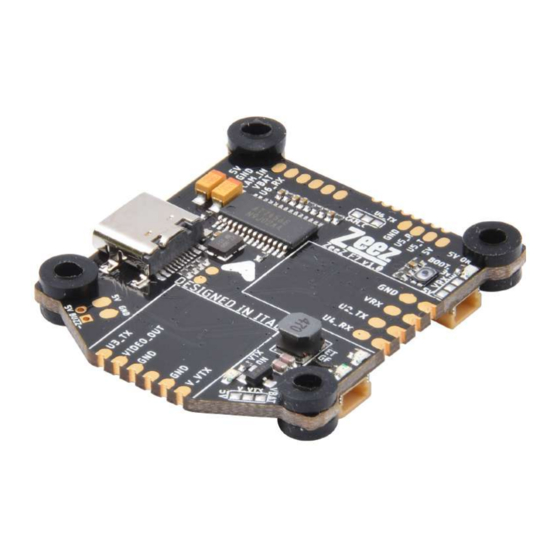
Summary of Contents for Zeez F7
- Page 1 ZEEZ F7 USER MANUAL TABLE OF CONTENTS ●Dimensions ●Introduction ●Specification ●Connection diagram ●Betaflight settings...
- Page 2 Dimensions ⑴...
- Page 3 Engineer University of Bologna that wanted to develop their own gear for racing drones. The ZeeZ F7 flight controller is our first product. In this project we thought about the most common drama that happen in FPV quad...wires break and big difficulties to stack all electronics in...
- Page 4 Connection diagram TOP connection: CAM- CONTROL (JOYSTICK EMULATION) UART6-TX ESC-TEL UART6-RX (UART1-RX) CURR VBAT+ VIDEO-IN 5V-CAM VBAT+ BOOT BUTTON 3.3V RX VOLTAGE SELECTOR UART4-RX UART4-TX UART4-RX UART2-TX BUZZER- VBAT UART3-TX VTX VOLTAGE SELECTOR VIDEO OUT TO VIDEO 5V-OUT FROM VTX ⑶...
- Page 5 BOTTOM connection: CURRENT VBAT+ SENSOR ESC-TELEMETRY (UART1-RX) LED-STRIP LED-STRIP UART4-RX UART4-TX LED-STRIP LED-STRIP VOLTAGE BUZZER- 5V-OUT FROM-VTX VIDEO UART3-TX VIDEO OUT TO VTX ⑷...
- Page 6 Betaflight settings Receiver chapter: TBS Crossfire: UART4-RX UART4-TX ⑸...
- Page 7 FrSky RXSR: Don’t forget to make the solder bridge in the left side of the Solder jumper near the RX pad to select 5V as voltage for the RX UART2-TX UART4-RX ⑹...
- Page 8 FrSky XM+: UART4-RX ⑺...
- Page 9 Spektrum DMSX FPV: Don’t forget to make the solder bridge in the right side of the Solder jumper near the RX pad to select 3.3V as voltage for the RX SELECT VOLTAGE 3.3V 3.3V UART4-RX ⑻...
- Page 10 FlySky A8S: Don’t forget to make the solder bridge in the left side of the Solder jumper near the RX pad to select 5V as voltage for the RX SELECT VOLTAGE UART4-RX ⑼...
- Page 11 VTX chapter: 5V VTX: Assign the AUX you prefer from your radio to turn ON and OFF the VTX from the transmitter from USER1 mode in BetaFlight. If USER1 is not active the VTX will remain OFF. Don’t forget to make the solder bridge in the left side of the Solder jumper near the VTX pad to select 5V as voltage for the VTX 5V-OUT VIDEO-GND...
- Page 12 HV VTX: Assign the AUX you prefer from your radio to turn ON and OFF the VTX from the transmitter from USER1 mode in BetaFlight. If USER1 is not active the VTX will remain OFF. Don’t forget to make the solder bridge in the right side of the Solder jumper near the VTX pad to select VBAT as voltage for the VTX VBAT VBAT+...
- Page 13 Camera chapter: UART control Camera: Don’t forget to make the solder bridge in the right side of the Solder jumper near the camera pad to select UART6-TX VIDEO VBAT+ UART6-RX UART6-TX UART6-TX ⑿...
- Page 14 Joystick Emulation Camera Control: For Joystick emulation everything is already set up in the firmware, you just need to wire your camera as shown below and don’t forget to make the solder bridge in the left side of the solder jumper. VIDEO CAM- CONTROL CAM- CONTROL...
- Page 15 LED Betaflight setup and connection: ⒁...

Need help?
Do you have a question about the F7 and is the answer not in the manual?
Questions and answers