Table of Contents
Advertisement
Quick Links
Advertisement
Table of Contents

Subscribe to Our Youtube Channel
Summary of Contents for Electrosmith 3340 VCO
- Page 1 Electrosmith 3340 VCO MU Build Guide...
-
Page 2: Table Of Contents
Contents Overview of the included parts ....Build ........Build . -
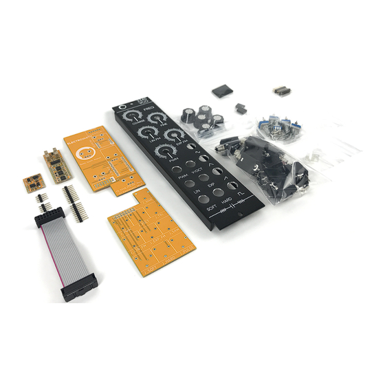
Page 3: Overview Of The Included Parts
• x10 MU Jacks • x1 Electrosmith 3340 Submodule • x1 Electrosmith 12V PSU Submodule • x1 Electrosmith 3340 VCO 1MU Top PCB • x1 Electrosmith 3340 VCO 1MU Bottom PCB • x1 Electrosmith 3340 VCO Front Panel • x2 2x8 Male Headers •... -
Page 4: Build
Build... -
Page 5: Build
Build... -
Page 6: Power Header
1. Power Header... - Page 7 The short pins should be pointing through to the top-side of the PCB, while the plastic and longer side of the pins should be visible on the back of the PCB. Make sure the plastic lock tab is facing down. The side of the PCB with the text “5U POWER”...
- Page 9 Once soldered, clip the pin labeled “K” from the power header.
-
Page 10: Link Headers
2. Link Headers... - Page 11 Populate both PCBs with the 2x8 male headers. The short pins should be pointing through to the top-side of the PCB, while the plastic and longer side of the pins should be visible on the back of the PCB.
- Page 13 All of the connections that need to be soldered are highlighted with white circles to visually assist in the build process...
-
Page 15: Submodule
3. Submodule... - Page 16 Connect the female and male headers together.
- Page 17 With the board face down, insert the female headers into the 1MU PCB.
- Page 18 Place the Electrosmith 3340 submodule and 12V PSU submodule with pin 1 (indicated by a square pad) aligned with the marker on the 1MU PCB. The trim pots, and logos should be pointing up. Solder the submodules onto the headers.
- Page 19 Flip the module over, leaning the now connected submodule against a surface that will keep all of the headers flush with the 1MU PCB. Solder the female headers into the 1MU PCB.
-
Page 21: Jacks And Pots
4. Jacks and Pots... - Page 22 Populate the PCB with the 5 10k Potentiometers. They should be seated onto the top side of the PCB (easily verified by the boxes indicating the "M-10K-B pots).
- Page 23 Populate the additional PCB with the 10 MU Jacks. They should be seated onto the top side of the PCB (easily verified by box shapes around where the jacks will be placed).
- Page 24 Install the front panel so that all of the jacks and pots fit into their holes.
- Page 25 Flip the module over, and place the front panel on two objects of equal height to ensure that gravity is holding the PCB against the jacks.
- Page 26 On the bottom side of the PCB all of the connections that need to be soldered are highlighted with white circles to visually assist in the build process. In total there will be 55 solder joints to hit on the bottom side of the PCB.
-
Page 27: Finish
Finish Affix the front panel to the jacks and pots using the included hex nuts. Once you’ve tightened them you can attach the knobs to the potentiometers by matching the cutout on the bottom of the knob with the position of the pot shaft, and pressing down. - Page 29 Attach the link cable aligning the red stripe to the white indicator on both pcb’s You’re done! Enjoy!
-
Page 30: Test
Double check that Pin 1 (GND) of the Submodule, indicated by a square copper pad, matches the pin 1 indicator on the 1 MU PCB. Attach the power cable to the Electrosmith 3340 VCO. Power on the module. A tone should emit from the top four jacks (Sine, Triangle, Ramp, Square) Adjusting the top two pots (Coarse, and Fine) should change the frequency of the tone. -
Page 31: Calibrate
Calibrate To calibrate the Frequency CV input for 1V/Octave or other musical interval tracking, you will need: • a well calibrated voltage source (musical sequencer or quantizer), or a variable DC voltage supply. • a frequency counter, musical tuner or golden ears •... -
Page 32: Symmetry Trim
6. Retune the fundamental you started with. 7. Repeat 3-6 until that octave is calibrated 8. Repeat 3-7 for each successive Voltage/octave, and/or until satisfied. Symmetry Trim This adjusts the dc offset applied to the sine waveshaper. Rotating the trimmer will push the waveform more toward the positive or negative rail.
Need help?
Do you have a question about the 3340 VCO and is the answer not in the manual?
Questions and answers