
Summary of Contents for poolstar POOLEX CHLOE
- Page 1 CHLOE Salt chlorinator OWNER’S MANUAL GARANTIE Cleaning cell by 3 years warranty Economic and ecological Long life Revers polarity...
-
Page 2: Table Of Contents
TABLE OF CONTENTS 1 . Safety Instructions ....................3 2. Pump Overview ......................4 3. Water chemistry......................5 3.1 Ideal chemical level...................5 4. Installation .......................6 4.1 Installing the control Module ................7 4.2 Adding salt .......................10 4.3 Salt levels ......................10 5. Installation checklist ....................12 5.1 How it works ....................12 5.2 Initial Start up....................12 5.3 Operation.......................13... -
Page 3: Safety Instructions
1. SAFETY INSTRUCTIONS Important notice When using electrical equipment, basic safety precautions should always be exercised, including the following: To reduce the risk of injury, do not permit children to operate this device.” WARNING - heavy pool (or spa) usage, and higher temperatures may require higher WARNING - chlorine output to maintain proper free available chlorine residuals.”... -
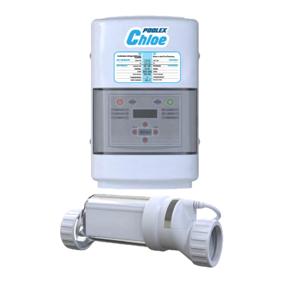
Page 4: Pump Overview
2. SYSTEM OVERVIEW List of equipements supplied • 1 complete electrolysis cell • 1 electric control unit • 1 cell power supply cable • 2 short 63/50 reducers • 1 paddle-operated flow switch • 1 wall mounting kit • 1 installation and user’s manual The chlorinator’s cell must be installed on the return circuit downstream from the filter and any heating systems (particularly electric heater) -
Page 5: Water Chemistry
3. WATER CHEMISTRY As with any pool, it is important that you maintain proper water chemistry of the pool water, including pH, alkaline content, and calcium levels. The only special requirement for Salt Chlorinator CHLOE is to maintain proper levels of salt and stabilizer. It is important to maintain these levels in order to prevent corrosion or scaling and to ensure maximum enjoyment of the pool. -
Page 6: Installation
4. INSTALLATION From the supplied components, select the plumbing fittings that match the existing pool plumbing For proper plumbing, refer to the overview diagram on page 4. NOTE: The following are basic plumbing instructions for the typical installation (Configuration #1), which entail positioning the Flow Switch and Cell adjacent to each other on 2"... -
Page 7: Installing The Control Module
4. INSTALLATION After determining the section of plumbing to install the Flow Switch and Cell, measure out and mark the selected area. 1.To install the Flow Switch, cut out a section of pipe at the desired installation location. Use PVC Primer to clean and prepare the pipe ends and interior of Flow Switch. Using plumbing Solvent Cement, glue the Flow Switch to the pipe ends. - Page 8 4. INSTALLATION Wiring: Power must be shut off at the circuit breaker before performing any wiring. Be sure to follow local and NEC/CEC electrical codes. The system has been designed to easily wire into typical in- ground pool systems. To provide safe operation, the unit must be properly grounded and bonded.
- Page 9 4. INSTALLATION Wiring to Power Source: The Control Module comes with an un-terminated Power Cord (AC Input) which is typically connected to an external timer, which will turn the pump and Control Module on and off together. Have the Control Module wired to the load side of the timer by a qualified person.
-
Page 10: Adding Salt
4. INSTALLATION It is recommended to install the control unit at a height of at least 1m60 above the ground and out of the reach of children. Be careful not to obstruct the back plate. Leave a 20cm space on sides and a 50cm space above and below the unit to ensure a proper and necessary ventilation. - Page 11 4. INSTALLATION Calculating Rectangular : Length x Width x Average Depth x 7.5 Round : Diameter x Diameter x Average Depth x 5.9 Oval : Length x Width x Average Depth x 6.7 Before adding salt, check your water for any existing salt content and add according to the chart below.
-
Page 12: Installation Checklist
5. INSTALLATION CHECKLIST Cell Unions installed and glued into pipe work. • Threaded Collars on either side of the Cell are hand tight. • Flow Switch is installed and oriented properly. • Control Module is affixed to wall and wired correctly. •... -
Page 13: Operation
5. INSTALLATION CHECKLIST To find the optimum Chlorine Output setting, start at a setting of 70% and adjust as needed over the initial start up period. Measure your available chlorine in the pool after two to three days, and adjust the Chlorine Output level accordingly. If the available chlorine is too high, lower the Output level;... -
Page 14: Automatic Coverage Detector (Optional)
5. INSTALLATION CHECKLIST Control Module Control buttons: 1. Power: Use this button to manually power the system on or off. 2. Salinity: Displays the average measurement of the most recent salinity levels in the pool water. The average is constantly being updated by real-time salinity readings. TIP: When first installed, this reading may display the last salinity readings taken at the factory. - Page 15 5. INSTALLATION CHECKLIST 7. Menu: Press sequentially to cycle through the following information: • Pool Temperature (xx degrees Fahrenheit or Celsius) • Cell Voltage (in many cases 21.0 to 27.0 volts when chlorine is being generated, otherwise 16-31V) • Cell Current (in many cases 2.50 to 7.80 amps when chlorine is being generated, otherwise 0 amps during normal rest cycles.) •...
-
Page 16: Led Indicator Light
6. LED INDICATOR LIGHT Indicator light Working status Power Located on the Power Button, this LED indicates that the Control Module is receiving input power when illuminated Generate This LED is illuminated during normal operation, and indicates that the system is able to generate chlorine. When flashing, the pool water is either too hot or too cold for chlorine generation Super CL Located on the Super CL Button, this LED is illuminated when the... -
Page 17: General Maintenance
6. LED INDICATOR LIGHT General maintenance To maintain maximum performance, it is recommended that you remove and visually inspect the cell at least every 3-4 months. The will remind you to do this at the appropriate time by flashing the “Check Cell” LED. After you inspect the cell (and clean, if necessary) press and hold the System Status button (next to the display) for 5 seconds to reset the flashing “Check Cell”... -
Page 18: To Clean The Cell Of Mineral Buildup
6. LED INDICATOR LIGHT To clean the Cell of mineral buildup 1. Attach Cleaning Cap (sold separately) and orient the Cell vertically. Place on the ground and stabilize so as to remain upright and prevent spilling. 2. In a separate bucket, mix one part muriatic acid into four parts water. Pour this weak acid solution directly into Cell. -
Page 19: Voltage Coneversion
7. VOLTAGE CONVERSION Always double-check the voltage of your power source. Connection to improper voltage can: a) cause severe damage/harm, or b) cause lights and screen to power on without system function. All service should only be attempted by a person with appropriate electrical skills, with all equipment disconnected from power. -
Page 20: Helpfull Hints
8. HELPFUL HINTS Proper operation of the chlorine generator can be easily verified by checking the lights on the control panel. However, if the pool remains cloudy, or the chlorine residual tests low, then the chlorine being produced is being lost due to high chlorine demand or improper water conditions To reduce the chlorine demand, check the pH and Stabilizer (Cyanuric Acid) reading. -
Page 21: Troubleshooting
9. TROUBLESHOOTING Diagnostic Displays Sequential pushes of the small “diagnostic” button next to the LCD display will cause the Chlorinator to display the following information:(Page 16 control button) On the 8th push of the button the display will revert back to the default salt display. Also if the button is not pushed for 30 seconds, the display will revert back default salt. - Page 22 9. TROUBLESHOOTING Problem Possible Cause Corrective Action «High Check salt level in pool/spa. If salt Salt» LED level is too high, lower salt level by illuminated draining some of the pool water out of the pool and replace with fresh water. Continue until the salt concentration is at recommended levels.
-
Page 23: Warranty
9. TROUBLESHOOTING • High level of phosphates in pool water. • Some yellow algae treatments will use chlorine at a very high rate and deplete the residual free chlorine. Manually shock the pool if indicated in the directions on the algae treatment. - Page 24 CHLOE Salt chlorinator TE CH NI C AL ASS I STANC E www.poolex.fr 01-2020...
Need help?
Do you have a question about the POOLEX CHLOE and is the answer not in the manual?
Questions and answers